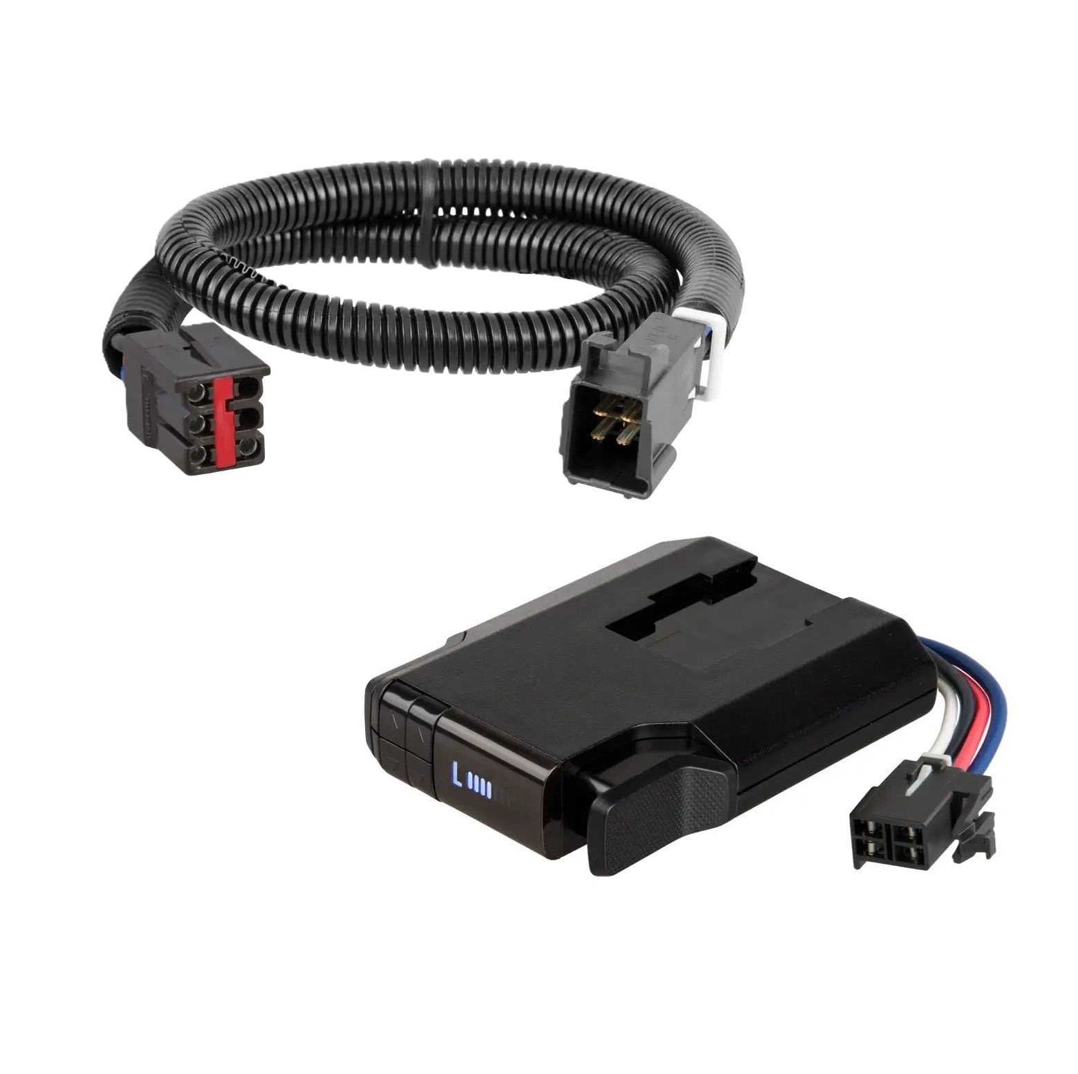
1999-2004 Ford F-250 Super Duty CURT Venturer NEXT Time-Delay Trailer Brake Controller Plug & Play Bundle - Low Profile, Adjustable, 1-3 Axles 51116CURTOriginal price was $146.90. Current price is $120.99.In Stock
View productOur in-house experts typically reply within one business day.

CURT
Verify Fitment
Select your vehicle to confirm this part fits.
1999 - 2004 Ford F-350 Super Duty
Confirmed to Fit





Always the correct part
We know our products
Quality Products
Free Shipping!
Always the correct part
We know our products
Quality Products
Free Shipping!
Finish: Blank
Installation Difficulty: Novice
Installation Time Exact (Minutes): 20
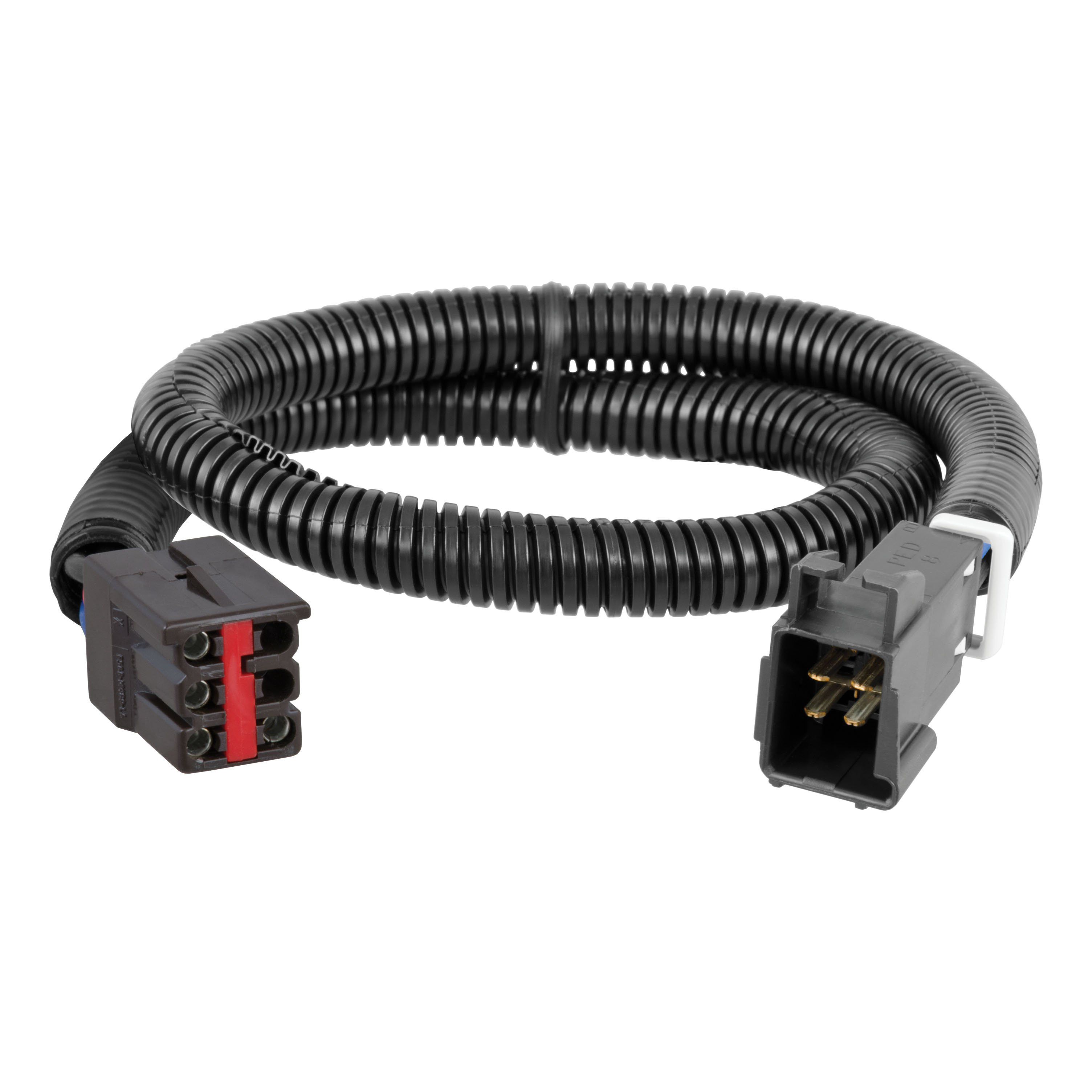
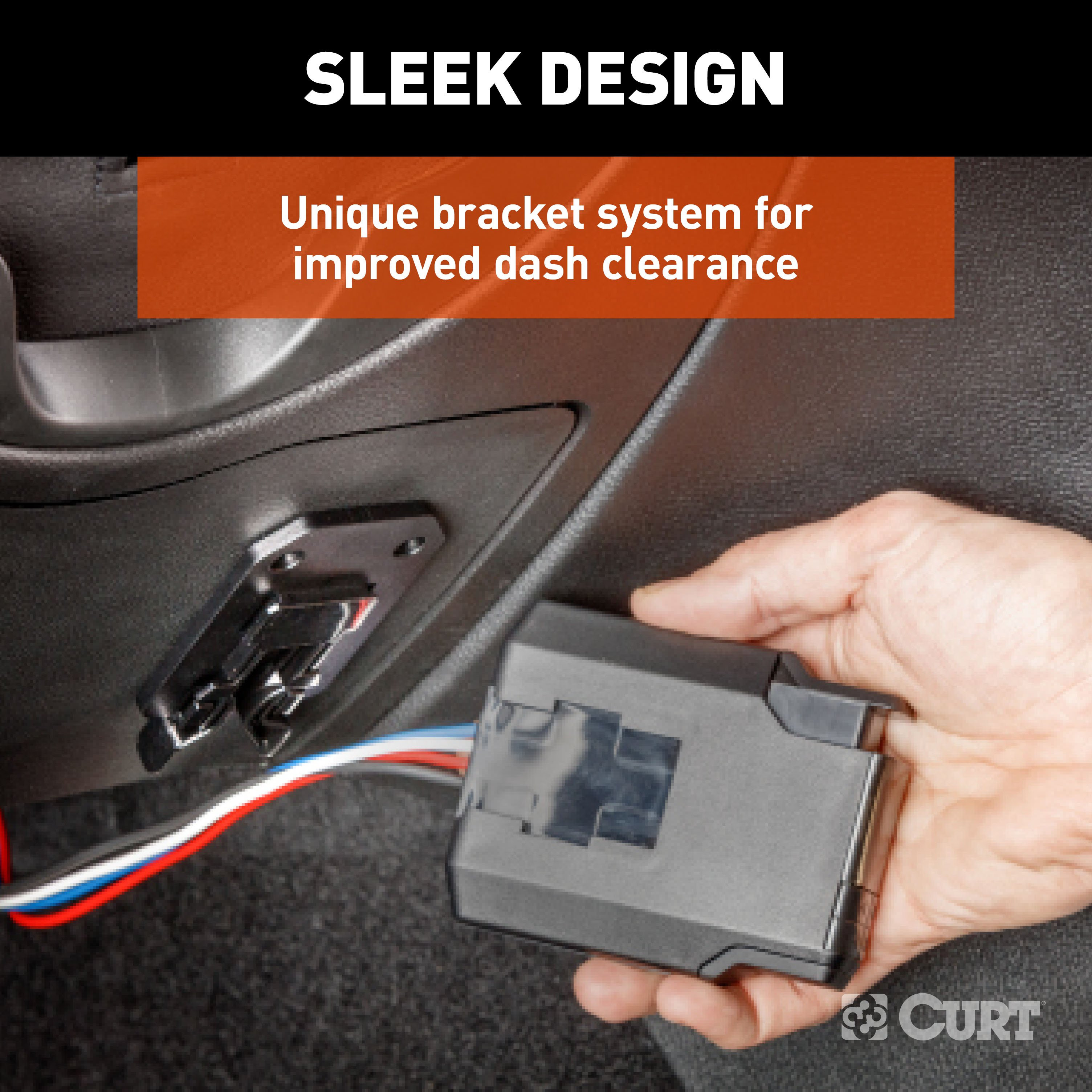
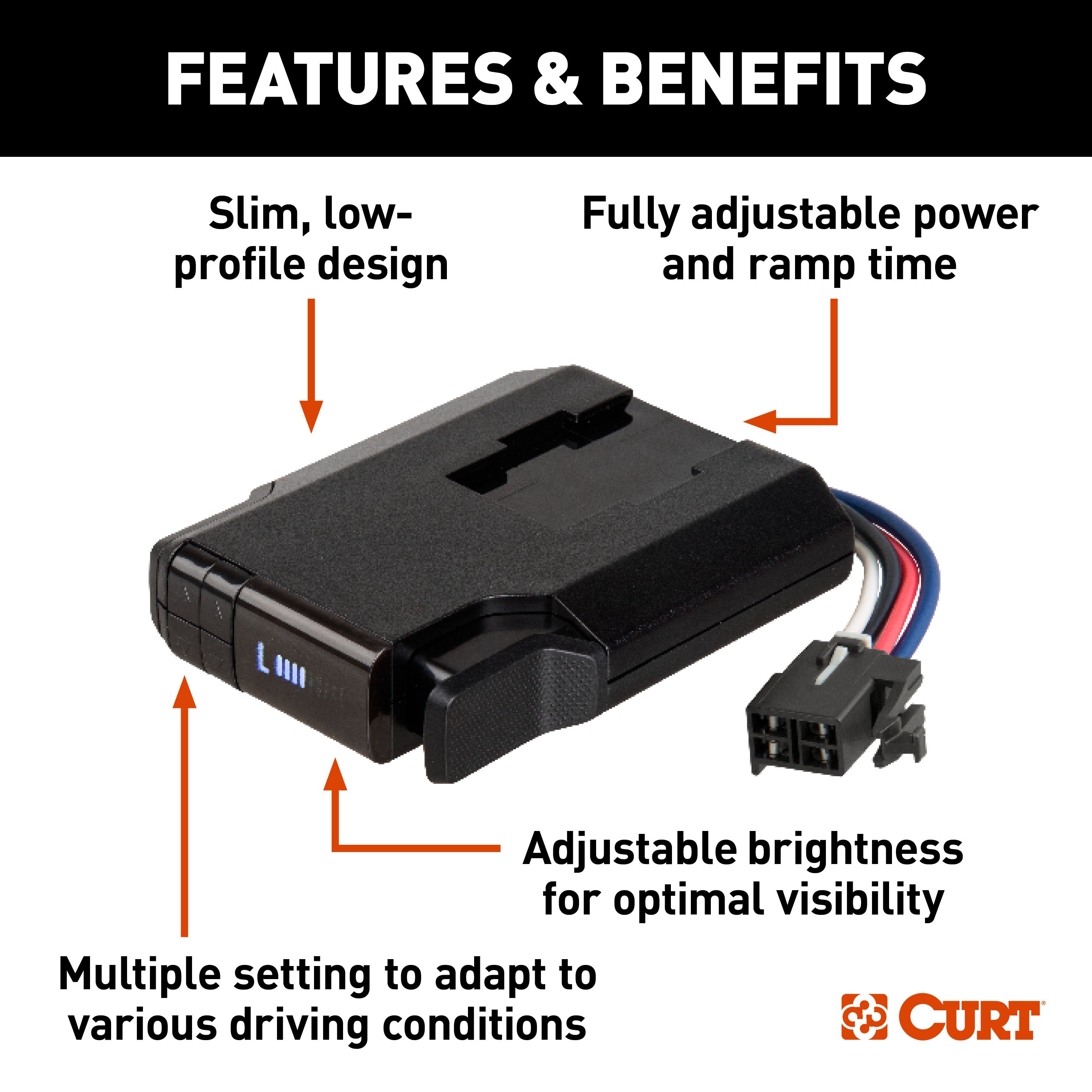
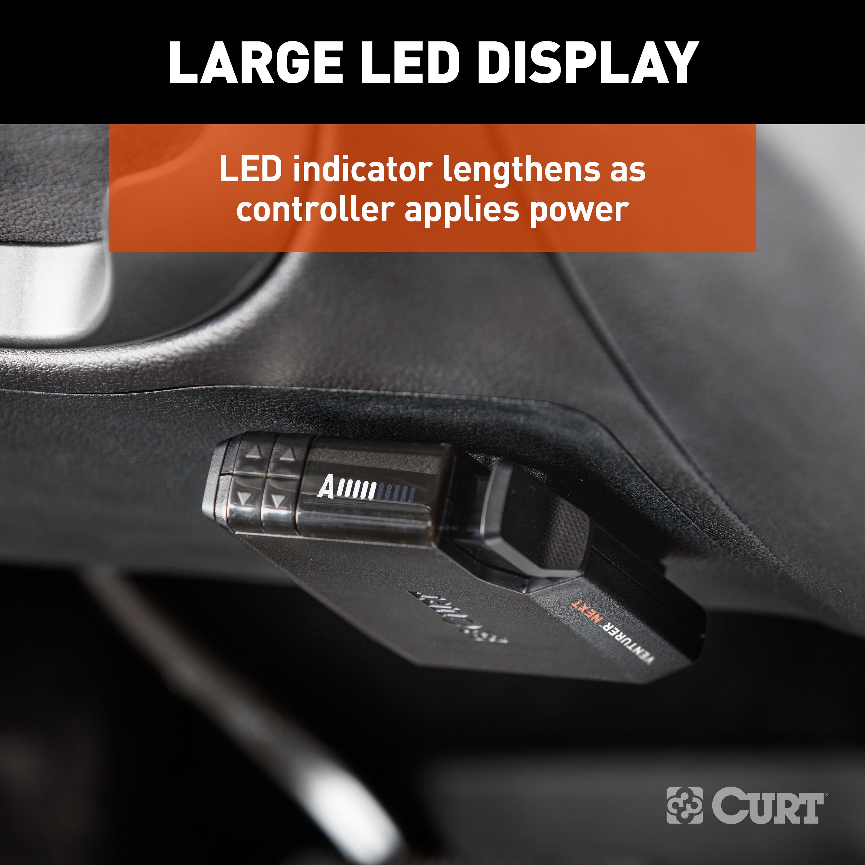
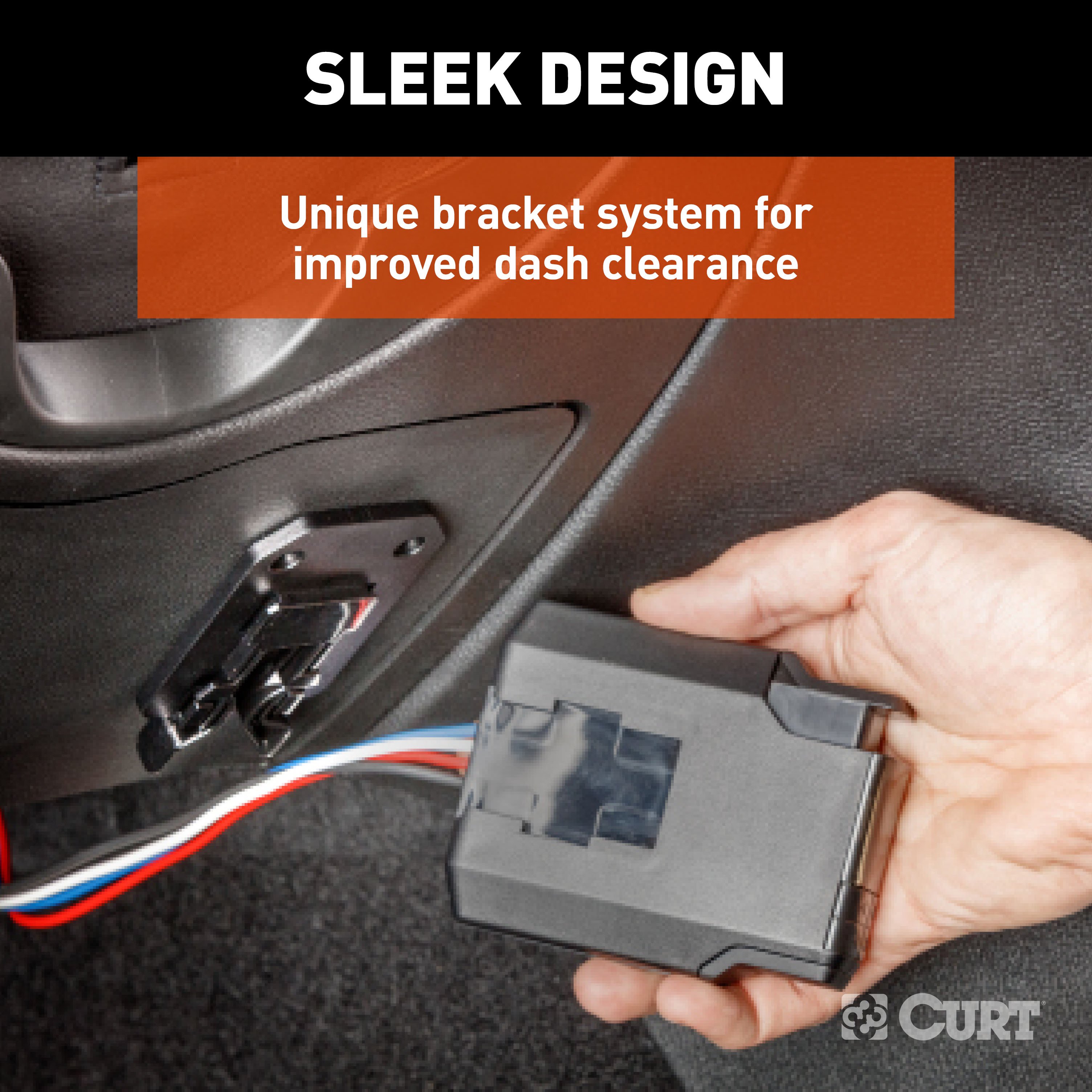
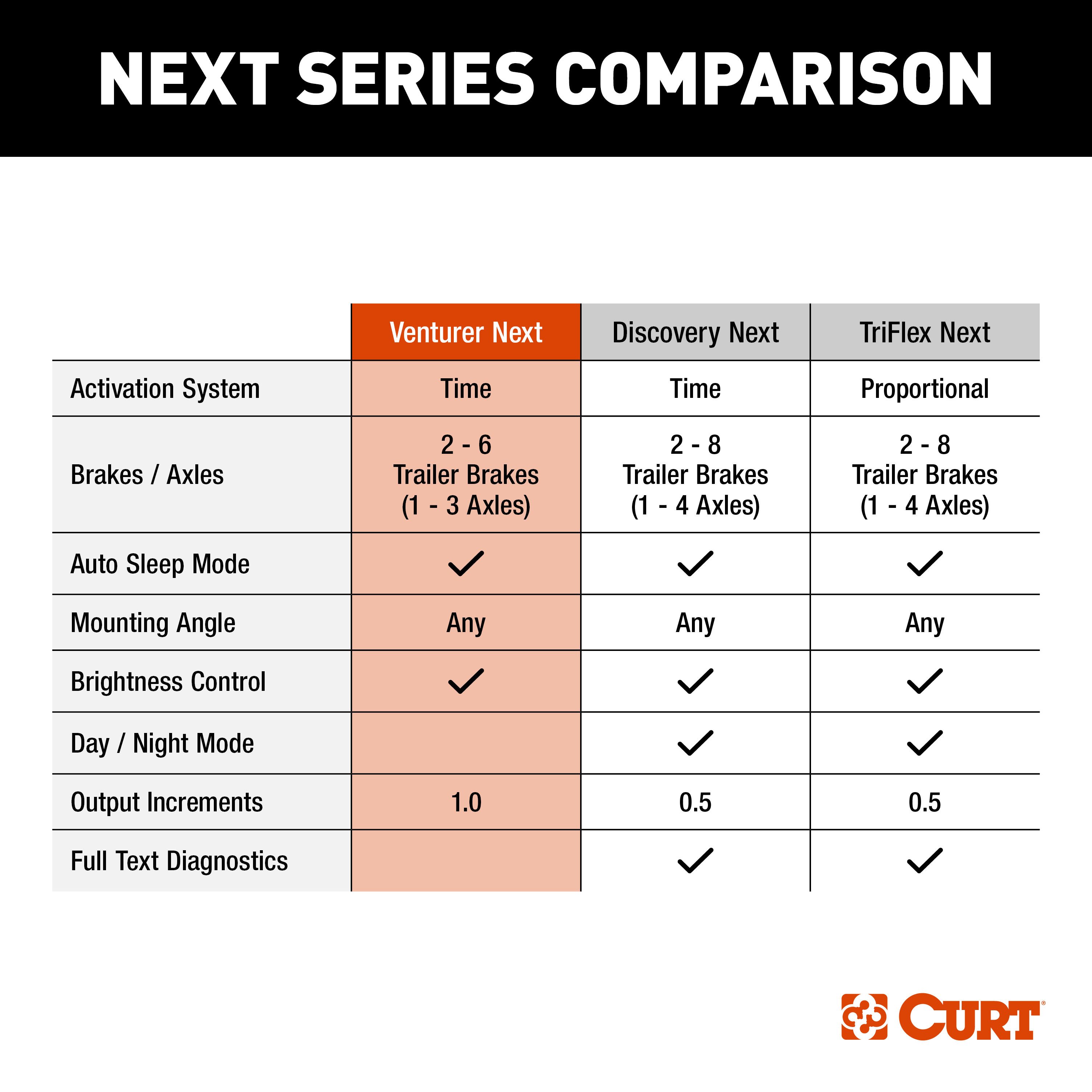
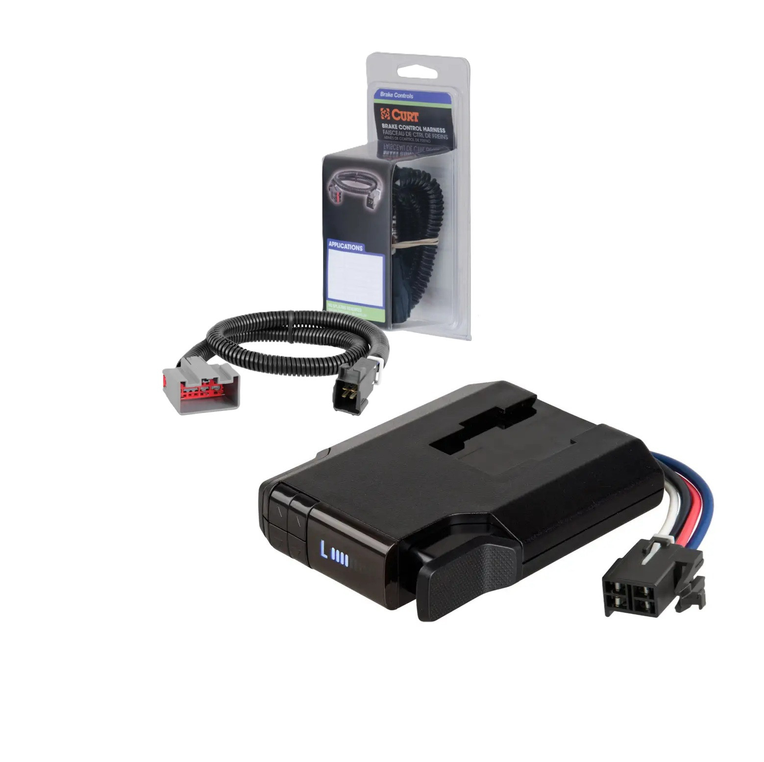
Experience the reliability and efficiency of the CURT Venturer NEXT, an intuitive and compact brake controller designed to ensure dependable operation of your electric trailer brakes directly from your vehicle's cabin. Featuring a sleek and modern design, this advanced controller is equipped with a low-profile bracket that adds clearance for enhanced functionality. With the ability to control 2-6 trailer brakes at a time (1-3 axles), it offers fully adjustable settings to perfectly adapt to your unique vehicle-trailer setup. The Venturer NEXT is a redesigned and improved version of our popular Venturer brake controller, offering compatibility with low-volt, PWM, ABS, cruise control, and electric over hydraulic brakes. Its slim profile provides a functional and contemporary aesthetic, allowing for powerful brake control at your fingertips without dominating your vehicle's dashboard. The LED display conveniently shows power adjustments in 1.0 increments, allowing you to quickly check your settings, and the brightness is adjustable for optimal visibility during day or night towing. Additionally, the included unique mounting bracket further enhances clearance, ensuring a seamless and unobtrusive installation. Equipped with a time-delay feature, the Venturer NEXT brake controller provides fully adjustable power and ramp time. Choose from a wide range of 10 gain settings and nine load settings to perfectly match your specific towing requirements. The ramp-up progress is clearly displayed through LED indicators, and the brightness can be adjusted to suit day or night-time towing conditions. This time-based brake controller is quick and easy to set up, with no internal moving parts or leveling required. It offers versatile mounting options, allowing installation at any desired location and angle within your vehicle. For convenient plug-and-play installation, it is recommended to use a CURT brake controller wiring harness (Included).

CURT offers a variety of high-quality trailer hitches and accessories for select vehicle models. Find the perfect fit for your towing needs at TowUniverse.
CURT, a Lippert brand, offers a complete line of towing products and is the leading manufacturer of custom-fit trailer hitches. We offer the broadest selection of custom-fit hitches, and each one is designed, welded, and coated in Wisconsin.
CURT is also a leader in flat towing products, as well as 5th wheel, gooseneck, and weight distribution hitches, ball mounts, electrical components, cargo solutions, and other towing accessories.
For everything from passenger cars and vans to full-size pickups and SUVs, CURT is 'The First Name in Towing Products®.'

Experts available to answer your questions
Call 888-634-9494Limited Lifetime
1 compatible vehicles
| Year | Make & Model | Notes |
|---|---|---|
| 1999 - 2004 | Ford F-350 Super Duty | — |
The 1999-2004 Ford F-350 Super Duty CURT Venturer NEXT Time-Delay Trailer Brake Controller Plug & Play Bundle - Low Profile, Adjustable, 1-3 Axles 51116 (Part #51116-51322-24) fits the following vehicles: 1999-2004 Ford F-350 Super Duty. Always verify your specific year, make, and model before ordering.
Yes, the 1999-2004 Ford F-350 Super Duty CURT Venturer NEXT Time-Delay Trailer Brake Controller Plug & Play Bundle - Low Profile, Adjustable, 1-3 Axles 51116 (Part #51116-51322-24) is designed to fit the 1999-2004 Ford F-350 Super Duty.
The 1999-2004 Ford F-350 Super Duty CURT Venturer NEXT Time-Delay Trailer Brake Controller Plug & Play Bundle - Low Profile, Adjustable, 1-3 Axles 51116 (Part #51116-51322-24) fits 1999-2004 Ford F-350 Super Duty models. The 2004 model year is the last year covered by this part number. For newer models, check for an updated version.
The 1999-2004 Ford F-350 Super Duty CURT Venturer NEXT Time-Delay Trailer Brake Controller Plug & Play Bundle - Low Profile, Adjustable, 1-3 Axles 51116 (Part #51116-51322-24) Refer to the included instructions for installation details. Basic hand tools are typically all you need.
Yes, the 51322 custom brake control harness is compatible with Ford Econoline Vans. The brake control harness connector is located under the dash to the left of the steering column (location BH1). Verify battery power is supplied to the 6-pin connector before installation.
Yes, the 51322 custom brake control harness is compatible with Ford Explorers. The brake control harness connector is located under the dash to the left of the steering column (location BH1). If equipped, you may need to remove the plastic panel under the dash by loosening the 7mm and 10mm bolts to access the connector.
The 51322 is designed for vehicles with a 6-pin vehicle brake control harness connector. Specific applications include Ford Econoline Vans and Ford Explorers. For other vehicles, the connector is typically located under the dash near the center console (location BH2). Verify your vehicle has a 6-pin brake control harness connector before purchasing.
You will need: 7mm socket, 10mm socket, ratchet, socket extension, and a panel trim removal tool. These tools are required to remove the plastic panel under the dash on some vehicles (such as Ford Explorers) to access the brake control harness connector.
The location depends on your vehicle model. For Ford Econoline Vans and Ford Explorers, the 6-pin connector is located under the dash to the left of the steering column (location BH1). For all other vehicles, it is typically located under the dash near the center console (location BH2). The connector will be similar in appearance to the brake control harness connector you are installing.
Only if your vehicle is a Ford Explorer equipped with a plastic panel under the dash. If present, loosen the 7mm and 10mm bolts securing the panel to access the brake control harness connector. For Ford Econoline Vans and other vehicles, panel removal may not be necessary depending on connector accessibility.
Use a test light to carefully probe the 6-pin connector. If the test light illuminates, power is present and you can proceed to Step 4. Alternatively, you can follow the wires to their source and check for loose connections behind the instrument panel. If no power is detected, you will need to install the universal brake control wiring kit (#51500).
You will need to install the universal brake control wiring kit (#51500). Follow the installation instructions included with that kit. To use the factory connector with the universal kit, you must cut the battery wire and trailer brake wire leading to the factory connector, leaving enough room to attach butt connectors to the wires from the universal kit. After installation, cap and/or tape the exposed ends of cut wires to prevent shorting.
Insert the connector on the custom brake control harness into the vehicle's 6-pin connector. Make sure the connector is fully inserted with locking tabs in place. Then insert the black connector of the brake control harness into the brake control's quick plug connector. Secure the harness with the provided cable ties, avoiding any pinch points.
The manual confirms that cable ties are provided with the harness to secure it in place. Use them to avoid pinch points during installation. The exact quantity and specifications are not detailed in the manual.
The manual identifies eight wiring locations (BH1–BH8) under the dash: BH1 is left of the steering column near the emergency brake pedal; BH2 is near the center console; BH3 is in the junction box left of the steering column; BH4 is behind the storage pocket above the ashtray; BH5 is behind the center access panel on the passenger side; BH6 is near the brake pedal; BH7 is behind the storage pocket in the center of the dash; and BH8 is to the right of the emergency brake pedal.
Do not exceed the product rating or the tow vehicle lamp load rating, whichever is lower. The specific product rating is not provided in the manual. Consult the brake control unit documentation or contact CURT Manufacturing for the exact capacity specification.
If you install the universal brake control wiring kit (#51500) and cut the battery or trailer brake wires, you must cap and/or tape the exposed ends of the cut wires to prevent shorting. This is a critical safety step to avoid electrical damage.
After installation, test for proper function by using a test light or by connecting a properly wired trailer. Mount the brake control unit as directed in its instructions and perform the test procedures outlined in the brake control user manual. Ensure all connectors are fully seated and locking tabs are in place.
Perform periodic inspection of all wires and connections to ensure there is no visible damage or loose connections. The manual does not specify an inspection interval, so regular checks during routine vehicle maintenance are recommended.
The 51322 is designed for vehicles with a 6-pin brake control harness connector. It is confirmed compatible with Ford Econoline Vans and Ford Explorers. For other vehicles, verify your vehicle has a 6-pin connector under the dash before purchasing.
You will need 7mm and 10mm sockets, a ratchet, socket extension, and a panel trim removal tool. These are required to access the brake control harness connector on some vehicles.
Install the universal brake control wiring kit (#51500). You will need to cut and splice the battery and trailer brake wires using butt connectors, then cap and tape the exposed ends to prevent shorting.
Do not exceed the product rating or the tow vehicle lamp load rating, whichever is lower. The specific rating is not provided in the manual; contact CURT Manufacturing for this specification.
Use a test light or connect a properly wired trailer to verify proper function. Ensure all connectors are fully seated with locking tabs in place, then follow the test procedures in the brake control unit's user manual.
No power is supplied to the brake control harness connector. You must install the universal brake control wiring kit (#51500). Follow the kit's installation instructions, cut the battery and trailer brake wires leading to the factory connector, attach them to the universal kit wires using butt connectors, and cap/tape the exposed ends to prevent shorting.
Ensure the connector is aligned correctly and being inserted straight. The manual specifies that the connector must be 'fully inserted with locking tabs in place.' If alignment is correct but insertion is still difficult, check for debris or damage to the connector pins. Do not force the connector, as this may cause damage.
Verify that: 1) the connector is fully inserted with locking tabs in place, 2) the black connector is fully inserted into the brake control's quick plug connector, 3) all cable ties are secure and not pinching wires, 4) if the universal brake control wiring kit was used, the butt connectors are secure and exposed wire ends are capped/taped. Test using a test light or properly wired trailer per the brake control unit's user manual.
The Venturer™ Next Brake Controller is an electronic brake control system that manages trailer braking when towing. It monitors the tow vehicle's brake pedal input and proportionally applies power to the trailer's electric brakes. The controller features a time-based system that ramps up to full power over time based on gain and load settings, a manual override pinch trigger for controlled braking, and an LED display showing output levels, operational modes, and diagnostic indicators.
The Venturer™ Next can be installed in most tow vehicles equipped with factory brake control plugs or in vehicles without factory plugs using CURT universal wiring kits. The manual states that most trucks and utility vehicles are equipped with a factory plug for quick brake control installation. For specific vehicle compatibility, check the CURT catalog or contact CURT product support at 877.287.8634. If your vehicle has a factory-equipped brake controller or integrated trailer brake control (ITBC), consult your vehicle owner's manual for necessary installation instructions.
If your vehicle is equipped with a factory brake controller or integrated trailer brake control (ITBC), consult your vehicle owner's manual for any necessary installation instructions before proceeding. The manual notes that removal of factory-equipped brake controls may require a dealer to service the harness in order for it to function, and splice-in harnesses may void warranty. Contact CURT product support at 877.287.8634 for guidance specific to your vehicle.
The required tools are: (1) Drill, (2) 1/8" diameter drill bit, (3) Phillips screwdriver, and (4) Pry tool. These tools are needed for drilling mounting holes, installing mounting screws, and removing anti-rattle foam from the vehicle plug.
The kit includes: (1) Main module with CURT quickplug, (2) Mounting bracket, (3) Mounting screws, (4) Base plate adhesive pad (double-sided), and (5) Cable ties for securing the wiring harness.
Depending on your vehicle, you may need one of the following: (1) Brake control harness supplied with the tow vehicle (if equipped), (2) CURT custom quick plug harness for your specific vehicle (check CURT catalog for availability), (3) CURT #51515 or #51516 quick plug with pigtails, or (4) CURT #51500 universal brake control wiring kit for vehicles not equipped with a factory brake control plug. The manual recommends the universal kit (#51500) for tow vehicles without a factory brake control plug.
Yes. The manual explicitly states: "Disconnect the tow vehicle's negative battery terminal from its battery post before beginning the installation process." This is a required safety step before any wiring work.
The 30-amp auto-reset circuit breaker protects the brake controller and vehicle electrical system. It must be mounted as close to the battery as possible. The black wire from the brake controller connects to the 'AUX' side of this breaker, which then connects to the battery. This protects against overcurrent and short-circuit conditions that could damage the brake control unit or cause vehicle fire.
The positive (with 30-amp circuit breaker) and ground wires must be connected directly to the tow vehicle's battery using a minimum of 10-gauge stranded wire. The manual emphasizes that connecting to existing wiring or an alternate ground may damage the vehicle's circuits, lead to failure of the brake control module, loss of trailer brakes, or vehicle fire. This is a critical safety requirement.
The brake controller uses the following wire colors: (1) Black wire – battery positive connection (connects to 30-amp circuit breaker 'AUX' side), (2) White wire – ground connection to battery negative, (3) Blue wire – brake output signal to trailer brakes (connects from tow vehicle's trailer plug 'BRAKE' terminal), and (4) Red wire – brake signal input from vehicle brake pedal (connects to stoplight switch). All connections use 10-gauge or 10/12-gauge butt connectors as specified in the wiring section.
After connecting the CURT custom wiring harness to the vehicle plug, route the harness into the dash area, making sure it is out of the way of any moving parts. Secure the harness with the provided cable ties. Check that your foot controls are not obstructed by the harness. When passing wires through sheet metal, always use an existing grommet. If no grommet exists, install one or use silicone sealant to protect the wires from sharp edges.
Mount the unit securely to a solid surface where it is easily accessible to the driver. The area behind the mounting location must be clear to prevent damage to the vehicle if using screws. The angle at which it is mounted will not affect the operation or calibration of the controller. The controller should be mounted where the driver can easily reach the manual override pinch trigger and view the LED display.
1. Hold the mounting bracket in your selected position and mark the hole locations on the mounting surface. Verify that mounting screws will not interfere with anything on the back side of the dash. 2. Peel off one release liner of the double-sided adhesive pad and stick it onto the brake controller mount. 3. (Optional) Using a 1/8" diameter drill bit, drill holes through the adhesive pad to see the marked locations on the dash. 4. Remove the second release liner, hold the mount slightly back from the mounting surface, then firmly press it to the dash. 5. (Optional) With a Phillips head screwdriver, start installing screws to verify hole location, then tighten to secure the bracket without over-tightening (which can strip holes). 6. Slide the controller onto the mount until it locks into place; you will hear a clicking noise when correctly installed.
Drilling is optional. The controller can be mounted using only the double-sided adhesive pad without screws. If you choose to use screws for additional security, you will drill 1/8" diameter holes through the adhesive pad to mark the mounting surface locations. The manual states this is optional and provides an alternative adhesive-only mounting method.
A 1/8" diameter drill bit is required. This is used to drill holes through the double-sided adhesive pad so you can see the marked mounting locations on the dash. This step is optional and only needed if you choose to use screws in addition to the adhesive pad.
Key safety precautions include: (1) Disconnect the tow vehicle's negative battery terminal before beginning installation. (2) Do not test a breakaway switch with the electrical plug connected between trailer and tow vehicle, as this may damage the brake control unit. (3) Do not mount the brake control module near a CB radio or other RF transmitter. (4) Connect positive and ground wires directly to the battery using minimum 10-gauge stranded wire; connecting to existing wiring may cause vehicle fire. (5) When passing wires through sheet metal, use an existing grommet or install one; use silicone sealant to protect wires from sharp edges. (6) Do not allow brake control wires, quick plug wires, push pins and test leads to contact each other or metal surfaces during bench testing, as this may damage the controller. (7) Do not over-tighten mounting screws to avoid stripping holes.
After mounting, verify that: (1) The controller is securely mounted and locked onto the bracket (you should hear a clicking noise). (2) The wiring harness is routed away from moving parts and secured with cable ties. (3) Your foot controls are not obstructed by the harness. (4) The area behind the mounting location is clear. (5) All electrical connections are complete before plugging the trailer connector into the tow vehicle plug. (6) The display powers on when the brake pedal or manual control is used.
The brake controller will sense the trailer upon connecting to the trailer plug after 10-15 seconds. However, upon connecting to the trailer and applying the brakes, the brake controller will sense the trailer immediately. Every time the vehicle starts, power is applied to the brake controller and it will restart, displaying the start up icon on the display.
The 'Connected' indicator on the LED display shows that the brake controller has recognized a trailer connection. This occurs when the controller detects the trailer brake circuit is properly connected and operational.
The 'Not Connected' indicator means the brake controller is not detecting a trailer connection. This can occur if: (1) The trailer electrical connector is not properly plugged into the tow vehicle plug, (2) The red wire is connected to the wrong side of the stoplight switch or to an incorrect wire, or (3) There is a wiring issue. Check and repair the electrical connections according to the Wiring section of the manual.
The 'Disconnected' indicator (flashing) shows that the trailer has been disconnected from the tow vehicle. If the brakes are pressed with no trailer connected, the icon will remain on as long as the brake pedal is pushed. This is a normal indicator that alerts you to the trailer's connection status.
The 'Reconnect' indicator means the trailer needs to be disconnected and reconnected to function correctly. This typically occurs when the controller has detected an issue with the trailer connection that requires a reset. Disconnect the trailer electrical connector from the tow vehicle plug and reconnect it to restore normal operation.
Gain and load adjustments should only be made while stopped, with the transmission in park or neutral, parking brake applied, foot off the brake pedal, and no manual override actuation. Gain is adjusted using the left rocker switch (upper to increase power, lower to decrease). Load is adjusted using the right rocker switch (upper to increase aggressiveness, lower to decrease). Both settings should be adjusted during initial setup and whenever trailer load changes or road conditions change. Gain and load settings will be visible for 5 seconds after adjustments are made, then the display goes into sleep mode.
To adjust brightness: (1) Long press the upper gain rocker switch (#3) on the left of the controller. (2) Use the load adjustment rocker switch (#2) to increase or decrease the brightness. The display will show the brightness level while adjusting.
To recalibrate the brake controller, restart the vehicle or disconnect the controller from the vehicle. The brake controller will retain the last settings applied upon restarting. Recalibration may be necessary if you need to reset the controller's detection of the trailer or if you are making significant adjustments to gain and load settings.
If you change your trailer load, driving conditions, or weather, you should repeat the gain and load adjustment process. Both the gain and load can be adjusted to achieve smooth, firm stops. Locate a vacant street or parking area and drive forward on a dry and level paved or concrete surface at approximately 25 mph, then apply the vehicle brakes. Adjust the gain and load settings until stops are firm and smooth. This process should be repeated for any weather, weight or loading changes to the items in or on the vehicle or trailer.
If the display does not light up, the likely causes are: (1) No power to the controller, (2) No ground connection, (3) Reversed black and white wires, or (4) Circuit breaker blown. Check and repair all connections according to the Wiring section of the manual. Verify that the black wire connects to the 30-amp circuit breaker and the white wire connects to ground. If the circuit breaker has blown, it may indicate a short circuit that needs to be located and corrected.
The 'Error 3' indicator shows a low battery voltage condition. This means the brake controller is not receiving enough voltage to provide the trailer with the needed voltage at the settings the controller is at. Check the tow vehicle's battery and charging system. The battery may be discharged or the alternator may not be charging properly. Service is needed to restore proper voltage.
The 'Error 2' indicator shows a stop lamp overload or short-circuit condition. When this occurs with manual control, the red wire is likely connected to the ground side of the stoplight switch or is shorted to ground. Check the brake control wiring and verify the red wire is connected to the correct side of the stoplight switch. You may need to change the switch setting. Refer to the Manual Control section of the manual for guidance.
The 'Error 1' indicator shows a brake overload or short-circuit condition in the trailer brake circuit. This means there is a short in the blue wire output circuit or trailer plug. Locate and correct the short in the wiring or trailer plug connection. Check for damaged insulation, loose connections, or corrosion that could cause a short circuit.
If the display shows nothing when battery power has been connected for a period of time and the engine is not being cranked, the likely cause is inadequate battery or ground wiring to the brake controller. Check all brake controller wiring, particularly the black (battery positive) and white (ground) wire connections. Verify that the black wire is properly connected to the 30-amp circuit breaker and the white wire is properly grounded to the battery negative terminal.
If the display shows 'Not Connected' when a trailer is plugged in, the problem is likely that the red wire is connected to the wrong side of the stoplight switch or to an incorrect wire. The red wire must be connected to the correct side of the stoplight switch to detect brake pedal input. Check and repair the red wire connection according to the Wiring section of the manual.
If there are no trailer brakes, check the following in order: (1) Confirm the blue wire circuit connection between the brake controller and trailer brakes. (2) Confirm connector terminal positions are correct. (3) Check the trailer brake system itself. (4) If the display shows an error, there may be a short or overload in the trailer brakes—troubleshoot the trailer brake circuit according to the brake manufacturer's instructions. (5) Check for shorts in the wiring and in each electric brake; you may see or hear sparking. (6) Check the trailer connector for proper fit and blockages. (7) Stop and check the trailer connector if there is loss of trailer connection or unplugged wiring.
If the trailer brakes work but an error is displayed, the likely causes are: (1) Miswired trailer, (2) Wiring shorted, or (3) Bulb out. Check the bulbs in the trailer brake lights. Check for possible shorts in the wiring. Verify that the trailer is wired correctly and that all connections are secure.
The Venturer™ Next fits most tow vehicles with factory brake control plugs or can be installed universally with CURT wiring kits. Check the CURT catalog or contact product support at 877.287.8634 for your specific vehicle compatibility.
You need: drill, 1/8" drill bit, Phillips screwdriver, and pry tool. Mounting can be done with adhesive only (no drilling required) or with optional screws.
No, drilling is optional. The controller mounts with a double-sided adhesive pad. Drilling 1/8" holes is only needed if you choose to add screws for additional security.
Connect positive and ground wires directly to the battery using minimum 10-gauge stranded wire. Connecting to existing wiring or alternate grounds may damage vehicle circuits, cause brake control failure, loss of trailer brakes, or vehicle fire.
The controller detects a trailer within 10-15 seconds of connecting the trailer plug. If you apply the brakes while connecting, detection is immediate.
Adjust only while stopped with transmission in park/neutral and parking brake applied. Use the left rocker switch for gain (upper increases, lower decreases power). Use the right rocker switch for load (upper increases, lower decreases aggressiveness). Repeat adjustments whenever trailer load or conditions change.
On Sale Today
Original price was $146.90. Current price is $120.99.You save $25.91 (18%)
Free Shipping
Ships free on all orders
 Authorized Dealer


Quick Ship
In stock and ready to ship — order now!
FREE ShippingFREE SHIPPING
Estimated delivery Thu, Sep 24 - Sun, Sep 27
Order before 2 PM EST Monday–Friday for same-day processing
Guaranteed safe & secure checkout
No reviews have been added for this product.