
2020 - 2024 Kia Forte Sedan, excluding GT Curt 1-1/4", Class 1 Trailer Tow Hitch + 4-flat Wiring Kit 11620CURTOriginal price was $445.90. Current price is $320.98.In Stock
View productOur in-house experts typically reply within one business day.

CURT
Verify Fitment
Select your vehicle to confirm this part fits.





Always the correct part
We know our products
Quality Products
Free Shipping!
Always the correct part
We know our products
Quality Products
Free Shipping!
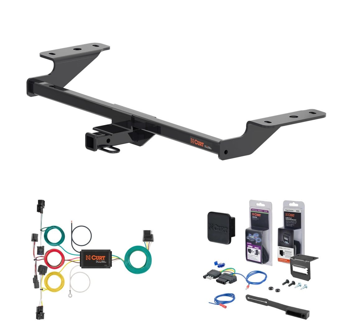
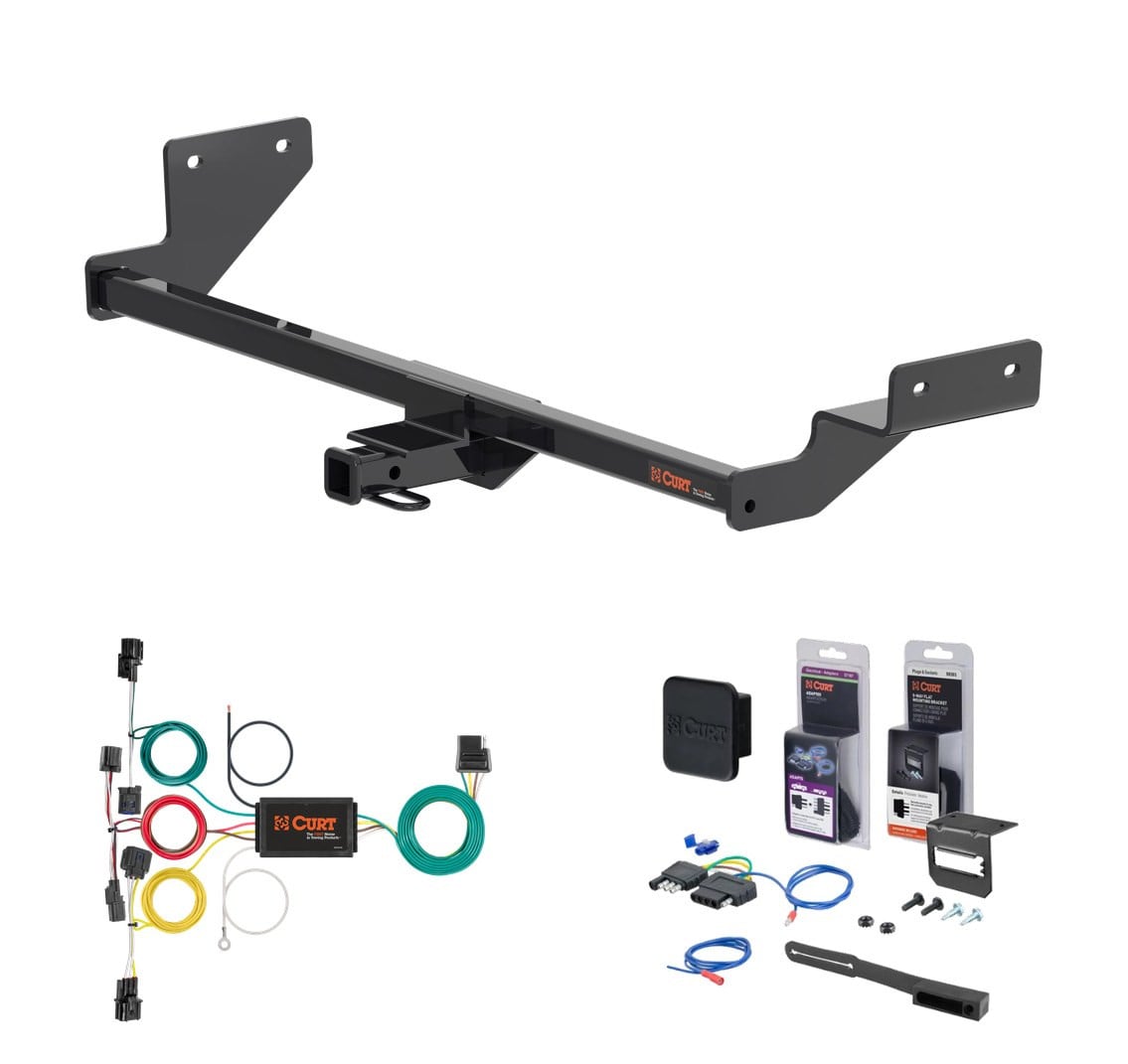
Complete CURT Class 1 1-1/4" trailer hitch and 5-flat wiring kit (with 4-way to 5-way adapter for surge brakes) engineered for the 2020 - 2024 Kia Forte Sedan, excluding GT. Vehicle-specific fit, plug-and-play installation, all hardware and instructions included.
This custom kit fits the following vehicles:
All Hardware and Installation Instructions Included!
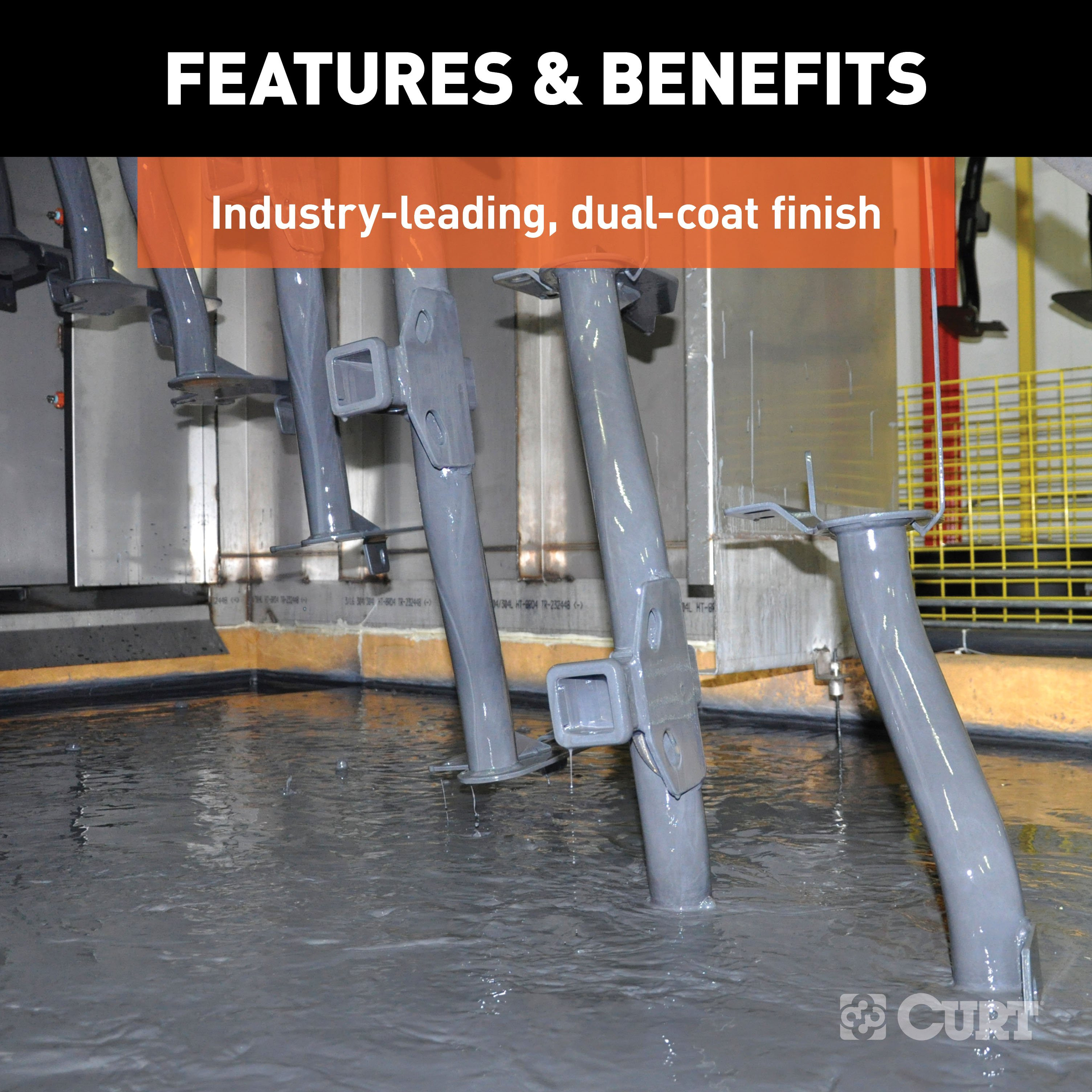
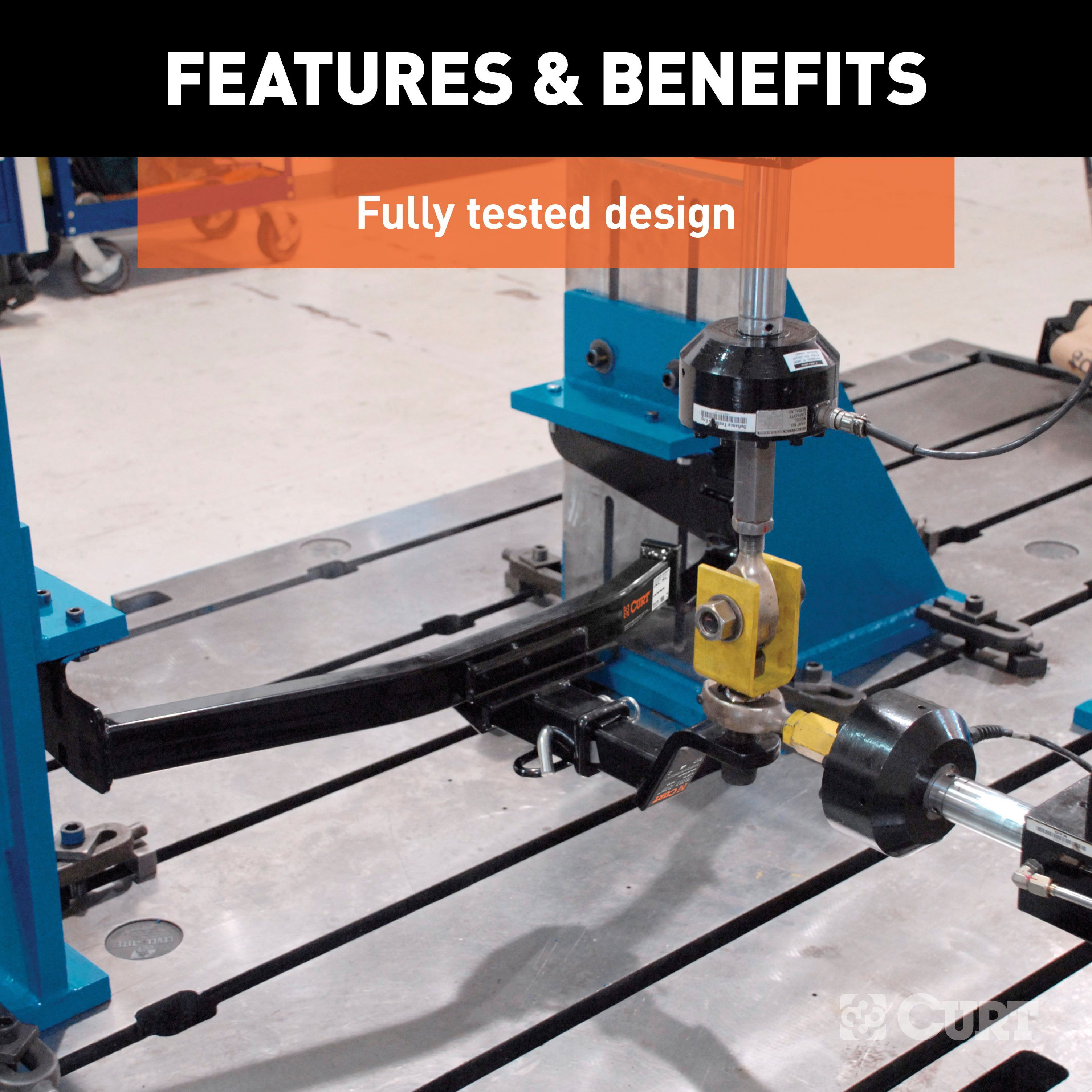
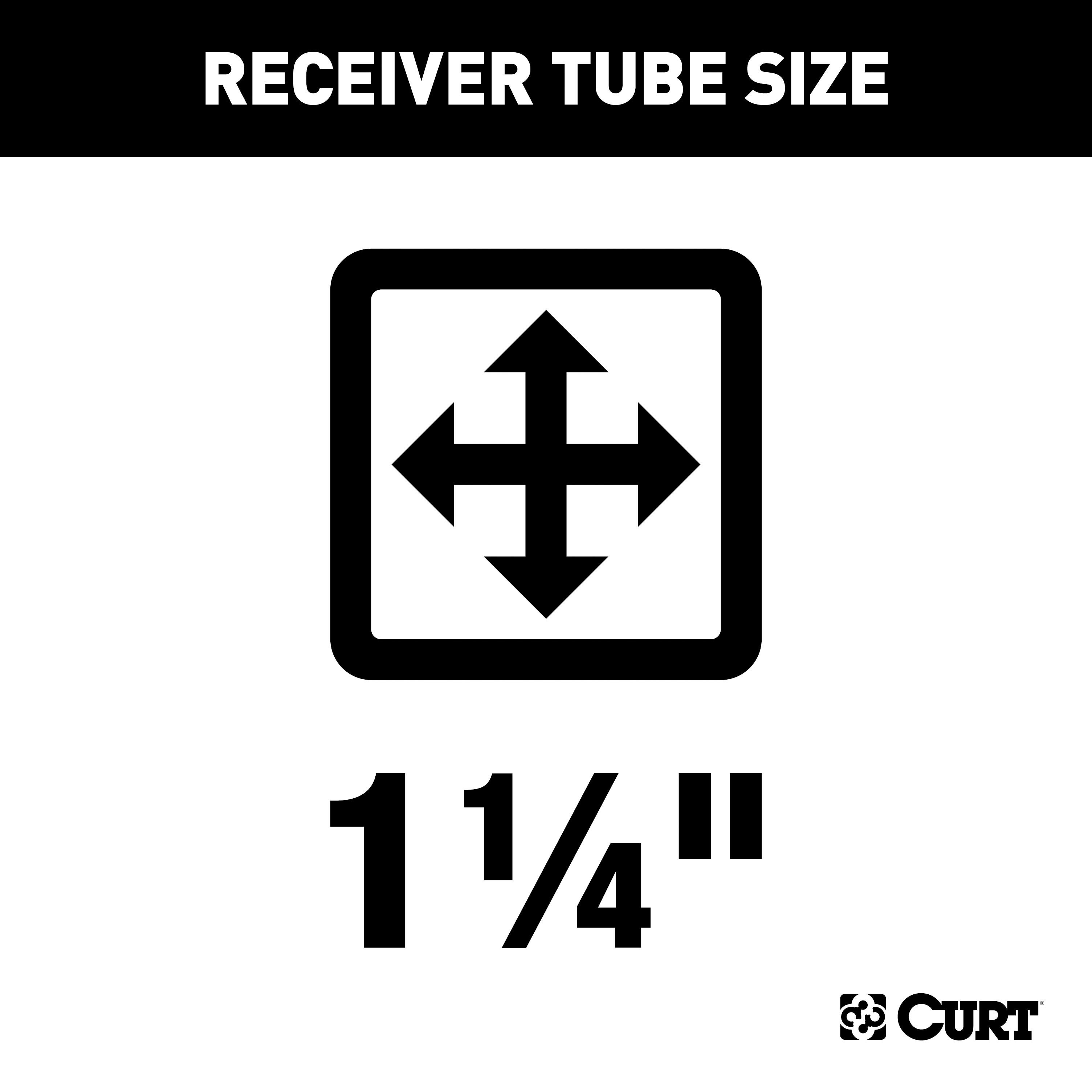
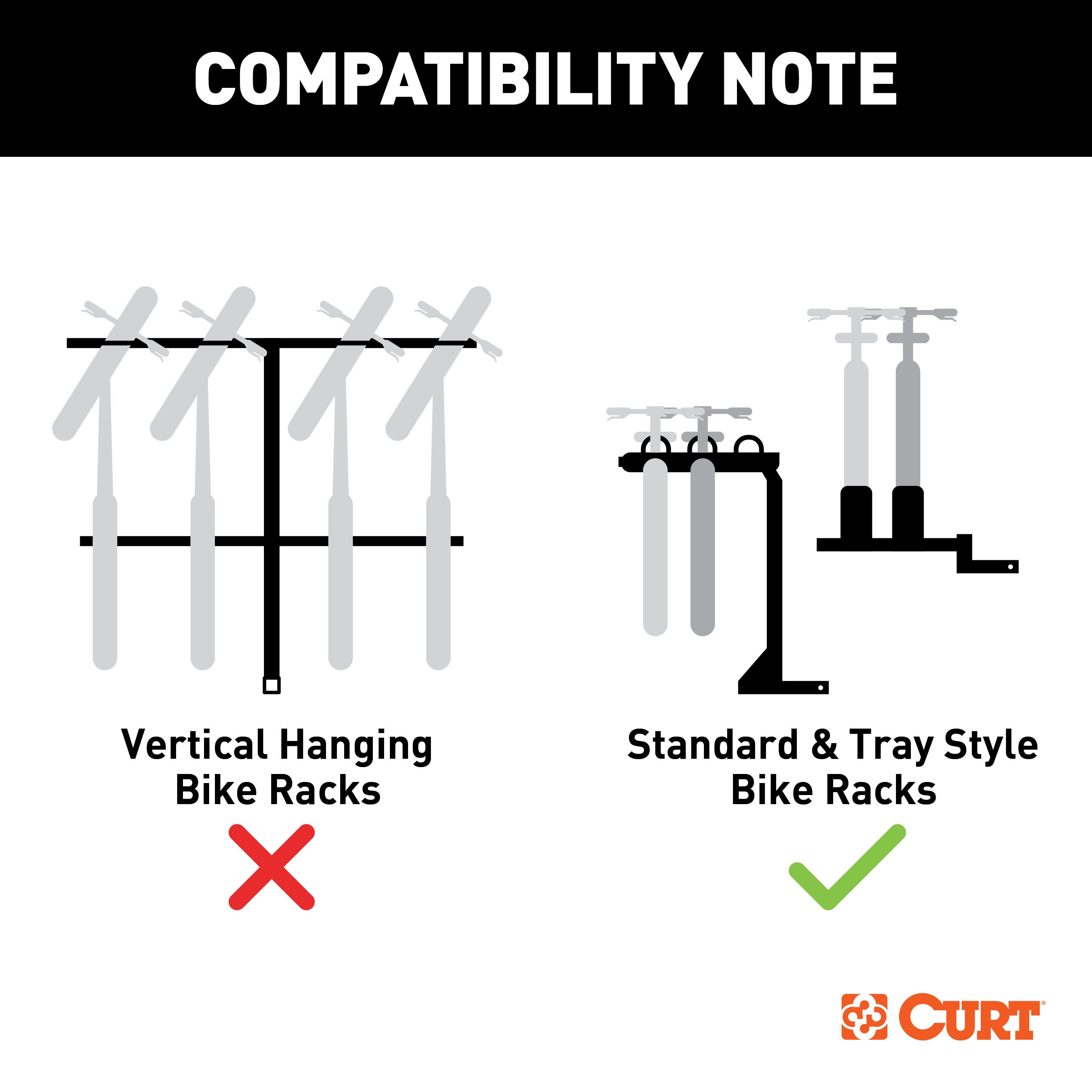
However you define adventure -- whether it's climbing onto the back of a mountain bike, hunting from the top of a tree stand or camping with the family a long way from nowhere -- CURT class 1 hitches provide a light-duty towing receiver to help you Bring It. Each is made to fit a specific vehicle, providing easier installation, a better fit and optimal towing capacity. Custom class 1 trailer hitches are available for a variety of smaller vehicle types, including the compact car, crossover, minivan and small SUV. This particular class 1 hitch is designed to be a custom hitch for certain years of the Kia Forte (to verify vehicle compatibility, see the CURT application guide at curtmfg.com). Tested in accordance with SAE J684, it offers a weight carrying capacity of 2,000 lbs. GTW and 200 lbs. TW. It is equipped with 1-1/4" receiver tube opening to accept a ball mount shank or other hitch mount. This class 1 hitch also comes with all necessary mounting hardware. With its lightweight design and smaller receiver tube size, a class 1 hitch is especially useful for adding cargo space with a hitch-mounted bike rack or cargo carrier. They can also typically be used to tow small trailers such as a utility trailer, kayak trailer or teardrop camper (never exceed the lowest weight capacity of any towing component; i.e. the vehicle, hitch, trailer, etc). Though CURT class 1 trailer hitches are only intended for light-duty towing, we apply the same principles of quality as we do to the rest of our rear mount hitches. Each class 1 hitch is made with hands-on engineering, high-strength steel and precise welding. We use a co-cured finish of liquid A-coat, inside and out, and durable black powder coat to provide a lasting defense against rust, chips and UV rays.
If your vehicle is not equipped with wiring for towing a trailer, CURT custom wiring is the ideal solution. A custom wiring harness -- also called a T-connector -- is a simple, plug-and-play electrical device that plugs into your automotive electric system and provides a standard, universal trailer wiring connection. This is done using two or more vehicle-specific, OEM-compatible connectors to plug into the taillight assembly, eliminating the need for cutting, splicing and soldering during installation. Custom wiring harnesses are made vehicle-specific, and while they are not available for all vehicles, they do offer one of the fastest, easiest and most secure ways to wire a vehicle for towing. This particular plug-in harness provides a 4-way flat connector socket and is designed to be a custom wiring harness to fit certain years of the Kia Forte (to verify your vehicle compatibility, see application info). It comes with all necessary wiring components to establish a reliable trailer wiring connection, as well as a dust cover to keep the connector clean when not in use. You have a picture in mind of your next destination -- maybe it's the boat landing at your favorite fishing spot, maybe it's a campsite that overlooks one of nature's masterpieces, or maybe it's the next big jobsite. However, turning that picture into a reality takes more than just daydreaming. It takes a solid connection and the right amount of power. CURT custom wiring is made with some of the most sophisticated technology in the industry and is designed to install with ease, giving you a long-lasting electrical connection for your towing hitch setup.

CURT offers a variety of high-quality trailer hitches and accessories for select vehicle models. Find the perfect fit for your towing needs at TowUniverse.
CURT, a Lippert brand, offers a complete line of towing products and is the leading manufacturer of custom-fit trailer hitches. We offer the broadest selection of custom-fit hitches, and each one is designed, welded, and coated in Wisconsin.
CURT is also a leader in flat towing products, as well as 5th wheel, gooseneck, and weight distribution hitches, ball mounts, electrical components, cargo solutions, and other towing accessories.
For everything from passenger cars and vans to full-size pickups and SUVs, CURT is 'The First Name in Towing Products®.'

Experts available to answer your questions
Call 888-634-94941 compatible vehicles
| Year | Make & Model | Notes |
|---|---|---|
| 2020 - 2024 | Kia Forte | Sedan, excluding GT |
On Sale Today
Original price was $472.75. Current price is $388.91.You save $83.84 (18%)
Free Shipping
Ships free on all orders
 Authorized Dealer
Yes, the 20 - 24 Kia Forte Sedan, excluding GT Curt 1-1/4" Class 1 Trailer Tow Hitch + 5-Flat Wiring Kit Tow Boat/Utility Trailer with Surge Brakes 11620 (Part #5W-CHW-2020) is designed to fit the 2020-2024 Kia Forte.
The 20 - 24 Kia Forte Sedan, excluding GT Curt 1-1/4" Class 1 Trailer Tow Hitch + 5-Flat Wiring Kit Tow Boat/Utility Trailer with Surge Brakes 11620 (Part #5W-CHW-2020) fits the following vehicles: 2020-2024 Kia Forte. Always verify your specific year, make, and model before ordering.
The 20 - 24 Kia Forte Sedan, excluding GT Curt 1-1/4" Class 1 Trailer Tow Hitch + 5-Flat Wiring Kit Tow Boat/Utility Trailer with Surge Brakes 11620 (Part #5W-CHW-2020) fits 2020-2024 Kia Forte models. The 2024 model year is the last year covered by this part number. For newer models, check for an updated version.
The 20 - 24 Kia Forte Sedan, excluding GT Curt 1-1/4" Class 1 Trailer Tow Hitch + 5-Flat Wiring Kit Tow Boat/Utility Trailer with Surge Brakes 11620 (Part #5W-CHW-2020) Refer to the included instructions for installation details. Basic hand tools are typically all you need.
The Curt 56457 is a powered converter that enables trailer lighting on passenger cars. It converts the vehicle's taillight signals (left turn, right turn, brake, and tail lights) into a 4-flat trailer connector. The converter includes a black converter box that mounts inside the trunk and a powered lead that connects to the vehicle battery for operation.
The Curt 56457 is designed for passenger cars with 12-volt negative ground electrical systems. The manual does not specify which makes, models, or years are compatible. Contact Curt Manufacturing or consult a fitment database to confirm compatibility with your specific vehicle before purchasing.
No. The converter system is designed only for 12-volt negative ground systems. It cannot be used on 24-volt systems or vehicles with positive ground electrical systems.
Required tools are: panel trim removal tool, wire crimper, flathead screwdriver, wire stripper, cutting tool, paint marker, rag/towel, and electrical tape. The manual notes that proper tools will improve installation quality and reduce time required.
The kit includes: a black converter box, a powered lead with 12-gauge wire, cable ties, double-sided tape, sealant for the grommet, a ring terminal for the ground wire, a screw for the ground connection, a 10-amp fuse holder with fuse, a 4-flat dust cover, and butt connectors. The custom wiring harness with red, brown, yellow, and green wires is also included.
Yes. Step 1 requires you to locate the vehicle's battery in the engine compartment and disconnect the negative battery terminal. Fasten this wire down and away from the battery while completing the installation. The power wire must not be connected to the battery until all other steps are complete and the system has been tested.
The manual rates the installation difficulty as Easy. However, the manual notes that installation difficulty levels are based on time and effort involved and may vary depending on the installer's level of expertise, condition of the vehicle, and availability of proper tools and equipment.
The black converter box mounts on the driver side of the trunk, on a flat spot behind the trunk liner. It is adhered using the provided double-sided tape (Step 11). The manual does not specify exact dimensions or clearances for this location.
The installation involves three separate connections: (1) Insert the custom wiring harness end with red and brown wires between the separated driver-side taillight connectors (Step 4); (2) Insert the custom wiring end with brown and red wires through the grommet opening on the driver side (Step 6); (3) Insert the yellow wire to the driver-side turn signal (Step 9); (4) Insert the green wire to the passenger-side turn signal (Step 10). For each connection, separate the connectors from the taillight housing carefully without damaging the locking tabs, insert the custom wiring end, and ensure the connectors are fully inserted with locking tabs in place.
In Step 5, run the green and yellow wires along the back of the vehicle to the center of the trunk. Remove the grommet in the lower rear of the trunk pan and route the wires through the hole. Secure the wires with zip ties as needed behind the trunk skid plate. In Step 8, locate the harness from the grommet hole in the trunk pan and route the yellow wire to the driver-side turn signal, securing loose wires with provided cable ties. Repeat this process with the green wire to the passenger-side turn signal (Step 10).
After routing the custom wiring through the grommet opening in Step 6, you must use the provided sealant to seal the cut in the grommet and around all the wires. This prevents water and debris from entering the vehicle through the grommet hole.
Route the 12-gauge black power wire from the vehicle battery to the converter, taking care to avoid pinch points and hot or rotating components. Use existing grommets or add new ones to protect the wire from sharp edges. Secure the power wire to the vehicle chassis using the provided cable ties. Use a ring terminal for the battery connection. Install the 10-amp fuse holder with fuse after all other steps are complete. Do not connect the power wire until the system has been tested with a test light, 4-flat tester, or functioning trailer.
When not in use, roll up the 4-flat connector and store it in a convenient, out-of-the-way location. Secure any loose wires with the provided cable ties. Install the provided 4-flat dust cover to help prevent corrosion.
Drilling may be required for the ground wire connection. The white ground wire ring terminal attaches to the vehicle body using a provided screw. If a suitable existing hole is not available, you must drill a 3/32-inch hole. The manual also warns to check for miscellaneous items behind or under any surface before drilling to avoid personal injury or property damage.
Yes. In Step 6, you must locate the grommet behind the taillight where the vehicle's taillight wiring passes from inside the cabin to the taillight. Remove the grommet and cut a slit large enough to route the new custom wiring end through. After routing the wires, reseat the grommet and use the provided sealant to seal the cut in the grommet and around all the wires.
Signal circuits are rated at 3.0 amps per side. Tail and running circuits are rated at 6.0 amps total. Do not exceed the product rating or the tow vehicle lamp load rating, whichever is lower. Exceeding the product rating can cause loss of warranty, overheating, and potential fire.
The battery connection must be fuse-protected with a 10-amp maximum fuse. The kit includes a fuse holder with a 10-amp fuse. Install the fuse after all other installation steps are complete. Exceeding this rating can cause loss of warranty, overheating, and potential fire.
The power lead uses 12-gauge wire or larger. This wire routes from the vehicle battery to the converter system and must be protected from sharp edges using existing grommets, new grommets, or silicone.
The white ground wire ring terminal attaches to the vehicle body using a provided screw. If a suitable existing hole is not available, drill a 3/32-inch hole.
The custom wiring harness uses the following color code: Green = Right turn signal, Red = Brake, Yellow = Left turn signal, Brown = Tail light. These wires connect to the corresponding vehicle taillight circuits and the 4-flat trailer connector.
The manual identifies seven wiring locations for passenger cars: P1 (behind driver side taillight housing, outside of trunk), P2 (behind passenger side taillight housing, outside of trunk), P3 (behind driver side taillight housing, inside of trunk), P4 (behind passenger side taillight housing, inside of trunk), P5 (behind driver side rear bumper), P6 (behind center of rear bumper), and P7 (behind passenger side rear bumper). The installation uses locations P3, P5, and P7.
The manual does not specify a tow load rating. It states only that you must not exceed the product rating or the tow vehicle lamp load rating, whichever is lower. Consult the vehicle owner's manual or contact the vehicle manufacturer for tow rating information.
Route the 12-gauge power wire to avoid pinch points and hot or rotating components. When passing the power wire through sheet metal, use an existing grommet, add a grommet, or use silicone to protect the wire from sharp edges. Secure the power wire to the vehicle chassis using the provided cable ties. Disconnect the negative battery before wiring the power wire.
After connecting the 12-volt power wire to the harness, verify that the harness is functioning by attaching the battery and testing with a test light, 4-flat tester, or a functioning trailer. Do not install the fuse until all other steps are complete and the system has been tested.
Reinstall all items removed during installation. If the negative battery terminal was disconnected at the beginning, reconnect it. Install the provided 4-flat dust cover to help prevent corrosion. Perform a functional test using a test light, 4-flat tester, or functioning trailer before towing.
Periodic inspection of all wires and connections should be performed to ensure there is no visible damage or loose connections. The manual does not specify an inspection interval. Install the provided 4-flat dust cover to help prevent corrosion when the connector is not in use.
The battery connection must use a 10-amp maximum fuse. The kit includes a 10-amp fuse holder. Install the fuse after all other steps are complete.
Green = Right turn, Red = Brake, Yellow = Left turn, Brown = Tail light. The power lead uses 12-gauge black wire to the battery and white wire for ground.
The CURT 11620 has a gross trailer weight (GTW) capacity of 2,000 lbs and a tongue weight (TW) capacity of 200 lbs.
Yes. Installation requires drilling the rearward-most mounting holes in the bottom of the frame rails (Step 8), as well as enlarging existing access and mounting holes to allow carriage bolts and spacers to pass through (Step 6).
Yes. Step 2 requires lowering the exhaust by removing three rubber exhaust isolators. The manual notes that you must support the exhaust to prevent damage during this process.
Step 1 requires removing the driver-side underbody panel by removing three push fasteners and two nuts (using a 10mm socket) and one captured nut (using an 11mm socket). The lower rear fascia must also be removed in Step 3 by removing two screws and eight push fasteners, then pushing down on retaining fasteners while pulling the panel away from the vehicle.
Yes. Step 5 requires removing the heat shield and trimming it using the provided diagram for reference. The heat shield is then reinstalled without the rearmost nut on the bottom of the frame rail.
Yes. Step 11 requires trimming the bumper fascia using the provided diagram for reference. The trimmed fascia is then reinstalled using cable ties around the hitch where fascia supports were removed.
The kit includes: 4 carriage bolts (1/2"-13 x 1-1/2", grade 8), 4 square-hole spacers (1/4" x 1" x 3"), 4 serrated-flange nuts (1/2"-13), and 2 cable ties (3/16" x 8").
Required tools are: ratchet, aviation shears, torque wrench, die grinder, 10mm socket, 11mm socket, 3/4" socket, 9/16" drill bit, drill, tape, 1/2" fishwire (4 qty included), tape measure, and flathead screwdriver. A 5/8" open-end wrench and pry bar are also needed for exhaust isolator removal if exhaust hanger removal pliers are not available.
All 1/2" hardware must be torqued to 110 ft-lbs (Step 10).
The fishwire technique (Steps 7 and 9) is used to guide carriage bolts and square-hole spacers through the enlarged mounting holes in the frame rails without losing them inside the frame. The coiled end of the fishwire is inserted through the hitch mounting hole and out the access hole, passed through the spacer, and threaded with the bolt. The wire is kinked to keep the spacer separate from the bolt, then pulled to guide the hitch into position and secure it with serrated-flange nuts.
Step 2 requires removing three rubber exhaust isolators. If exhaust hanger removal pliers are not available, use a 5/8" open-end wrench and a pry bar: slide the wrench up to the rubber isolator, cradling the hanger rod, then place the flat edge of the pry bar between the wrench and the hanger stop or rod, and rotate the pry bar toward the wrench to remove the isolator. Using lubricant or soapy water on the hanger rod and isolator helps removal. Support the exhaust to prevent damage.
1. Remove driver-side underbody panel (Step 1). 2. Lower exhaust by removing three rubber isolators (Step 2). 3. Remove lower rear fascia (Step 3). 4. Remove plastic fascia support brackets (Step 4). 5. Remove and trim heat shield (Step 5). 6. Enlarge access and mounting holes (Step 6). 7. Fishwire first set of bolts and spacers, raise hitch into position, and secure with nuts (Step 7). 8. Drill rearward-most mounting holes (Step 8). 9. Fishwire remaining bolts and spacers and secure with nuts (Step 9). 10. Torque all 1/2" hardware to 110 ft-lbs (Step 10). 11. Trim bumper fascia and reinstall with cable ties (Step 11). 12. Reinstall exhaust isolators and underbody panel (Step 12).
Step 6 requires enlarging two holes: the access hole on the inside of the frame rail must be enlarged enough to allow a carriage bolt and spacer to pass through, and the mounting hole on the bottom of the frame rail must be enlarged enough to allow carriage bolt threads to pass through. The manual specifies using a die grinder and 9/16" drill bit as required tools, but does not specify exact final hole sizes.
Step 8 requires drilling the rearward-most mounting holes in the bottom of the frame rails using the hitch as a template. The manual does not specify exact hole locations or dimensions.
Safety glasses must be worn at all times during installation. When lowering the exhaust (Step 2), support it to prevent damage. Never exceed the vehicle manufacturer's recommended towing capacity when using the hitch.
Periodic inspection of the trailer hitch should be performed to ensure all mounting hardware remains tight and structural components are secure.
Yes. Installation requires drilling the rearward-most mounting holes in the frame rails and enlarging existing access and mounting holes.
Gross trailer weight capacity is 2,000 lbs with a tongue weight capacity of 200 lbs.
You will need a ratchet, torque wrench, die grinder, drill with 9/16" bit, 10mm and 11mm sockets, 3/4" socket, aviation shears, tape, tape measure, flathead screwdriver, and 1/2" fishwire (included).
All 1/2" hardware must be torqued to 110 ft-lbs.
Yes. Three rubber exhaust isolators must be removed to lower the exhaust. Support the exhaust to prevent damage.
Yes. Both the heat shield (Step 5) and bumper fascia (Step 11) must be trimmed using the provided diagrams.


Quick Ship
In stock and ready to ship — order now!
FREE ShippingFREE SHIPPING
Estimated delivery Tue, Sep 29 - Fri, Oct 2
Order before 2 PM EST Monday–Friday for same-day processing
Guaranteed safe & secure checkout
| Bulk # | Pkg # | Width | Height | Depth | Description | Loads From | Includes |
|---|---|---|---|---|---|---|---|
| Breakaway Replacement Parts | |||||||
| 52010 | 52011 | -- | -- | -- | Breakaway switch with 10' leads | -- | Nylon case with weldable high-temp, metal tab and silver contact points |
| 52020 | 52021 | -- | -- | -- | 48" lanyard | -- | -- |
| 52023 | -- | 3-1/2" | 4" | 2-3/4" | Sealed lead acid battery for 1-3 axle trailers (12-volt, 5 amps per hour) | -- | -- |
| 52025 | -- | -- | -- | -- | 12-volt battery charger plug | -- | -- |
| Replacement Battery Cases | |||||||
| 52029 | -- | 5" | 3-1/4" | 3-7/8" | 3-1/8" inside bracket depth | Top | Weldable metal bracket for easy mounting on A-frame or jack posts |
| 52030 | -- | 5" | 3-1/4" | 3-7/8" | -- | Side | -- |
| 52027 | -- | 5" | 3-3/8" | 3-3/4" | Watertight case with rubber gaskets and screw-tight lid | Top | Four-screw lid |
| 52022 | -- | 6" | 5-1/2" | 3-1/4" | -- | Top | Lockable tab and a bolt-on mount |
| 52090 | -- | 5-7/8" | 5-3/8" | 3-1/2" | -- | Top | Metal bracket / locking bar for security |
No reviews have been added for this product.