
2003-2006 Cadillac Escalade Tekonsha Voyager Proportional Brake Controller for Trailers with 1 to 4 Axles Black 9030Tekonsha$158.69Out of Stock
View productOur in-house experts typically reply within one business day.

Tekonsha
Verify Fitment
Select your vehicle to confirm this part fits.
2003 - 2006 Cadillac Escalade ESV
Confirmed to Fit



Always the correct part
We know our products
Quality Products
Free Shipping!
Always the correct part
We know our products
Quality Products
Free Shipping!

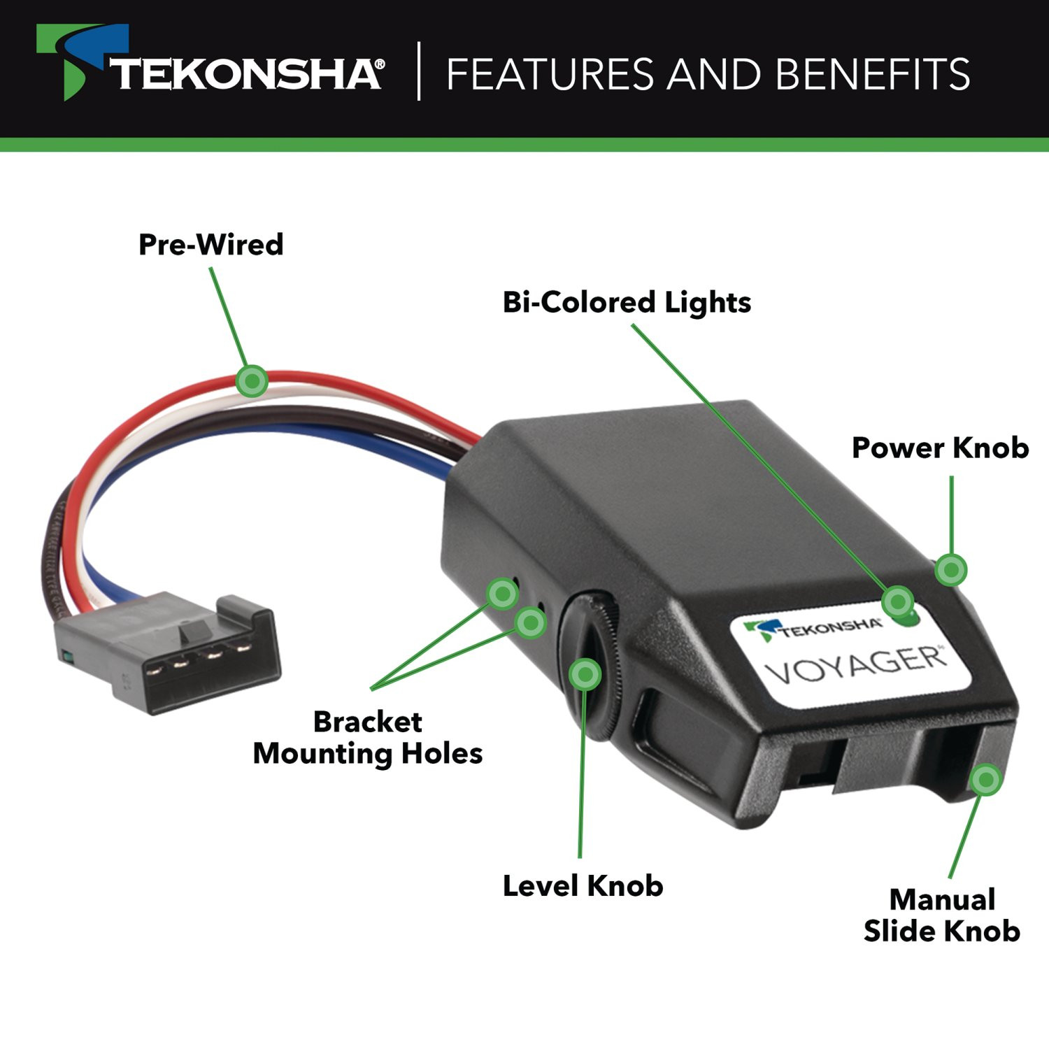
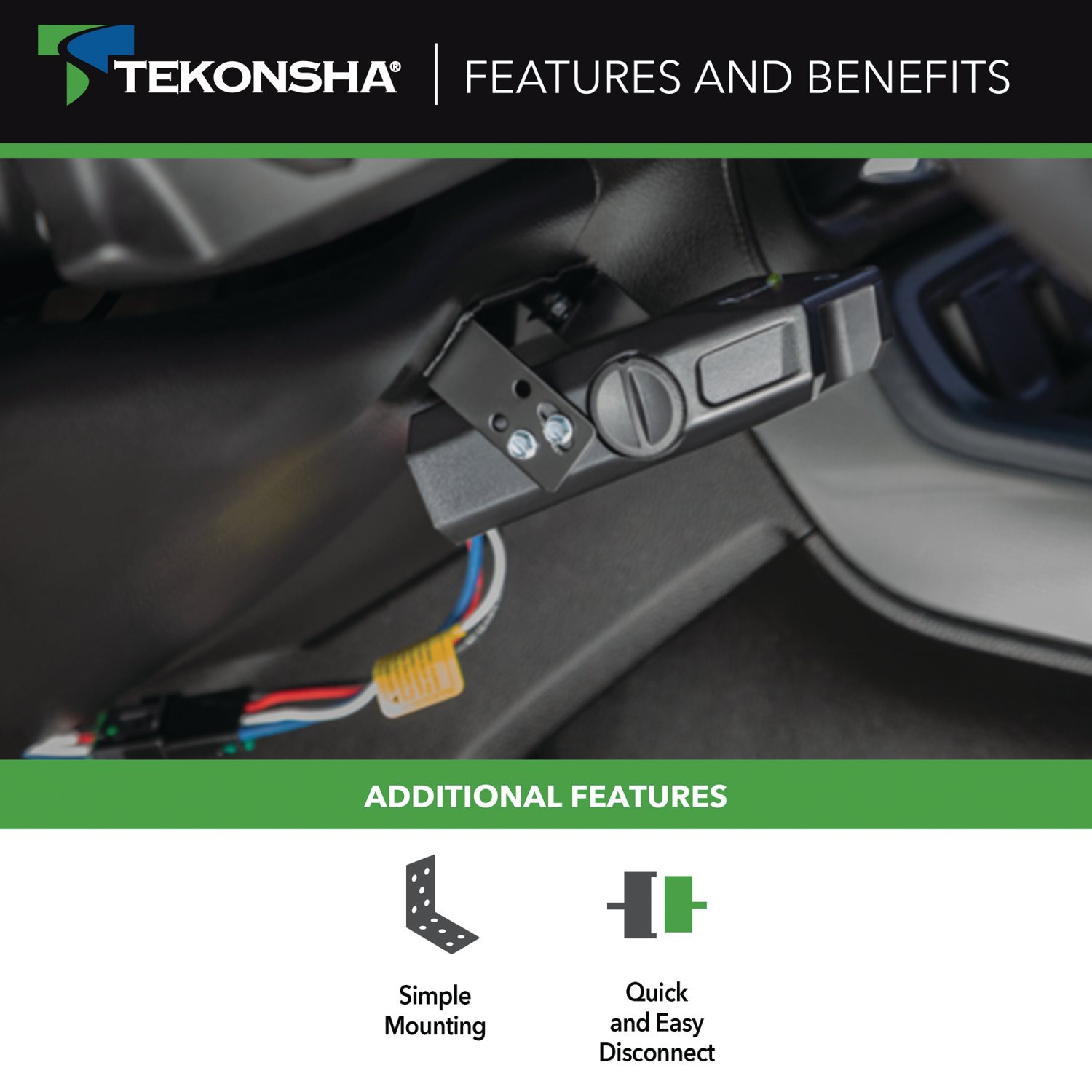
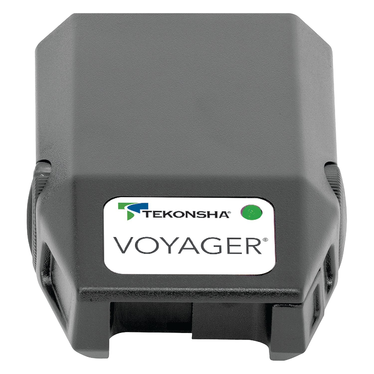
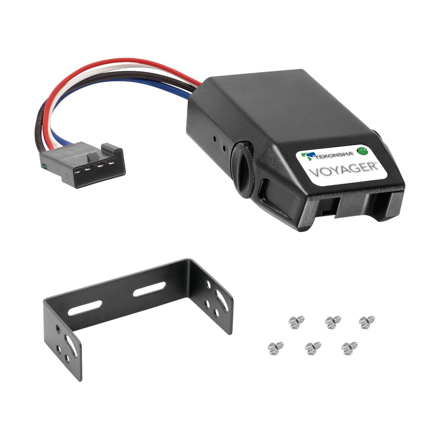
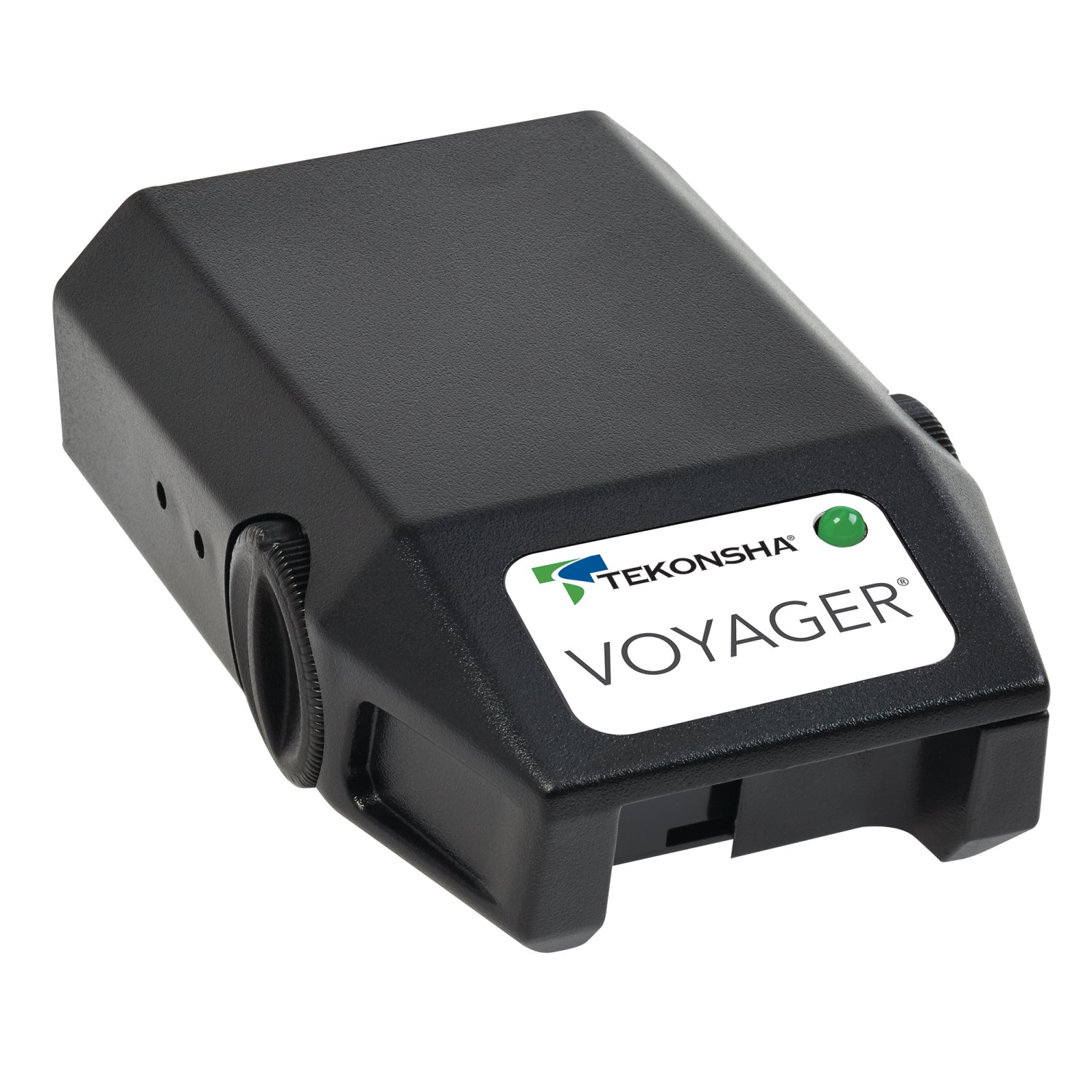
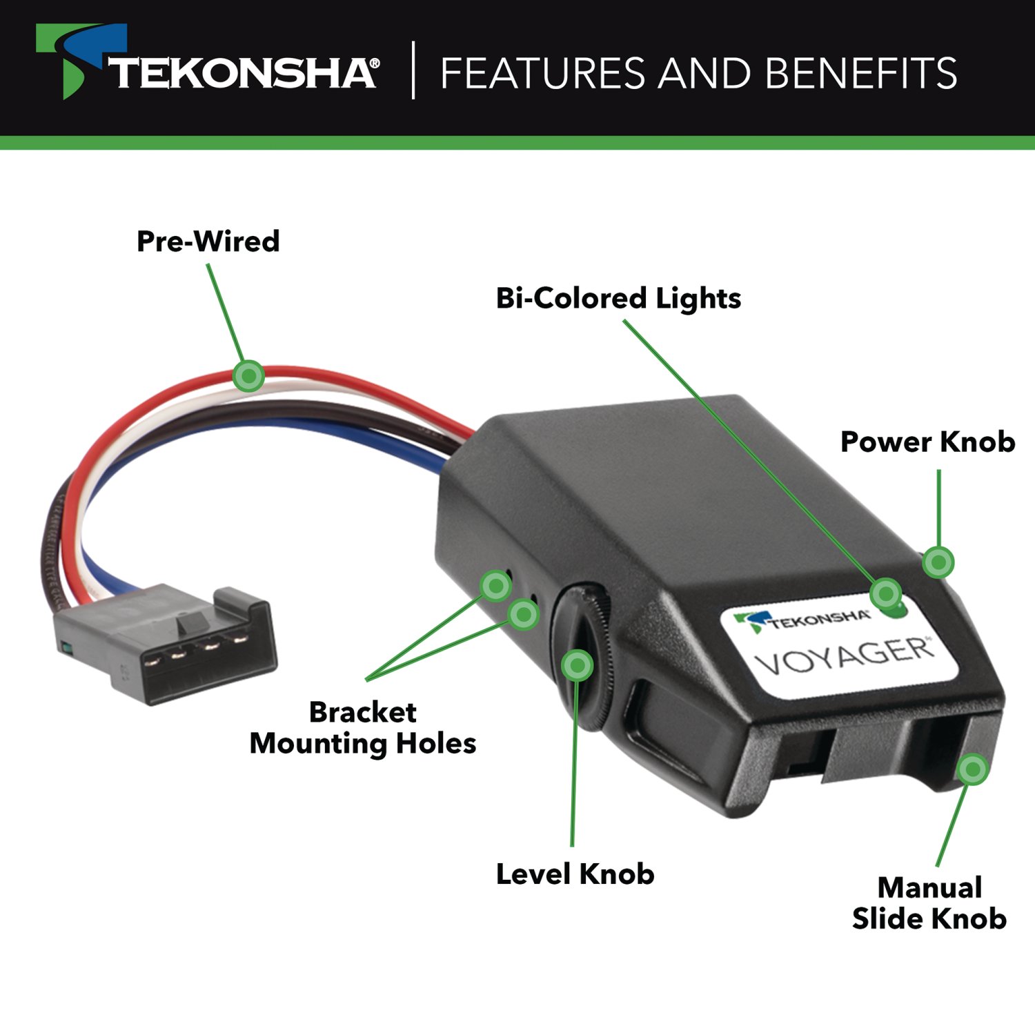
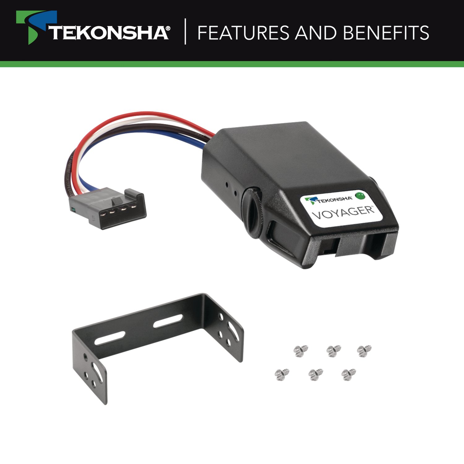
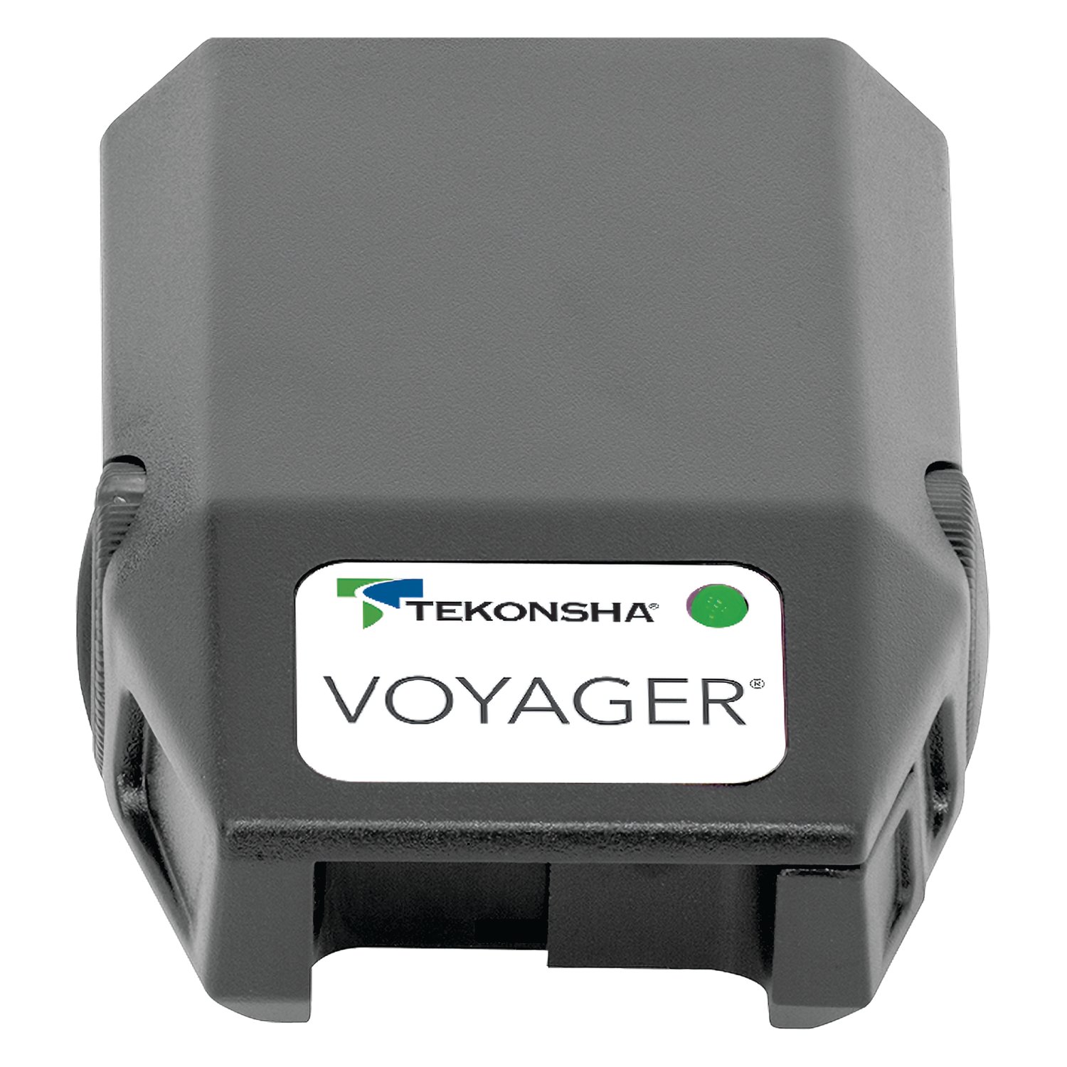
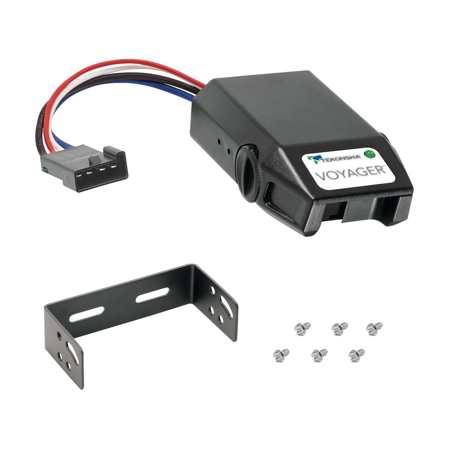
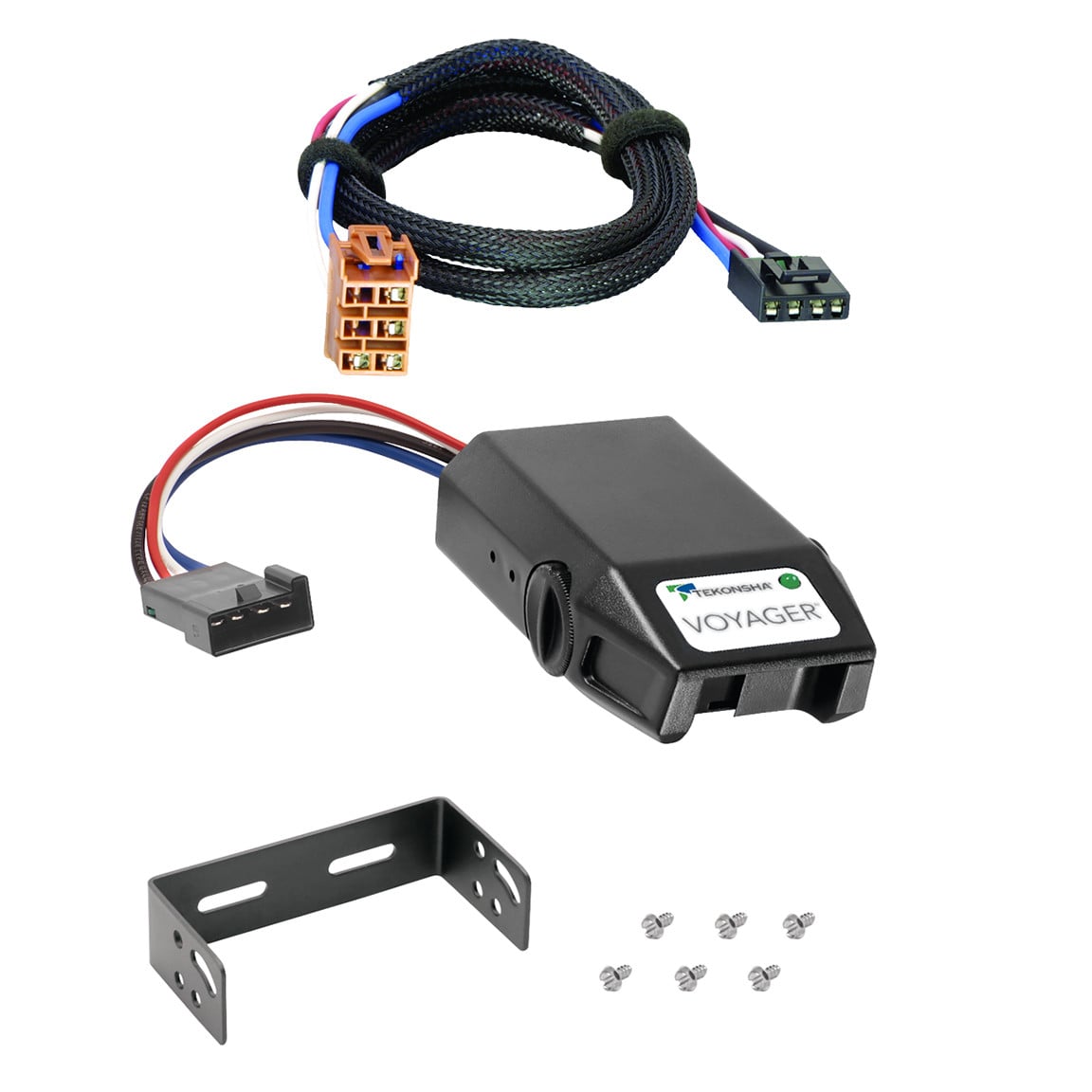
The Tekonsha Voyager electric brake controller provides secure trailer braking when you need it most. As a tried-and-true proportional brake controller, the Voyager utilizes patented braking sensor technology and advanced electronics to provide a smooth braking response in any stopping situation. Its bi-colored LED brake indicator assures a complete connection between your vehicle and trailer, with the color changing gradually from green, which notes a completed circuit, to red to indicate relative braking power. This versatile controller has a compact design, a conveniently located power control knob to adjust settings, and a simple level knob for easy leveling during installation. Plus, the Voyager has a Plug & Play feature that allows for quick and easy connection with your vehicle?s wiring. The Tekonsha Voyager trailer brake controller works with 1-4 axle trailers, comes with all the mounting hardware needed for installation, and is backed by a five-year limited warranty.
| BRAND: | TEKONSHA |
| PART NUMBER: | 9030 |
| WARRANTY: | Limited 5 Year Warranty |
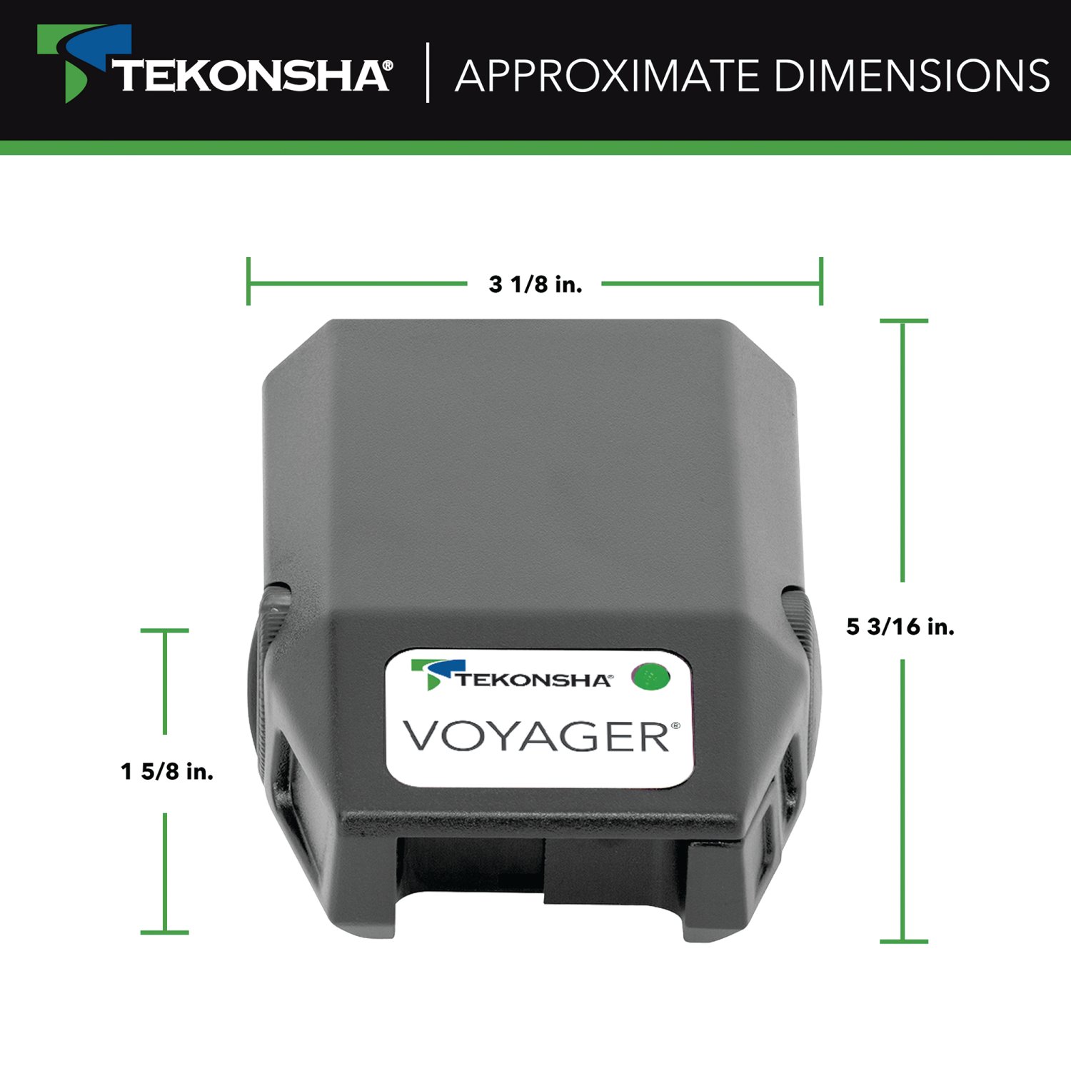
| WEIGHT: | 0.7 LBS |
| MATERIAL: | PLASTIC |
| BRAKE CONTROL TYPE: | PROPORTIONAL |
| TRAILER BRAKE WHEEL QUANTITY: | UP TO EIGHT WHEELS |
| LEVELING CAPABLE: | YES |
| BRAKE TYPE: | Electric |
| Diagnostic Capable: | YES |
| DISPLAY TYPE: | LED OUTPUT |
| HYDRAULIC CONNECTIONS: | NO |
| SOLID STATE CONSTRUCTION: | YES |
| CIRCUIT BREAKER PROTECTED: | YES |
| HOUSING COLOR: | BLACK |
| BRACKET INCLUDED: | YES |

Tekonsha is a leading manufacturer of electronic trailer brake controllers, pioneering the category in the 1970s. The lineup spans proportional units such as the Prodigy P3 and Prodigy iD, time-delayed controllers, the wireless Prodigy RF, plus vehicle-specific wiring harnesses, adapters and trailer brake components engineered for smooth, predictable stopping at any speed.
Tekonsha Engineering Company began in 1964 building RV steps and mirrors. Within a few years it had found its real calling, and by the 1970s Tekonsha was pioneering the manufacture of electronic trailer brake controllers, the product category that still defines the brand. More than half a century later it remains the reference name in trailer braking and is part of the Horizon Global group alongside Reese, Draw-Tite, Fulton, Bulldog and Wesbar.
A brake controller is the component that tells a trailer's electric brakes how hard to work and when, and getting that right is the difference between a controlled stop and a shove from behind. Tekonsha builds both major types. Proportional controllers use an internal accelerometer to sense how quickly the tow vehicle is slowing and apply trailer braking to match, so light braking stays light and hard braking is immediate. Time-delayed controllers ramp to a preset output over a fixed interval, a simpler and more economical approach that suits occasional towing.
The current brake controller range covers most of that ground. The Prodigy iD pairs with a phone through Tekonsha's EDGE technology for setup and monitoring, the P3 offers storable settings for multiple trailers and a trilingual colour LED display, the Prodigy P2 adds a dimmable display and boost mode for heavier loads, and the Voyager keeps operation simple and dependable. The Prodigy RF mounts to the trailer itself and controls wirelessly, which suits rental fleets and drivers who swap tow vehicles.
Installation is supported by vehicle-specific brake control harnesses that plug into a factory connector rather than requiring cut-and-splice wiring, along with mounting brackets and adapters. Matched controller bundles pair a unit with the correct harness. Products are tested to meet and often exceed published industry standards.
Experts available to answer your questions
Call 888-634-94941 compatible vehicles
| Year | Make & Model | Notes |
|---|---|---|
| 2003 - 2006 | Cadillac Escalade ESV | — |
The 2003-2006 Cadillac Escalade ESV Tekonsha Voyager Proportional Brake Controller for Trailers with 1 to 4 Axles Black 9030 (Part #9030 70164) fits the following vehicles: 2003-2006 Cadillac Escalade ESV. Always verify your specific year, make, and model before ordering.
Yes, the 2003-2006 Cadillac Escalade ESV Tekonsha Voyager Proportional Brake Controller for Trailers with 1 to 4 Axles Black 9030 (Part #9030 70164) is designed to fit the 2003-2006 Cadillac Escalade ESV.
The 2003-2006 Cadillac Escalade ESV Tekonsha Voyager Proportional Brake Controller for Trailers with 1 to 4 Axles Black 9030 (Part #9030 70164) fits 2003-2006 Cadillac Escalade ESV models. The 2006 model year is the last year covered by this part number. For newer models, check for an updated version.
The 2003-2006 Cadillac Escalade ESV Tekonsha Voyager Proportional Brake Controller for Trailers with 1 to 4 Axles Black 9030 (Part #9030 70164) Refer to the included instructions for installation details. Basic hand tools are typically all you need.
The N9030 is an electronic brake control designed specifically for use with electric trailer brakes on trailers with 2, 4, 6, or 8 brake applications. It activates by inertia, sensing deceleration and generating an output that reflects the inertia sensed. It can be controlled manually via the slide knob or automatically via the tow vehicle's brake pedal.
No. The N9030 is specifically designed for use with electric trailer brakes only. It is not compatible with surge brakes or other brake types.
The brake control must be mounted between -20 degrees nose down and 70 degrees nose up. Failure to install within these constraints may cause the control to become inoperable.
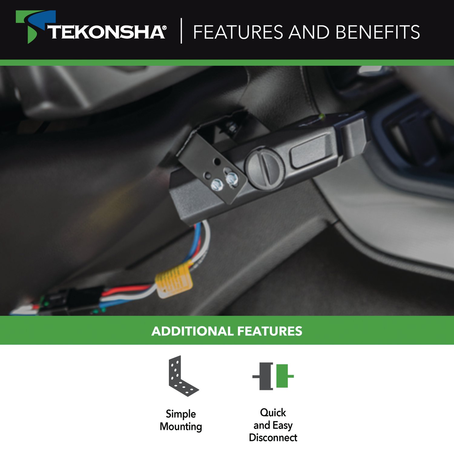
The control includes #6 x 3/8" screws for bracket mounting. Do not use longer screws or drill additional holes, as this may damage the unit.
Drilling is not required if you use the supplied #6 x 3/8" screws in the existing mounting holes. However, drilling or using longer screws may damage the unit and is not recommended.
Reversing the connection to a breakaway battery on the trailer will destroy the brake control. Ensure correct polarity before connecting.
No. You must disconnect the trailer plug from the tow vehicle prior to testing a breakaway switch, or you may destroy the brake control.
Power should never be set high enough to cause trailer brakes to lock up. Skidding trailer wheels can cause loss of directional stability of the trailer and tow vehicle. Set power to a point just below wheel lockup or at sufficient force to achieve maximum braking power without locking.
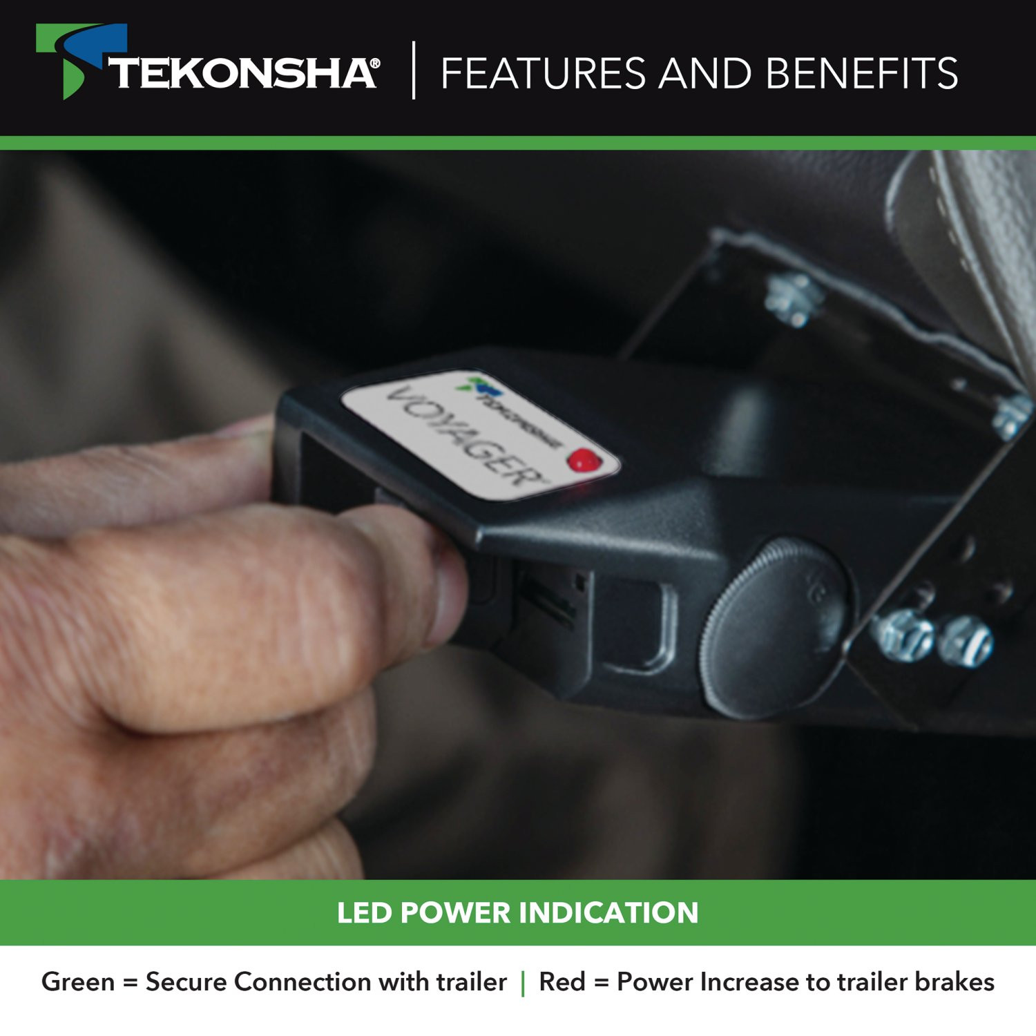
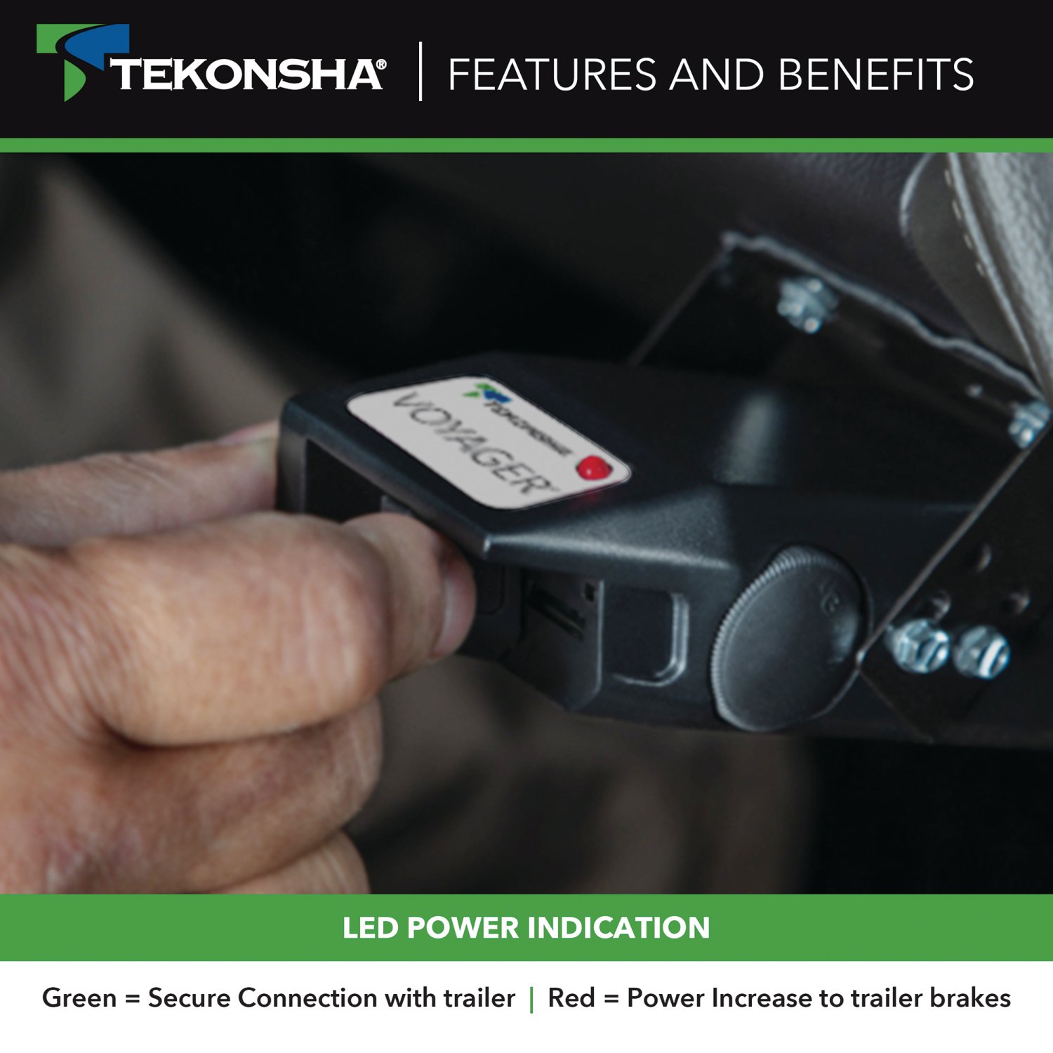
The bi-colored light shows: GREEN when the trailer is connected (normal standby state), and RED when the brake pedal or manual slide knob is activated and the trailer is connected. The light may also show orange shades during level adjustment. The GREEN light draws only 5 milliamperes of current from the tow vehicle—it would take over 10,000 hours to drain the tow vehicle battery.
No. Do not mount or activate RF generating items such as cell phones or two-way radios within 12 inches of the brake control, as they may interfere with its operation.
Mount the bracket securely to a solid surface. The mounting surface must be rigid enough to support the control and maintain its angle within the -20 to +70 degree range during operation.
Tighten the #6 x 3/8" screws until snug. Do not over-tighten, as this may damage the unit. The screws should be tight enough to prevent movement but not so tight as to strip the threads or crack the mounting holes.
After securely mounting the bracket, you must set the level adjustment. Connect the trailer to the tow vehicle (the bi-colored light should glow GREEN), set the power knob to maximum by rotating it fully clockwise, then depress the tow vehicle's brake pedal and hold it while adjusting the level knob.
1. Connect trailer to tow vehicle; the light should be GREEN. 2. Set power knob to maximum (fully clockwise). 3. Depress and hold the tow vehicle's brake pedal. 4. Rotate the level knob counter-clockwise (toward the back) until the light starts to change from GREEN to RED. 5. Carefully rotate the level knob clockwise (toward the front) until ORANGE appears. The light should show DIM ORANGE for typical, BRIGHT ORANGE for aggressive, or DIM RED for more aggressive settings. 6. Release the brake pedal. The trailer and tow vehicle must be parked on a level surface during this procedure.
The range of adjustment for the level knob from DIM ORANGE to DIM RED is 20 degrees of rotation.
1. Connect trailer to tow vehicle. 2. Set power knob to 12 o'clock position. 3. Drive on a dry, level paved surface at 25 mph and apply the manual slide knob. 4. If trailer brakes lock up, turn power down (rotate counter-clockwise toward 8 o'clock). If braking is insufficient, turn power up (rotate clockwise toward 5 o'clock). 5. Repeat until power is set just below wheel lockup or at sufficient force for maximum braking. 6. Make low-speed stops using the brake pedal to verify power and level adjustments. Automatic braking is initiated and terminated via the stoplight switch.
Yes. Always warm the trailer's brakes before setting the power. Warm trailer brakes tend to be more responsive than cold brakes. To warm them, drive a short distance (1/4 mile) at 45 mph with the manual lever engaged enough to cause trailer braking at a low level.
Fine tuning is done after power has been set. Make several slow (25 mph) stops as if coming to a stop sign and observe how the trailer brakes respond. If brakes grab too much (aggressive setting), rotate the level knob clockwise toward you. If the trailer tends to push the tow vehicle (delayed setting), rotate the level knob counter-clockwise away from you. Repeat until desired trailer braking is achieved.
When the brake control is leveled properly, there will be very little current flowing through the brake magnets in a static state with the foot pedal depressed. The brake magnets will hum when there is current flowing through them. Anytime the bi-colored light shows any color other than GREEN, there is current flowing through the brake magnets. Additionally, when power is set correctly, you should feel unified braking between the trailer and tow vehicle.
The level adjustment is critical because it determines whether the automatic braking response is delayed or aggressive. Improper level adjustment causes the braking response to be too harsh or ineffective. The brake control is activated by inertia and requires the level to be set properly, or braking response will be compromised.
GCWR is the Gross Combined Weight Rating—the maximum combined weight of the tow vehicle and trailer. The GCWR must never exceed the vehicle manufacturer's recommendation. Exceeding this rating can compromise braking performance and vehicle safety.
The N9030 is activated by inertia. It senses deceleration and generates an output that reflects the inertia sensed. In a stationary state, the brake control will not apply the trailer brakes unless the manual slide knob is actuated. When the tow vehicle is moving and the brake pedal is depressed, the stoplight switch signals the control to apply trailer brakes proportional to the deceleration sensed.
If the tow vehicle is connected to the trailer but there is no GREEN light, check for: 1. Corrosion on the trailer plug contact—clean if necessary. 2. Loose POWER or GROUND connection—verify all connections are tight and secure.
If the trailer is connected and the light is GREEN but no RED light appears when the manual slide knob is activated, the probable causes are: 1. POWER set at or near minimum—increase power setting. 2. Short on BRAKE line (BLUE wire)—check for damaged wiring. 3. BLACK and WHITE wires reversed—control may be destroyed. 4. 12 volts from external source on BRAKE line (BLUE wire)—check for interference.
If the light is dim RED or flashing RED when the manual slide knob is activated, the probable causes are: 1. Open on GROUND line (WHITE wire)—check for broken or disconnected wiring. 2. Short on BRAKE line (BLUE wire)—inspect wiring for damage or pinching.
If the light glows dim RED and becomes brighter as the power knob is decreased, the probable causes are: 1. Short on BRAKE line (BLUE wire)—check for damaged or pinched wiring. 2. Defective brake magnets—the control may need replacement.
If braking with the foot pedal is too aggressive, the probable causes are: 1. Sensor set too aggressive—adjust the level knob clockwise (toward you) to reduce aggressiveness. 2. Power set too high—reduce the power setting by rotating the power knob counter-clockwise toward the 8 o'clock position.
If braking is delayed for an extended period, the probable causes are: 1. Sensor set improperly—refer to the leveling sensor section and re-level the control. 2. Power set too low—increase the power setting by rotating the power knob clockwise toward the 5 o'clock position.
If the trailer is connected, the light is GREEN, but no RED light appears when the brake pedal is depressed, check: 1. Vehicle not moving—the control requires vehicle movement to apply brakes via the brake pedal. 2. No signal from brake light—test voltage on the RED wire. 3. Sensor set improperly—refer to leveling sensor section. 4. Bad connection on RED wire—verify all connections are secure. 5. Blown stoplight fuse—check and replace if necessary.
Trailer brakes should be adjusted after the first 200 miles of operation when the brake shoes and drums have "seated," and then at 3,000 mile intervals, or as use and performance requires.
1. Jack up the trailer and secure it on adequate capacity jack stands, following the trailer manufacturer's recommendations. Check that wheels and drums rotate freely. 2. Remove the adjusting hole cover from the adjusting slot on the bottom of the brake backing plate. 3. With a screwdriver or standard adjusting tool, rotate the starwheel of the adjuster assembly to expand the brake shoes until the wheel is very difficult to turn. 4. Rotate the starwheel in the opposite direction until the wheel turns freely with slight lining drag. 5. Replace the adjusting hole cover and lower the wheel to the ground. 6. Repeat on all brakes. Never crawl under the trailer unless it is resting on properly placed jack stands.
For drop spindle axles, a modified adjusting tool with approximately an 80 degree angle should be used instead of a standard adjusting tool.
When adjusting trailer brakes: 1. Jack up the trailer and secure it on adequate capacity jack stands following the trailer manufacturer's recommendations. 2. Never lift or support the trailer on any part of the axle or suspension system. 3. Never crawl under the trailer unless it is resting on properly placed jack stands. 4. Verify that wheels and drums rotate freely before and after adjustment.
If you are unsure about the proper setting procedures, review the steps starting at "Leveling the Sensor" through "Fine Tuning," or consult the tow card included with your brake control. You can also contact Tekonsha for technical assistance at 1-888-785-5832 or www.tekonsha.com.
Yes. The front of the brake control must be horizontal, and the control must be parallel to the direction of travel. This orientation is necessary for proper sensor operation and accurate inertia sensing.
Yes. The power may need to be adjusted for different load weights and road conditions. After initial setup, you may need to fine-tune the power setting depending on how heavily the trailer is loaded and the road conditions you encounter.
Not all trailer brakes will lock up due to various conditions. However, inability to lock up the brakes generally indicates the need for an inspection to determine the cause. This may indicate worn brake linings, improper brake adjustment, or other mechanical issues with the trailer brake system.
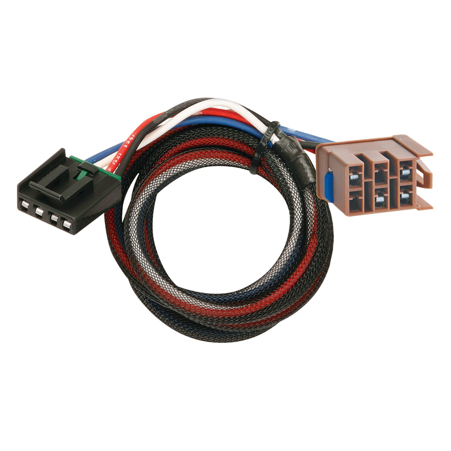
The adapter is designed for vehicles equipped with a black Electric Junction Box located underneath the dashboard, left of the steering column, just above the carpet. All vehicles with this factory provision have a location for the adapter, but not all have complete connections to the battery and wiring to the rear for electric trailer brakes. To confirm fitment, locate the Electric Junction Box and check for the mating connection point in the top row, second from the left. If you cannot locate this box or connection point, the adapter may not be compatible with your vehicle. Consult your vehicle's owner's manual or contact the manufacturer for confirmation.
The adapter (part number 18283-037) is a connector that plugs into your vehicle's factory Electric Junction Box to enable electric trailer brake control. It serves as the interface between your vehicle's electrical system and an electric brake control unit, allowing you to control trailer brakes from inside the vehicle. The adapter must be plugged into the mating receptacle on the backside of the brake control before attaching to the vehicle connector.
The black Electric Junction Box is located in the interior of the vehicle underneath the dashboard, left of the steering column, just above the carpet. You will need to remove the cover to access the mating connection point for electric trailer brakes, which is located in the top row, second from the left.
First, plug the brake control adapter into the mating receptacle on the backside of the brake control unit. Then, plug the adapter into the mating connection in the Electric Junction Box. This sequence ensures proper connection before the adapter is attached to the vehicle connector.
After plugging the brake control adapter into the mating connection in the Electric Junction Box, carefully probe the adapter with a circuit tester to verify that battery (+) power is supplied to it. This confirms the adapter is receiving power from the vehicle's electrical system.
If your vehicle has no power supply to or from the Electric Brake Control Adapter, you must use an Electric Brake Control Wiring Kit. This kit includes the necessary wires and components to route power from the vehicle's electrical system to the adapter. Follow the wiring kit installation instructions to route all wires to the wire locations provided, or follow the brake control manufacturer's instructions.
Open the vehicle's hood and locate the black Electrical Center Box on the driver's side. Remove the box lid and cover to expose the vehicle's brake control feed wire (blue). This will require temporary removal of the vehicle's support brace. Attach and route all wires as described in the wiring kit installation instructions.
In the same location as the brake control feed wire, locate the vehicle's battery (+) supply wire (red) in the black Electrical Center Box on the driver's side. Attach and route all wires as described in the wiring kit installation instructions. After installing the wiring kit, reinstall the Electrical Center Box cover, lid, and support brace.
Yes. An in-line fuse or circuit breaker is required for the Electric Brake Control Wiring Kit installation. This protects the circuit from overload and fire hazard.
After plugging the brake control adapter into the vehicle's electric brake control harness connector, follow all brake control manufacturer's installation instructions. Complete the installation per the electric brake control manufacturer's instructions, mount the unit as directed, and perform all test procedures as instructed by the brake control manufacturer.
Do not exceed the lower of your towing manufacturer's rating or the following: maximum 4 axles with 8 brakes (24 amps). Overloading the circuit can cause fires. Consult your vehicle's owner's manual and instruction sheet for additional information about your specific towing capacity.
Perform all test procedures as instructed by the electric brake control manufacturer. The manual does not specify the exact tests, so refer to your brake control unit's installation instructions for the complete testing procedure.
No. The adapter requires a factory black Electric Junction Box underneath the dashboard, left of the steering column. Not all vehicles have this provision or complete electrical connections for electric trailer brakes. Locate the junction box to confirm compatibility.
An in-line fuse or circuit breaker is required only if you are using an Electric Brake Control Wiring Kit to complete the installation. If your vehicle already has complete connections to the battery and wiring to the rear, no additional fuse is required for the adapter itself.
Plug the adapter into the backside of the brake control unit first, then plug it into the Electric Junction Box in your vehicle. Do not reverse this order.
Maximum 4 axles with 8 brakes (24 amps). Do not exceed this limit or your towing manufacturer's rating, whichever is lower, as overloading can cause fires.
Yes, if you are using an Electric Brake Control Wiring Kit, you must temporarily remove the vehicle's support brace to access the Electrical Center Box and the brake control feed wire (blue). Reinstall it after completing the wiring kit installation.
Free Shipping
Ships free on all orders
 Authorized Dealer


FREE ShippingFREE SHIPPING
Estimated delivery Mon, Sep 28 - Thu, Oct 1
Order before 2 PM EST Monday–Friday for same-day processing
Guaranteed safe & secure checkout
No reviews have been added for this product.