Ask a Question About This Product
Our in-house experts typically reply within one business day.
Reese


Always the correct part
We know our products
Quality Products
Free Shipping!


Always the correct part
We know our products
Quality Products
Free Shipping!
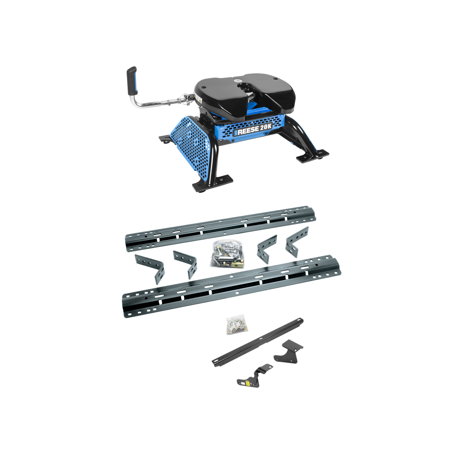
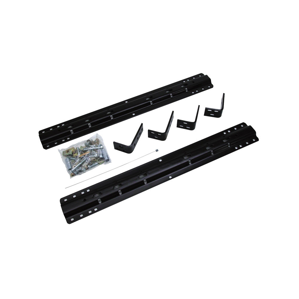
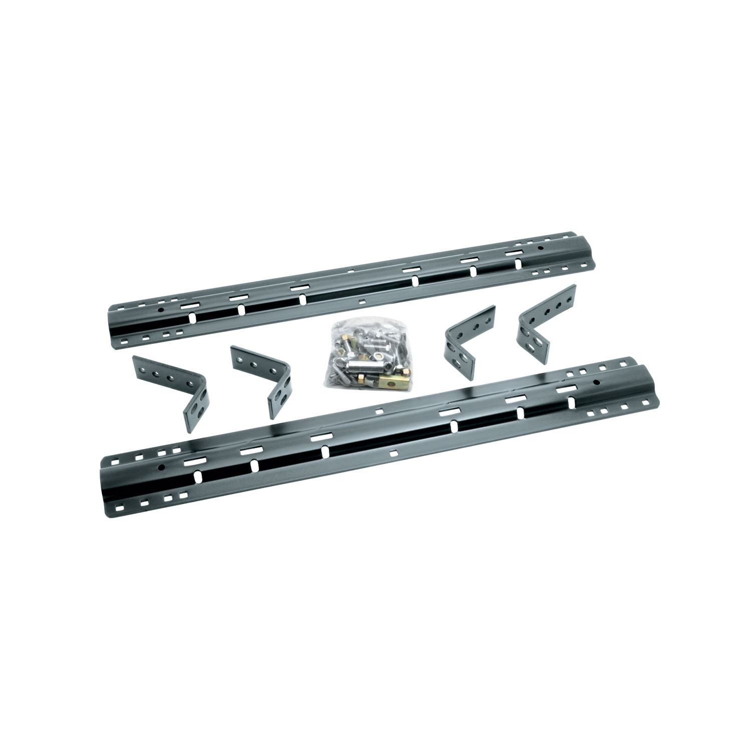
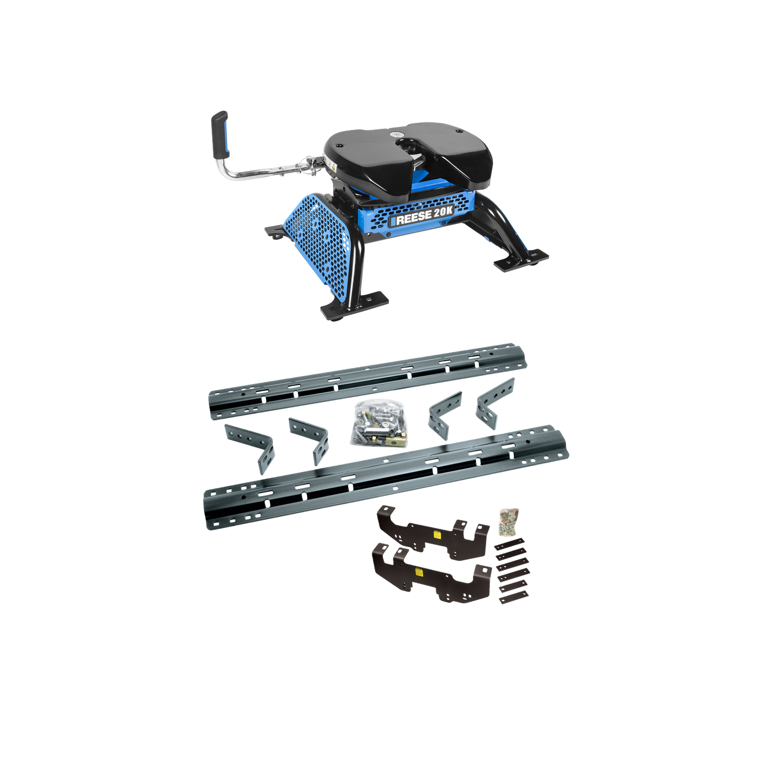
Complete kit bundle containing all necessary components for your project. Professional-grade components designed for reliable performance and long-lasting durability.
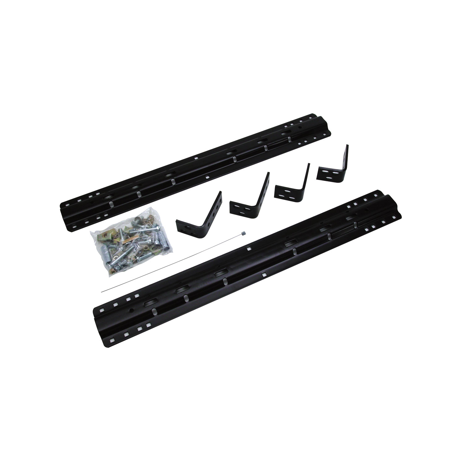
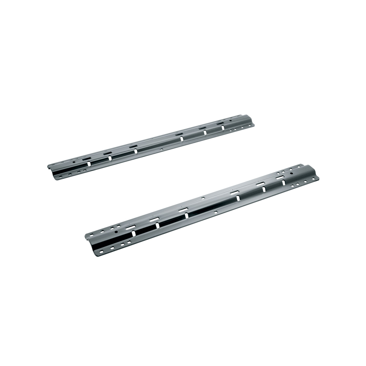
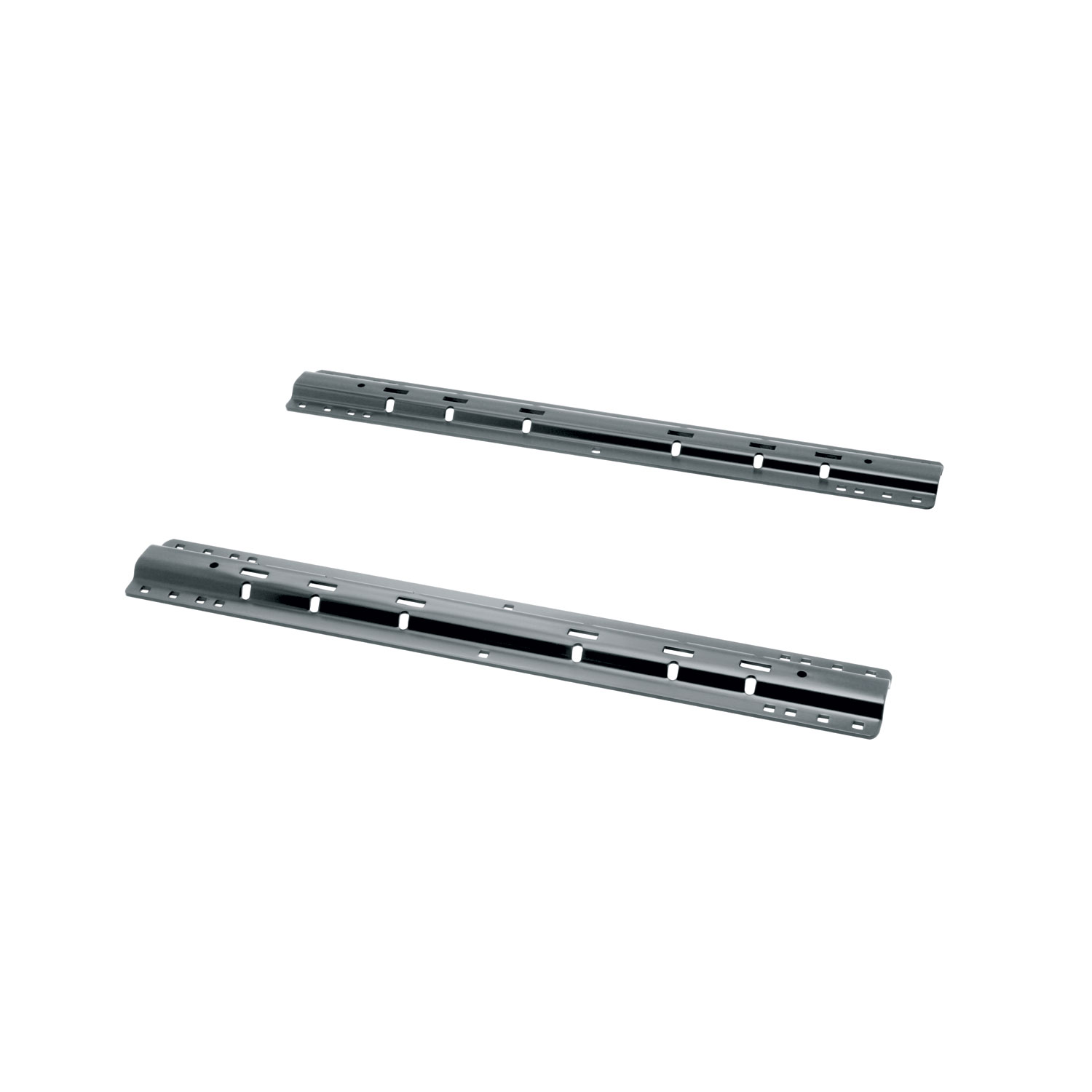
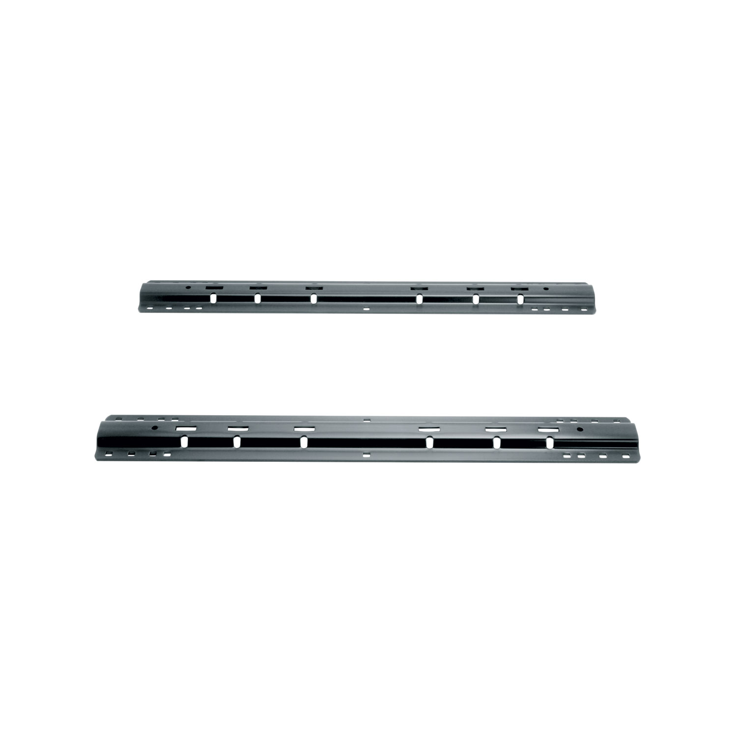
Want to take the family on a cross-country adventure? Or perhaps you're planning a shorter trip to your favorite campground. Whatever your destination, it's important to have the right equipment, especially when towing a fifth wheel trailer. To ensure proper hookup and safety while towing, you'll need something to attach your fifth wheel hitch in the bed on your truck. Many pickups come equipped with factory-installed rails or puck systems, but if you don't have one of these already installed, don't worry. REESE has an extensive line of mounting rails and bracket kits, custom-made to the exact specifications needed based on your truck's year, make, and model. REESE also offers several Industry Standard designs, as well as fastener kits, spacer kits, and a Power Puck mounting kit, so you can be sure you're covered, no matter what pickup you're using to tow. So make it easy. Make it fun. Make it REESE, so you can make the journey as enjoyable as the destination.
| BRAND: | REESE |
| PART NUMBER: | 30035 |
| WARRANTY: | LIMITED 10 YEAR WARRANTY |
| WEIGHT: | 53.5 LBS |
| UNIVERSAL OR SPECIFIC FIT: | UNIVERSAL |
| WELDING REQUIRED: | NO |
| MOUNTING HARDWARE INCLUDED: | YES |
| RAILS INCLUDED: | YES |
| DRILLING REQUIRED: | YES |
| MATERIAL: | STEEL |
| BOLT GRADE: | GRADE 5 |
| LOCKABLE: | NO |
| COLOR: | BLACK |
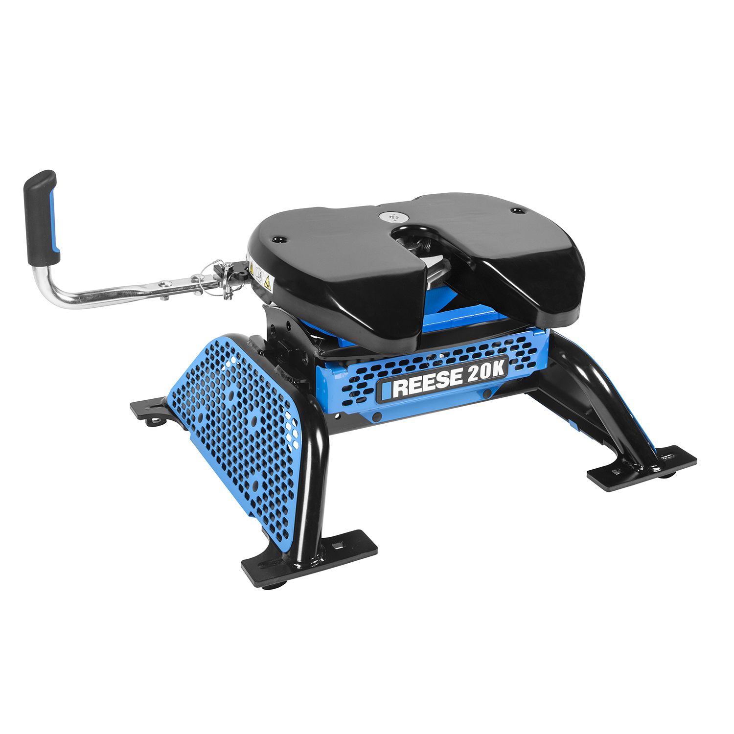
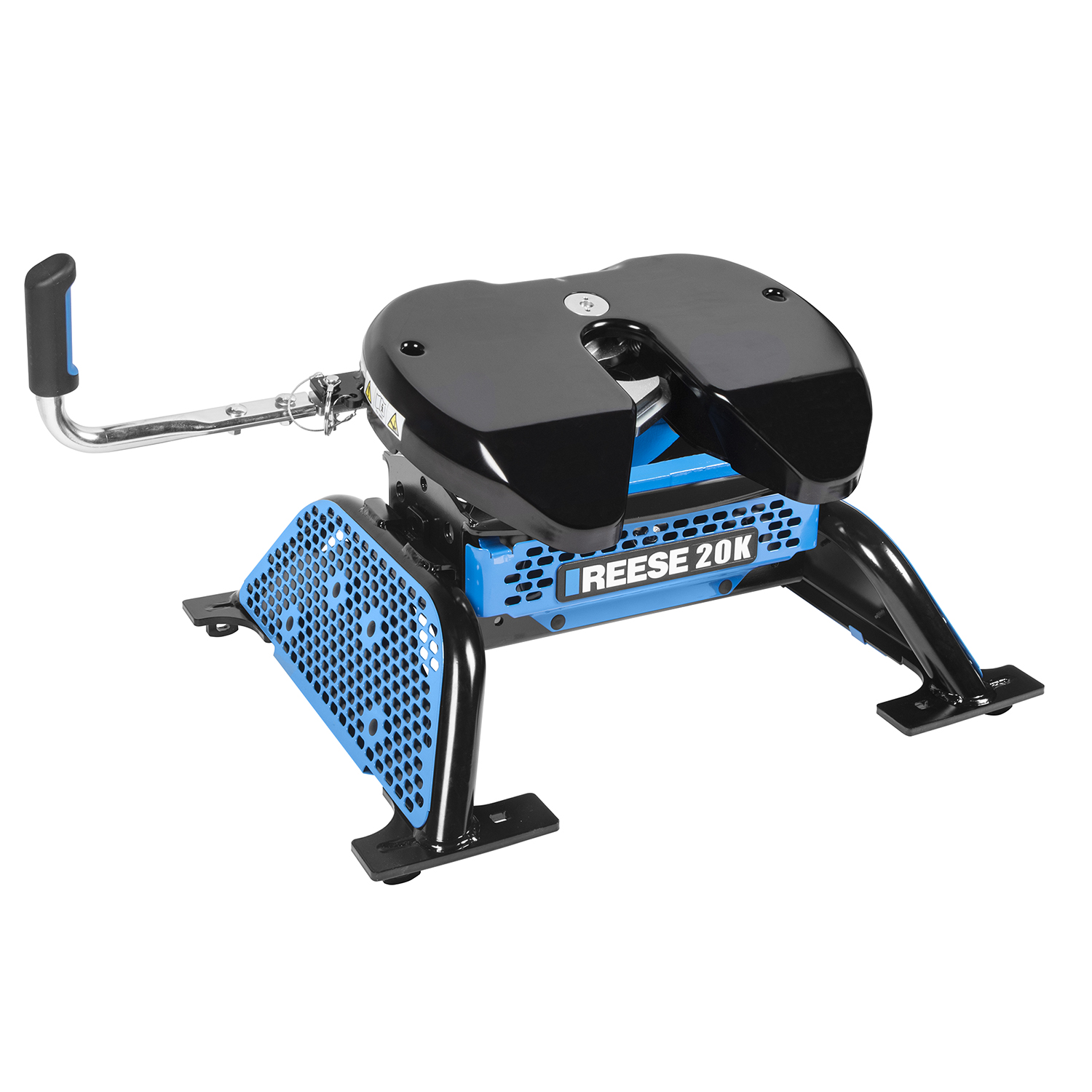
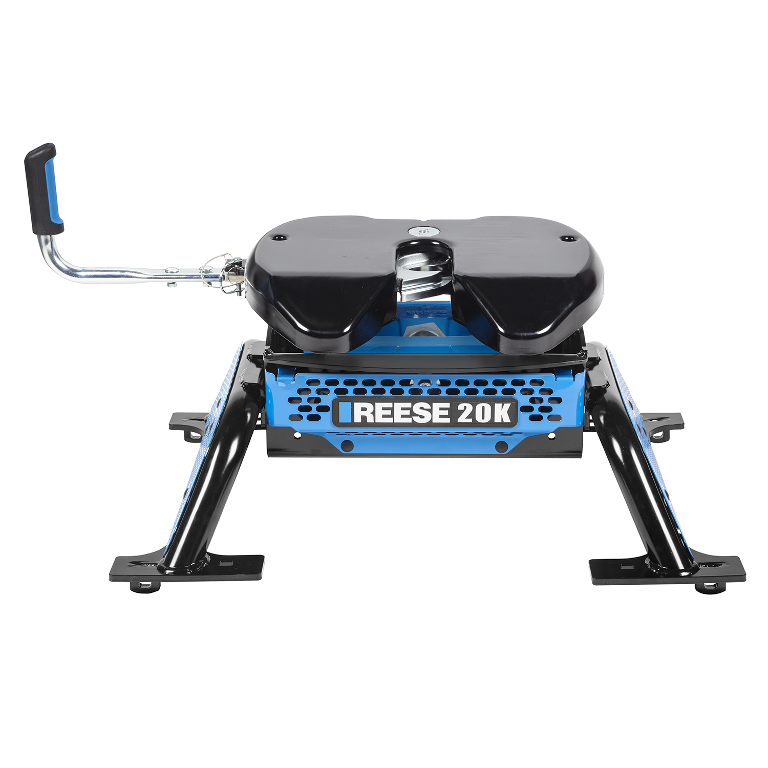
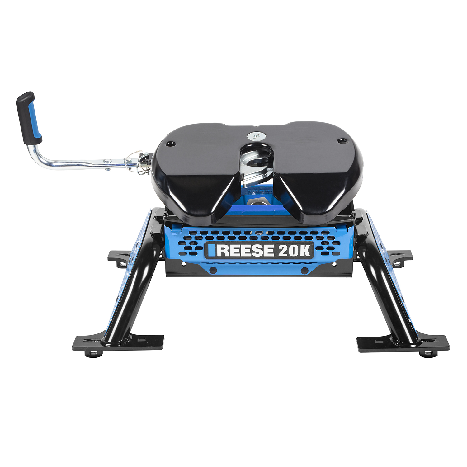
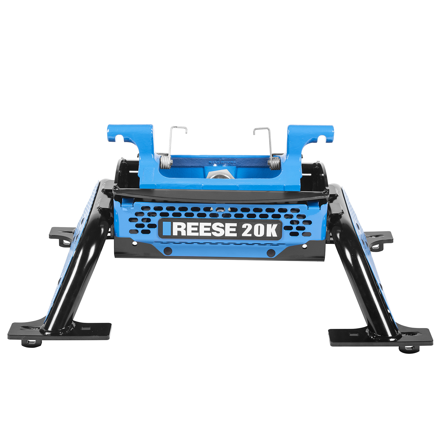
The name you know and the brand you trust brings you the latest in fifth wheel towing: the REESE M5. Whether youre a novice or youve been towing for years, REESE has the hitch you need to connect your truck and trailer safely and securely. Designed with state-of-the-art equipment by top-of-the-line engineers, REESEs complete line of M5 fifth wheel hitches is built to last! Featuring a three-part modular design, with wider stance legs, tighter tolerances, and the industrys best shock absorption system! Plus, an exclusive Talon Jaw that is always ready to receive, gripping the pin to eliminate lateral chucking and reduce sway and noise.
The REESE M5 fifth wheel hitch line combines the latest in technology, rugged endurance, and a sleek design for a quick hook-up and strong performance while on the road, with a clear tow/no tow indicator so you know when your connection is secure, and an ergonomic, easy-reach handle that requires less force to operate. When youre done towing, REESEs fifth wheel hitches are easy to remove, giving you access to the bed of your truck in no time. So tow with the confidence that only REESE can provide and make the journey as enjoyable as the destination.
| BRAND: | REESE |
| PART NUMBER: | 30928 |
| WARRANTY: | LIMITED LIFETIME WARRANTY |
| WEIGHT: | 142.5 LBS |
| CAPACITY: | 20,000 LBS. |
| PIN WEIGHT CAPACITY: | 5,000 LBS. |
| GROSS TOWING WEIGHT: | 20,000 LBS. |
| BASE LENGTH: | 32.26 IN. |
| BASE WIDTH: | 24.68 IN. |
| BASE HEIGHT: | 16.38 IN. |
| VERTICAL ADJUSTMENT: | 14 IN. TO 18 IN. |
| WELDING REQUIRED: | NO |
| LOCKABLE: | YES |
| WIRING HARNESS INCLUDED: | NO |
| JAW TYPE: | SINGLE |
| FORE AND AFT PIVOT: | 15 DEGREE |
| DRILLING REQUIRED: | NO |
| MOUNTING HARDWARE INCLUDED: | NO |
| MOUNTING HOLE QUANTITY: | 4 |
| HITCH TYPE: | STATIONARY |
| MATERIAL: | STEEL |
| SIDE TO SIDE PIVOT: | 15 DEGREES |
| BOLT GRADE: | METRIC 10.9 |
| COLOR: | BLACK/BLUE |
Want to take the family on a cross-country adventure? Or perhaps you're planning a shorter trip to your favorite campground. Whatever your destination, it's important to have the right equipment, especially when towing a fifth wheel trailer. To ensure proper hookup and safety while towing, you'll need something to attach your fifth wheel hitch in the bed on your truck. Many pickups come equipped with factory-installed rails or puck systems, but if you don't have one of these already installed, don't worry. REESE has an extensive line of mounting rails and bracket kits, custom-made to the exact specifications needed based on your truck's year, make, and model. REESE also offers several Industry Standard designs, as well as fastener kits, spacer kits, and a Power Puck mounting kit, so you can be sure you're covered, no matter what pickup you're using to tow. So make it easy. Make it fun. Make it REESE, so you can make the journey as enjoyable as the destination.
| BRAND: | REESE |
| PART NUMBER: | 50142 |
| WARRANTY: | LIMITED 10 YEAR WARRANTY |
| WEIGHT: | 37.55 LBS |
| UNIVERSAL OR SPECIFIC FIT: | SPECIFIC |
| WELDING REQUIRED: | NO |
| MOUNTING HARDWARE INCLUDED: | YES |
| RAILS INCLUDED: | NO |
| DRILLING REQUIRED: | YES |
| MATERIAL: | STEEL |
| BOLT GRADE: | GRADE 5 |
| LOCKABLE: | NO |
| COLOR: | BLACK |
Keywords: RE300353092839255 bundle kit, complete kit, professional components, industrial kit, RE30035, RE30928, RE50142,

Reese has designed towing equipment since 1952 and remains a benchmark for heavy-duty towing. The line covers fifth wheel hitches such as the modular M5, gooseneck couplers including the Goose Box, air-ride and short-bed pin boxes, weight distribution systems with active sway control, and the accessories that connect them, all built to exceed published industry standards.
Reese has been pioneering towing performance since 1952, when Margaret Reese asked her husband TJ to stop travel trailers rocking every time somebody walked through them. His answer, the first pair of stabilising jacks, was simple and effective enough to change the RV industry. From that starting point Reese grew into a designer and manufacturer of complete towing systems, and today it anchors the heavy-duty end of the Horizon Global towing portfolio.
Fifth wheel towing is where the brand's engineering is most visible. The M5 fifth wheel hitch uses a modular design that breaks into manageable sections for assembly, with a wider stance, tighter tolerances and a shock absorption system aimed at the jolts that travel up through a truck bed. For owners who would rather tow from a gooseneck coupler and keep the bed clear, the Goose Box 20K replaces the trailer's king pin with a gooseneck connection carrying its own air-ride cushioning.
Pin boxes are a Reese speciality. The 5th Airborne uses air-ride technology to dampen road shock and reduce the chucking motion that makes fifth wheel towing tiring, while the Sidewinder was designed for short-bed pickups, pivoting the connection point so the trailer can turn sharply without the front cap meeting the cab.
For conventional towing, Reese weight distribution systems restore load to the tow vehicle's front axle and control sway. The Pro Round Bar distributes weight evenly while damping sway, and the Pro Dual Cam II uses active cam-based sway control that works harder the stronger the sway force becomes. Complete kits pair bars, head and shank to a rated tongue weight, and dedicated sway control kits can be added to existing setups. The products suit RV owners, horse and livestock haulers and anyone towing near the upper end of a vehicle's rating.

Experts available to answer your questions
Call 888-634-9494The 30035 is a fifth wheel hitch base rail mounting kit designed to attach fifth wheel hitches to the truck bed of compatible pickup trucks. It is a 10-bolt rail kit that uses Grade 5 bolts, nuts, and washers to secure mounting brackets to the truck frame and bed. The kit includes two base rails, mounting brackets, spacers, carriage bolts, and hardware. It is manufactured by Reese Products (Horizon Global) and is compatible with a wide range of Chevrolet, GMC, Ford, Dodge/RAM, Toyota, and Nissan pickup trucks from 1973 to current models, though specific applications vary by year, cab style, and bed length.
The 30035 is compatible with many Chevrolet, GMC, Ford, Dodge/RAM, Toyota, and Nissan pickup trucks, but fitment depends on the specific year, model, cab style, and bed length. The manual includes detailed installation diagrams for Chevrolet Silverado and GMC Sierra (1973–2016), Ford F-150/F-250/F-350 (1973–2016), Dodge/RAM 1500/2500/3500 (1973–2012), Toyota Tundra (2000–current), Nissan Titan (2004–2015), and Dodge Dakota (1994–2004). Before purchasing, verify your truck's year, model, cab type, and bed length against the manual's vehicle-specific pages (pages 5–17) or visit www.ReeseProducts.com to confirm compatibility. Some applications require additional kits (see page 18).
No, plastic bed liners must be cut out of the way before installation. The manual states: "Do not install mounting rails over plastic bed liners. Plastic bed liners must be cut out of the way." However, spray-in bed liners are permitted. The manual notes: "Base rails may be installed on spray in liner. Note: Consult installer for recommended curing time." If you have a spray-in liner, confirm with the installer that it has cured sufficiently before installation begins.
The minimum bed length is 6 feet without a Reese Sidewinder Pinbox. The manual states: "DO NOT INSTALL ON OR ATTEMPT TO TOW WITH A TRUCK HAVING LESS THAN A 6' BED WITHOUT A REESE SIDEWINDERTM PINBOX INSTALLED ON THE TRAILER." Short bed trucks (with a minimum of 38" from the back of the cab to the axle centerline) require either a 13" extended pin box or a Reese Sidewinder Pinbox for regular maneuvers. If your truck has a bed shorter than 6 feet, you must use a Reese Sidewinder Pinbox on the trailer.
For long bed trucks, the center of the hitch should be at least 52" from the back of the cab to prevent the trailer from hitting the cab when the trailer is turned 90°. The actual distance required depends on the trailer width and king pin location. Short bed trucks (minimum 38" from back of cab to axle centerline) do not require the 52" measurement if equipped with a 13" extended pin box or Reese Sidewinder Pinbox. Always measure your specific truck and trailer before installation to ensure adequate clearance at both the cab and bumper for turns.
A Reese Sidewinder Pinbox is required for certain short-bed and crew-cab applications. Specifically: trucks with beds shorter than 6 feet require a Sidewinder Pinbox on the trailer; 2004–2019 Chevrolet Silverado 1500 crew cabs with ~5'8" beds require a Sidewinder Pinbox; 2004–2014 Ford F-150 and 2015+ Ford F-150 with ~5'2" beds require a Sidewinder Pinbox; 2007+ Toyota Tundra CrewMax with ~5.5' bed requires a Sidewinder Pinbox; and several RAM and Nissan models with ~5'2" beds require a Sidewinder Pinbox. Check page 18 of the manual for your specific truck model and bed length, or visit www.ReeseProducts.com for current vehicle listings.
Some vehicles require additional kits to complete installation. Check page 18 of the manual for your specific truck model. For example: 2000–2006 Toyota Tundra requires kit 58197; 2007+ Toyota Tundra requires kit 58309; 2003–2012 Dodge RAM 2500/3500 with overload brackets requires kit 58186; 2004–2015 Nissan Titan requires kit 58405; 2004–2014 Ford F-150 requires kit 58426N; 2015+ Ford F-150 requires kit 58545N; and several RAM models require kits 58386N, 58520N, 58522N, or 58523N. Do not start installation until you have read the instructions included with any additional kits, as they contain important details.
The following tools are required: 1/8" drill bit, 17/32" drill bit, 3/4" socket and open-end wrench, 100 lb-ft torque wrench, and C-clamps. Some Dodge applications also require a 1" drill bit. A jack and jack stands are needed to raise and support the truck. The manual recommends that the truck be raised high enough to allow jack stands to be placed under the rear spring hanger bracket to provide maximum room for installation.
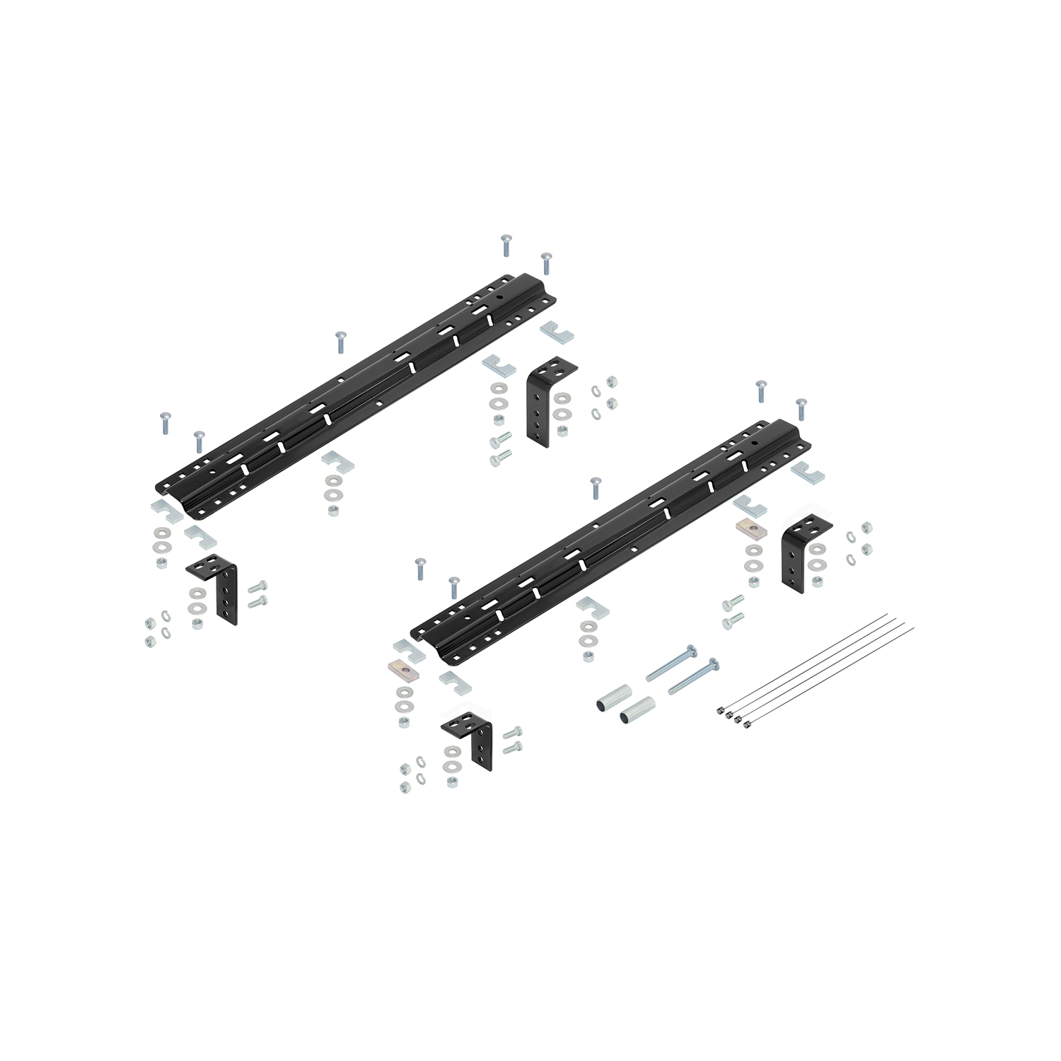
The kit includes: 2 long brackets, 2 short brackets, 10 1/2" spacers, 2 spacers, 10 carriage bolts, 8 knurled bolts, 18 1/2" nuts, 18 1/2" lockwashers, 6 1/2" serrated washers, 4 1/2" flat washers, 2 4-1/2" carriage bolts, 2 tube spacers, 2 base rails, and 1 pull wire. The manual notes: "NOT ALL HARDWARE IS GOING TO BE USED ON ALL INSTALLATIONS." The specific hardware used depends on your vehicle's configuration. All bolts are Grade 5 and nuts are Grade 5 unless specified otherwise.
1. Raise the rear of the truck high enough to allow jack stands to be placed under the rear spring hanger bracket. Ensure the truck is properly blocked and restrained to prevent it from falling. 2. Remove any plastic bed liners; spray-in liners may remain if cured. 3. Familiarize yourself with all parts by checking them against the parts list (Fig. 1). 4. Locate the vehicle-specific installation diagram for your truck model and year (pages 5–17). 5. Before drilling, check for obstructions such as fuel lines, brake lines, and structural members beneath the truck bed. 6. Gather all required tools: 1/8" and 17/32" drill bits, 3/4" socket and open-end wrench, 100 lb-ft torque wrench, and C-clamps.
1. Center the hitch between the fender wells. 2. Make sure the rails are square by adjusting their position until both diagonal measurements (measured from the same reference point on the truck bed) are the same. This ensures the rails are parallel and will allow proper installation of a gooseneck or other fifth wheel. 3. Refer to the vehicle-specific diagram for your truck model (pages 5–17) to determine the correct distance from the rear edge of the truck bed to the rear edge of the base rail. Distances vary by vehicle; for example, 2011–2016 Chevrolet Silverado 2500/3500 HD with an 8' box requires 29¾", while a 6' box requires 25¼". 4. Once positioned correctly, proceed to drilling.
Yes, drilling is required. The installation involves drilling 10 holes in the truck bed and frame. The process is: 1. Drill all 10 holes with a 1/8" drill bit as pilot holes. 2. Temporarily position the frame brackets to the frame and align them with the pilot holes to ensure the brackets and holes in the bed align without interference with any structure below the truck bed. 3. If holes do not align, restart positioning at step 7. 4. Enlarge the pilot holes with a 17/32" drill bit. 5. Install 1/2" carriage bolts into the enlarged holes. Some Dodge applications may also require a 1" drill bit. Always check for obstructions (fuel lines, brake lines, structural members) before drilling.
Three drill bit sizes are used: 1/8" for pilot holes, 17/32" for enlarging holes in the chassis frame, and 1" for some Dodge applications. The manual emphasizes: "It is important that 17/32" drill be used for holes in chassis frame as rib neck bolts may break if too small a hole is used and neck may not grip if too large a hole is used." Always use the correct size to ensure proper bolt grip and prevent bolt failure.
Bracket modifications are required for specific vehicles. For Dodge Dakota (1994–2004), the manual states: "Cut 1" from top flange of brackets. Under bed, mount brackets with flanges facing out." For other vehicles, no cutting is mentioned. However, the manual notes that on some vehicles, long and short brackets may need to be switched or repositioned to avoid interference with exhaust hangers, fuel lines, brake cable hangers, or overload springs. Refer to your vehicle-specific installation diagram (pages 5–17) for any required bracket modifications.
The primary permanent modification is drilling 10 holes in the truck bed and frame. For Dodge Dakota models, cutting 1" from the top flange of brackets is required. Plastic bed liners must be cut away or removed. On some vehicles, brackets may need to be repositioned or switched to avoid interference with factory components. The manual notes that on 2013 RAM 2500 HD, a tube spacer must be dropped through a hole in the truck bed to avoid crushing the bed sill when torquing the 4-1/2" carriage bolt. These modifications are permanent and cannot be easily reversed.
All nuts must be torqued to 85 lb-ft. However, there is one important exception: for 1973–1987 Chevrolet and GMC models (both with outside and inside shock absorbers), the manual states: "DO NOT Torque to 85lb-ft (tighten but do not crush bed sill)." For these older models, tighten the nuts firmly but do not apply full torque to avoid crushing the bed sill. Use a 100 lb-ft torque wrench for all other applications.
The kit uses 1/2" carriage bolts, 1/2"-13x1-3/8" ribbed neck bolts (rib neck bolts), and 4-1/2" carriage bolts. All bolts are Grade 5 unless specified otherwise. The manual states: "Use only HORIZON GLOBAL supplied bolts, nuts, and washers to install this kit. All bolts are Grade 5 and nuts are Grade 5 unless specified otherwise." Rib neck bolts have threads pointing outward and must be lubricated on the knurls only; do not lubricate the threads, as this may cause bolt failure.
Spacers fill corrugations and gaps in the truck bed floor to ensure proper bolt seating and prevent crushing of the bed. The kit includes 1/2" spacers and 5/16" thick slotted spacers. For most vehicles, a 5/16" thick slotted spacer is installed above or below the bed to fill corrugations. For Toyota 2000–2006 Tundra, part #58197 spacer kit is required; stack one 3/16" and one 5/16" thick slotted spacer to avoid crushing the truck bed. For 2013 RAM 2500 HD, a tube spacer is used with the 4-1/2" carriage bolt to attach through the rear bed sill (Row 3) and avoid crushing the bed sill when torquing.
1. Install mounting brackets onto carriage bolts with long brackets on forward bolts and short brackets on rearward bolts. (Long and short brackets can be interchanged as needed for your specific vehicle.) 2. Secure bolts through mounting brackets with serrated washers, lock washers, and hex nuts. 3. Secure the other four bolts through the bed with flat washers, lock washers, and nuts. 4. Drill two holes in the frame for each bracket, selecting the holes that give the greatest spread between bolts. 5. Install eight 1/2"-13x1-3/8" ribbed neck bolts (threads pointing out), lock washers, and hex nuts. Tighten nuts until bolt heads seat. 6. Lubricate the knurls of all rib neck bolts (do not lubricate threads). 7. Torque all nuts to 85 lb-ft. Refer to your vehicle-specific diagram for bracket positioning and row placement.
The pull wire is provided to pull rib neck bolts through the frame as needed per application. On some vehicles, particularly those with tubular frames or complex frame designs, the rib neck bolts cannot be easily inserted from the outside. The pull wire allows the installer to thread the bolts through access holes in the frame. For 2013 RAM 2500 HD, the manual notes: "Rib neck bolts will need to be pulled through access holes in frame with supplied pull wire. Wire extensions will need to be added on to the pull wires for the forward rib bolts." If you encounter difficulty inserting bolts, use the pull wire as directed in your vehicle-specific installation diagram.
The bed sill is a critical structural component, and drilling in the wrong location can cause damage. Follow these steps: 1. Find the parallel rows of bed sill spot welds in the truck bed. 2. Do not drill in the ~4" gap between the parallel rows of spot welds where the bed sill sits. 3. Refer to your vehicle-specific diagram (pages 5–17) to identify the correct rows for drilling. 4. After positioning the rails, temporarily install the frame brackets and align them with pilot holes to ensure they do not interfere with the bed sill. 5. If holes do not align without interference, restart positioning. 6. For 2013 RAM 2500 HD, ensure brackets in Row 2 are close to the rear side of the bed sill as shown in the diagram to avoid interference when drilling in Row 3. Always check for obstructions before drilling.
The manual states: "Must install center bolt in one of the center holes in each rail. Check to make sure center bolt does not interfere with bed sill." This note appears on all vehicle-specific diagrams. The center bolt refers to one of the bolts that passes through the center holes of each base rail. You must select one of the center holes for bolt installation and verify that it does not interfere with the bed sill structure before drilling.
The manual includes a critical warning: "If the truck is raised, be sure that the truck is properly blocked and restrained to prevent the truck from falling. Failure to do so may result in the truck suddenly falling, causing death or serious injury." Specifically: 1. Raise the rear of the truck high enough to allow jack stands to be placed under the rear spring hanger bracket. 2. Use jack stands to support the truck; do not rely on a jack alone. 3. Ensure the truck is properly blocked and restrained to prevent it from falling. 4. Never work under a truck supported only by a jack. Always use jack stands as the primary support.
Before drilling, you must check for obstructions beneath the truck bed. The manual states: "Check for obstructions before drilling. Failure to do so could result in damaged fuel or brake lines, structural members, etc." Specifically, check for: fuel lines, brake lines, and structural members. The manual notes: "HORIZON GLOBAL does its best to communicate tow vehicle manufacturer changes; however, it is ultimately the responsibility of the installer to prevent damage due to installation." If you are unsure about what lies beneath the truck bed, consult the truck's service manual or a professional installer.
Lubricate only the knurls of the rib neck bolts. The manual includes a warning: "DO NOT lubricate threads. It may cause bolt failure." The knurls are the ridged portions of the bolt that grip the frame. Lubricating the threads can weaken the bolt and cause it to fail under load. Apply lubricant to the knurled (ridged) surface only, not to the threaded portion.
After installation, perform the following checks: 1. Verify that all nuts are torqued to 85 lb-ft (or tightened firmly without crushing the bed sill for 1973–1987 Chevrolet/GMC models). 2. Ensure the hitch is centered between the fender wells and that both diagonal measurements are the same. 3. Confirm that the center bolt does not interfere with the bed sill. 4. Check that the hitch center is at least 52" from the back of the cab (for long bed trucks) or meets the minimum distance for short bed trucks. 5. Verify that all brackets are properly seated and secure. 6. Check for any interference with suspension components, exhaust hangers, fuel lines, or brake cable hangers. 7. Measure the truck and trailer to ensure adequate clearance at the cab and bumper for turns. The manual states: "Always measure truck and trailer before installing hitch to be sure that there is clearance at the cab and at the bumper to allow for turns."
The manual does not provide a specific maintenance schedule. However, it is recommended that you periodically inspect the installation to ensure all bolts remain tight and that there is no rust or corrosion on the hardware. If you notice any loose bolts, retorque them to 85 lb-ft. For warranty information, the kit is covered by a 10-year limited warranty against defects in material and workmanship under normal use. For specific maintenance recommendations, contact Reese Products at 1-800-632-3290.
If the frame brackets do not align with the holes in the bed after drilling pilot holes, the manual instructs: "If holes do not align with the brackets and rails, restart installation at step 7." This means you must reposition the base rails until both diagonal measurements are the same, ensuring the rails are square and centered between the fender wells. Then repeat the drilling process with new pilot holes. Do not force misaligned brackets, as this can cause improper installation and potential failure.
If rib neck bolts do not fit or grip properly, the hole size is likely incorrect. The manual emphasizes: "It is important that 17/32" drill be used for holes in chassis frame as rib neck bolts may break if too small a hole is used and neck may not grip if too large a hole is used." If holes are too small, the bolt may break; if too large, the knurled neck will not grip. Verify that you used a 17/32" drill bit to enlarge the pilot holes. If the holes are incorrect, you may need to drill new holes in a different location or consult a professional installer. The pull wire provided can help pull bolts through frame access holes if needed.
If the center bolt interferes with the bed sill, you must reposition the base rails. The manual notes on all vehicle-specific diagrams: "Check to make sure center bolt does not interfere with bed sill." If interference occurs, adjust the position of the rails forward or backward (typically +/- 1/2") and re-drill the pilot holes. Ensure both diagonal measurements remain the same to keep the rails square. Do not force a bolt through the bed sill, as this can cause structural damage.
If brackets interfere with exhaust hangers or fuel lines, the manual provides several solutions depending on your vehicle: 1. Switch the positions of the long and short brackets on the driver's side (noted for Ford 1997–2003 F-150 and some other models). 2. Move the base rail location +/- 1/2" to ensure frame brackets do not interfere with bed sills or other components. 3. For some vehicles, reposition forward brackets to Row 2 to avoid brake cable hangers and overload springs. Refer to your vehicle-specific installation diagram (pages 5–17) for recommended bracket positions. If interference persists, consult a professional installer or contact Reese Products at 1-800-632-3290.
The manual notes: "On vehicles with heavy duty suspensions, check for interference with bolts where brackets are mounted to frame. If interference with suspension spring results, cut bolt flush to nut outboard of frame or use weld option." If bolts interfere with suspension springs, you have two options: 1. Cut the bolt flush to the nut on the outboard side of the frame, or 2. Use the optional weld method instead of bolts. Consult your vehicle-specific diagram for the optional weld pattern, or contact a professional installer if you are unsure how to proceed.
If the truck bed is being crushed when torquing bolts, spacers are not being used correctly. The manual states: "Install 5/16" thick slotted spacer above or below bed to fill corrugations in bed floor." Spacers prevent the bed from being crushed by distributing the clamping force. For Toyota 2000–2006 Tundra, stack one 3/16" and one 5/16" thick slotted spacer to avoid crushing. For 2013 RAM 2500 HD, drop a tube spacer through a hole in the truck bed before torquing the 4-1/2" carriage bolt. If crushing has already occurred, stop torquing immediately and verify that spacers are properly installed before continuing. For 1973–1987 Chevrolet/GMC models, do not torque to 85 lb-ft; tighten only until the bolt head seats to avoid crushing the bed sill.
A Reese Sidewinder Pinbox is required for trucks with beds shorter than 6 feet and for certain crew-cab models with ~5'2" beds. Check page 18 of the manual for your specific truck model and bed length, or visit www.ReeseProducts.com.
Required tools: 1/8" and 17/32" drill bits, 3/4" socket and open-end wrench, 100 lb-ft torque wrench, C-clamps, jack, and jack stands. Some Dodge applications also require a 1" drill bit.
Torque all nuts to 85 lb-ft. Exception: for 1973–1987 Chevrolet and GMC models, tighten firmly but do not crush the bed sill (do not apply full 85 lb-ft torque).
Use jack stands to support the truck; never work under a truck supported only by a jack. Ensure the truck is properly blocked and restrained to prevent falling. Check for fuel lines, brake lines, and structural members before drilling. Do not lubricate threads of rib neck bolts; lubricate knurls only.
The minimum bed length is 6 feet without a Reese Sidewinder Pinbox. Short bed trucks require a 13" extended pin box or Reese Sidewinder Pinbox.
Restart installation at step 7 (positioning the rails). Reposition the base rails until both diagonal measurements are the same, ensuring the rails are square and centered between the fender wells. Then repeat the drilling process with new pilot holes. Do not force misaligned brackets, as this can cause improper installation and potential failure.
Verify that you used a 17/32" drill bit to enlarge the pilot holes. The manual states: "It is important that 17/32" drill be used for holes in chassis frame as rib neck bolts may break if too small a hole is used and neck may not grip if too large a hole is used." If holes are too small, the bolt may break; if too large, the knurled neck will not grip. If holes are incorrect, drill new holes in a different location or consult a professional installer. The pull wire provided can help pull bolts through frame access holes if needed.
Reposition the base rails forward or backward (typically +/- 1/2") and re-drill the pilot holes. Ensure both diagonal measurements remain the same to keep the rails square. Do not force a bolt through the bed sill, as this can cause structural damage.
Refer to your vehicle-specific installation diagram (pages 5–17) for recommended bracket positions. Solutions may include: 1. Switching the positions of long and short brackets on the driver's side, 2. Moving the base rail location +/- 1/2", or 3. Repositioning forward brackets to Row 2. If interference persists, consult a professional installer or contact Reese Products at 1-800-632-3290.
If bolts interfere with suspension springs, you have two options: 1. Cut the bolt flush to the nut on the outboard side of the frame, or 2. Use the optional weld method instead of bolts (shown on the vehicle-specific diagram). Consult your vehicle-specific diagram for the optional weld pattern, or contact a professional installer if you are unsure how to proceed.
Stop torquing immediately. Spacers are not being used correctly. Verify that a 5/16" thick slotted spacer is installed above or below the bed to fill corrugations. For Toyota 2000–2006 Tundra, ensure one 3/16" and one 5/16" thick slotted spacer are stacked. For 2013 RAM 2500 HD, ensure a tube spacer is dropped through a hole in the truck bed before torquing the 4-1/2" carriage bolt. For 1973–1987 Chevrolet/GMC models, do not torque to 85 lb-ft; tighten only until the bolt head seats to avoid crushing the bed sill.
The M5 ISR 20K LEGS (part number 30926) are support legs for a 5th wheel hitch system rated for 20,000 lbs towing capacity with a maximum pin weight of 5,000 lbs. The legs attach to the M5 Center Section and provide vertical support for the hitch assembly when mounted on a truck. They must be used together with the M5 Head (part 30892) and M5 Center Section (part 30884).
The M5 ISR 20K LEGS are designed for installation on trucks with existing above-bed rails. The legs attach to the M5 Center Section, which then mounts to these rails using provided pins and spring clips. The manual does not specify which truck models or years are compatible. Contact the manufacturer at 1-800-632-3290 or consult a fitment database to confirm compatibility with your specific vehicle.
No. The M5 ISR 20K LEGS are designed specifically for installation with the M5 Head (part 30892) and M5 Center Section (part 30884). The legs attach to the center section structure and cannot function as a standalone product.
You will need an M24 wrench and a torque wrench. The M24 wrench is used to tighten the handle assembly on the head unit. The torque wrench is required to tighten the M16 hex-head bolts to the specified 220 ft-lb torque value.
The M5 ISR 20K LEGS (part 30926) include: 2 M5 ISR Legs, 4 M16 x 2 x 40mm CL10.9 hex-head bolts, 4 5/8-inch conical washers, 4 half-inch pins, and 4 spring clips. The legs also have 4 holes for anti-rattle accessories, which are sold separately.
Yes. The M5 ISR 20K LEGS come ready to install. No pre-assembly or preparation of the legs themselves is required before attachment to the center section.
A minimum of 6 inches of clearance is required between the truck bed rail and the bottom of the trailer. The legs must be attached at the same height on both sides of the unit. The M5 ISR 20K LEGS provide 4 inches of vertical adjustment to help achieve this clearance. For detailed guidance on matching the hitch, truck, and trailer, refer to the guidelines in the M5 Head and Center Section instruction sheet.
Using the 4 M16 x 2 x 40mm hex-head bolts, attach the legs to the center section structure by threading the bolts from the inside of the center section into the threaded portion of the legs. Finger-tighten the bolts initially until final adjustments are made. Make sure the collars on each leg are completely seated in the corresponding holes in the center section before final tightening.
Once the legs are attached to the center section and the unit is placed in the existing above-bed rails, use the provided half-inch pins to secure the assembly to the rails. Insert the pins through the alignment holes and secure each pin with a spring clip to prevent the pin from coming out. The spring clip must be used on all pins.
Each M16 hex-head bolt that connects the legs to the center section must be tightened to 220 ft-lb of torque. The bolts should be finger-tightened initially until final adjustments are made, then torqued to the final specification once the legs are pinned and securely held in the above-bed rails.
After tightening each M16 hex-head bolt to 220 ft-lb of torque, verify that the hitch is tight to the truck by lifting each side of the hitch. You must also verify that other components of your towing system do not reduce the overall tow rating of the hitch. Once these checks are complete, assemble the head to the center section per the instructions included with the M5 Center Section and Head.
The hitch system is rated for 20,000 lbs towing capacity with a maximum pin weight of 5,000 lbs. However, you must not exceed the towing vehicle manufacturer's recommended towing capacity or the lowest rated component of your system, whichever is lower.
Before any trip, verify that the pins and spring clips are undamaged and secure. Every 1,000 miles, check the M16 hex bolts that connect the center section to the legs to ensure they are still torqued to 220 ft-lb. For general maintenance of the entire 5th wheel hitch assembly, refer to the M5 Head and Center Section instruction sheet.
After tightening the M16 hex-head bolts to 220 ft-lb of torque, lift each side of the hitch to verify it is tight to the truck. The pins and spring clips must be secure and undamaged. Verify that other components of your towing system do not reduce the overall tow rating of the hitch.
The M5 ISR 20K LEGS provide 4 inches of vertical adjustment. This allows you to position the hitch at the correct height to maintain a minimum of 6 inches of clearance between the truck bed rail and the bottom of the trailer.
The M5 ISR 20K LEGS are designed for trucks with existing above-bed rails. The manual does not specify compatible vehicle models. Contact the manufacturer at 1-800-632-3290 or consult a fitment database for your specific truck.
You need an M24 wrench and a torque wrench. The torque wrench must be capable of measuring 220 ft-lb.
No drilling is required. The legs attach to the center section using existing threaded holes and are secured to the truck's above-bed rails using provided pins.
Tighten each M16 hex-head bolt to 220 ft-lb of torque. Check this torque every 1,000 miles during maintenance.
The hitch is rated for 20,000 lbs towing capacity with a maximum pin weight of 5,000 lbs. Do not exceed your vehicle manufacturer's recommended towing capacity.
Check the M16 hex bolts every 1,000 miles to ensure they remain torqued to 220 ft-lb. Before any trip, verify that the pins and spring clips are undamaged and secure.
A minimum of 6 inches of clearance is required between the truck bed rail and the bottom of the trailer. The legs provide 4 inches of vertical adjustment to achieve this.
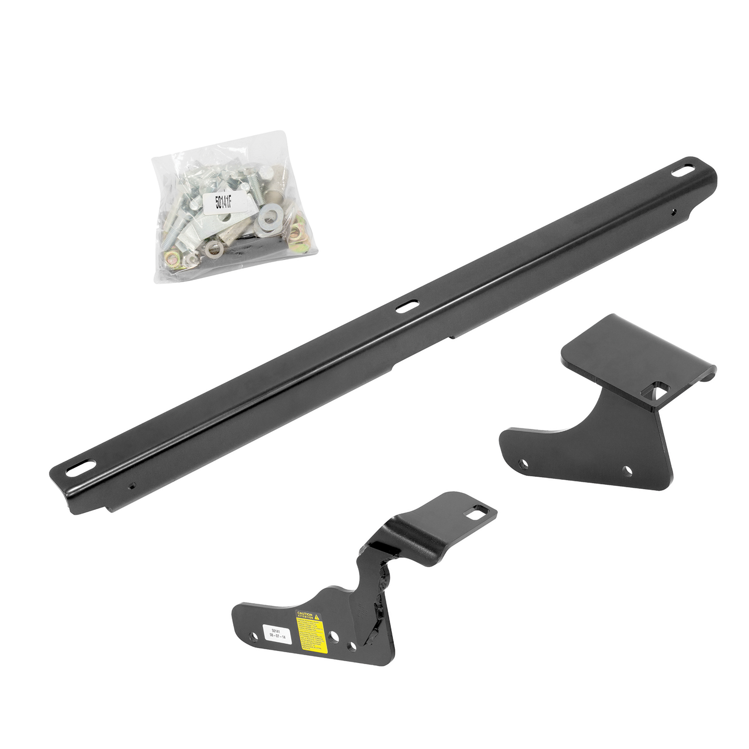
The 50142 is a custom mounting kit designed for Dodge Ram 1500 trucks to support fifth wheel hitches and related towing equipment. It consists of front and rear mounting rails, brackets, spacer plates, and all necessary fasteners. The kit is engineered to attach to the truck bed and frame for secure hitch installation.
The 50142 is designed for Dodge Ram 1500 trucks with bed lengths of 5'7", 6'4", or 8'. It is not recommended for trucks with beds shorter than 6' unless the Sidewinder is used. Always verify your truck's bed length and consult the manual's fitment diagrams on page 4 before purchasing.
Plastic bed liners must be cut out or removed in the areas where the mounting rails attach to allow metal-to-metal contact between the rails and the truck bed. Spray-in bed liners are acceptable and do not need to be removed. Cutting plastic liners is a permanent modification.
Required tools are: wrenches in 3/4", 7/8", and 15/16" sizes; drill bits in 1/8", 9/16", and 5/8" sizes; a 1-1/8" hole saw; a center punch; and a measuring tape. A pull wire is provided with the kit. You will also need a drill and a way to support the exhaust system during installation.
The fastener kit 50142F is listed as required equipment but the manual does not explicitly state whether it is included in the box or must be purchased separately. Contact Reese Products at 1-800-632-3290 to confirm whether 50142F is included with your 50142 kit.
Yes. The manual recommends removing the spare tire to provide better access underneath the vehicle during installation. The spare tire should be reinstalled after all installation steps are complete.
Yes. The plastic inner fender liner must be removed if present on your truck. It should be reinstalled after all installation steps are complete.
The installation sequence is: (1) remove plastic inner fender liner and spare tire; (2) position and mark the rear mounting rail; (3) drill pilot holes and enlarge them; (4) remove exhaust isolators and supports as needed; (5) install the C-channel on the frame cross member; (6) fasten the rear mounting rail to the C-channel; (7) position and mark the front mounting rail; (8) install front frame rail brackets; (9) torque all fasteners in the specified order. Follow steps 1–20 in the manual in sequence.
Center the rear mounting rail left to right on the truck bed floor. Use a measuring tape to locate the correct distance from the rear of the rail to the rear edge of the truck box. The manual provides fitment diagrams on page 4 showing the proper positioning for 5'7", 6'4", and 8' bed lengths. Use a center punch to mark the hole locations per the illustration before drilling.
Yes. Drilling is required. You must drill pilot holes (1/8") through the truck bed at marked locations, then enlarge them to 9/16". You will also drill holes in the frame cross member. A 1-1/8" hole saw may be needed for certain applications. Bare metal should be painted after drilling to prevent rust.
You need drill bits in the following sizes: 1/8" (for pilot holes), 9/16" (to enlarge pilot holes), 5/8" (for frame cross member holes), and a 1-1/8" hole saw. The manual specifies these bit sizes in the Equipment Required section.
Yes, there is a risk. The fuel tank is located below the truck bed on the driver's side. When drilling holes through the bed, you must be careful not to damage the fuel tank or other components underneath. Drill slowly and stop if you encounter resistance. If unsure, consult a qualified technician.
You do not need to remove the entire exhaust system, but you must remove all rubber exhaust isolators rearward of the muffler. Start with the isolator on the forward side of the muffler and work toward the rear. Support the exhaust as required. For dual exhaust systems, you must also unbolt and remove the driver's side exhaust hanger bracket from the cross member. All isolators and brackets must be reinstalled after the mounting kit is secured.
The U-shaped spacer plates (item 13) are used between the C-channel or mounting rails and the truck bed to ensure metal-to-metal contact. This is critical for proper load distribution and structural integrity. Spacer plates must be used at all mounting points where the rails or brackets attach to the bed.
First, temporarily remove the plastic clips holding the wiring harness to the top of the frame cross member and disconnect the electrical connectors at both ends. Remove the rear differential breather tube from the frame cross member and shock mount. Slide the C-channel through the passenger side wheel well and position it approximately centered left to right on the frame cross member. Verify that the 1/8" drilled holes align with the slots in the C-channel. Enlarge the holes to 9/16", paint bare metal, then fasten the C-channel using 5/8" hardware, bolting up through the frame cross member.
Place the unassembled fifth wheel support arches, slider, or goose into the already-installed rear mounting rail. Position the front mounting rail by inserting its tabs into the rear mounting rail and pushing it firmly toward the rear rail. Ensure the front rail is centered on the truck bed. This positioning ensures the fifth wheel will fit snugly. If using multiple hitch products, position both types simultaneously to align the front rail correctly and prevent one product from compromising the fit of the other.
The edge protector (item 17) installs onto the curve section of the driver's side bracket, next to the fuel fill hose. This protects the bracket and hose from damage.
The pull wire (provided with the kit) is used to pull the carriage bolts and square hole plates into the frame when installing the front frame rail brackets. This helps position the brackets correctly and ensures they are seated properly against the truck bed with no gaps.
Torque all 1/2" fasteners to 75 ft-lb (102 N·m). Torque all 5/8" fasteners to 150 ft-lb (204 N·m). Tighten fasteners in this order: (1) hex bolts that fasten the rails to the frame brackets through the bed; (2) hex bolts positioned in the center of the rails; (3) fasteners that attach the frame brackets to the vehicle frame; (4) all remaining fasteners.
All bolts and nuts supplied with the 50142 kit are Grade 5 unless otherwise specified in the parts list. Only the supplied fasteners should be used for installation; do not substitute with fasteners of different grades or specifications.
The manual does not specify which factory fasteners, if any, are reused. All bolts, nuts, and washers needed for the 50142 installation are supplied in the fastener kit 50142F. The manual explicitly states to use only the supplied fasteners for installation.
Yes. After enlarging the drilled holes to their final size, you should paint any bare metal as required to prevent rust and corrosion. This is especially important since the mounting kit will be exposed to weather and road conditions.
When installing the front frame rail brackets, use the supplied U-shaped spacer plates and ensure the brackets are pulled firmly into position using the pull wire. Check that the brackets sit flush against the truck bed with no gaps. This is critical for proper load distribution and structural integrity.
During installation, temporarily remove the plastic clips holding the wiring harness to the top of the frame cross member and disconnect the electrical connectors at both ends of the harness section. Move the harness out of the way to allow the C-channel to be installed. After the C-channel is secured, reattach the wiring harness and reconnect the electrical connectors.
Remove the rear differential breather tube from the vehicle frame cross member and shock mount before installing the C-channel. After the C-channel is secured and all other installation steps are complete, reinstall the breather tube.
Under no circumstances should you exceed the towing vehicle manufacturer's recommended vehicle towing capacity. The 50142 mounting kit is designed to support the truck's factory towing limits, not to increase them. Always consult your Dodge Ram 1500 owner's manual for the maximum towing capacity of your specific truck.
Always measure your truck and trailer before installing the hitch to ensure there is adequate clearance at the cab and at the bumper to allow for turns. The manual does not provide specific clearance measurements, so you must verify clearance with your specific truck and trailer combination. This is the installer's and owner's responsibility.
After installation, verify that: (1) all fasteners are torqued to the specified values (1/2" fasteners to 75 ft-lb, 5/8" fasteners to 150 ft-lb); (2) the spare tire is reinstalled; (3) the wiring harness is reattached and electrical connectors are reconnected; (4) the plastic inner fender liner is reinstalled; (5) all exhaust isolators and brackets are reinstalled; (6) there are no gaps between the frame rail brackets and the truck bed; (7) the mounting rails are centered on the truck bed. The manual does not specify a retorque interval, so consult the manufacturer for maintenance recommendations.
The manual states that installation is the responsibility of the installer and the owner, and that these instructions are guidelines only. The manual does not explicitly require professional installation, but the complexity of the work—including drilling, exhaust removal, and precise torquing—suggests that professional installation is recommended. If you are not experienced with automotive installation, consult a qualified technician.
Yes, the manual notes that if more than one hitch product will be used with the mounting rails, both types should be positioned and aligned at the same time. This ensures that one product does not compromise the fit of the other. Consult the manual or contact Reese Products to confirm compatibility of specific hitch products.
The manual indicates that certain components (item 18, the .25" x 1.5" x 3" block) are "required with diesel engine." This suggests that diesel-powered Ram 1500 trucks may have different mounting requirements or clearances. Verify your truck's engine type and consult the fitment diagrams on page 4 or contact Reese Products to confirm the correct kit configuration for your diesel truck.
The 50142 fits Dodge Ram 1500 trucks with bed lengths of 5'7", 6'4", or 8". Beds shorter than 6' require the Sidewinder. Check your bed length against the fitment diagrams on page 4 of the manual.
You need wrenches (3/4", 7/8", 15/16"), drill bits (1/8", 9/16", 5/8"), a 1-1/8" hole saw, a center punch, measuring tape, and a drill. A pull wire is provided.
Torque 1/2" fasteners to 75 ft-lb (102 N·m) and 5/8" fasteners to 150 ft-lb (204 N·m). Tighten in order: bed-to-frame bolts, center rail bolts, frame bracket bolts, then remaining fasteners.
Yes. Remove the spare tire for access and the plastic inner fender liner if present. Both must be reinstalled after installation.
Plastic bed liners must be cut out to allow metal-to-metal contact. Spray-in liners are acceptable and do not need to be removed.
Do not exceed your vehicle manufacturer's recommended towing capacity. Do not install on beds shorter than 6' unless using the Sidewinder. Ensure adequate clearance at the cab and bumper for turns.


FREE ShippingFREE SHIPPING
Estimated delivery Sun, Oct 18 - Wed, Oct 21
Order before 2 PM EST Monday–Friday for same-day processing
Guaranteed safe & secure checkout
No reviews have been added for this product.