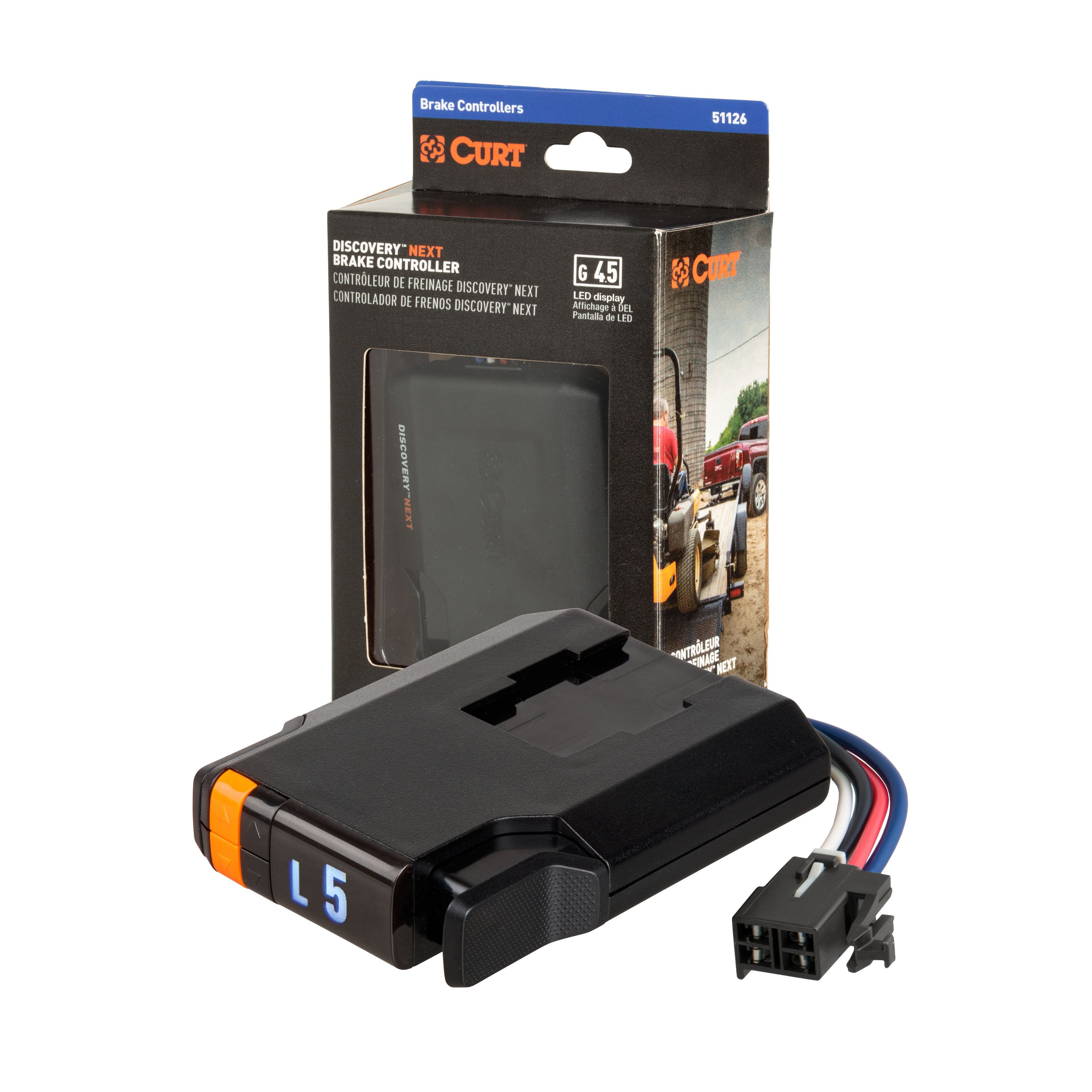
2012-2019 Lincoln MKT CURT Discovery NEXT Time-Delay Trailer Brake Controller 1-4 axlesCURTOriginal price was $131.95. Current price is $113.95.In Stock
View productOur in-house experts typically reply within one business day.

CURT
Verify Fitment
Select your vehicle to confirm this part fits.
2012 - 2019 Lincoln MKT
Confirmed to Fit



Always the correct part
We know our products
Quality Products
Free Shipping!
Always the correct part
We know our products
Quality Products
Free Shipping!
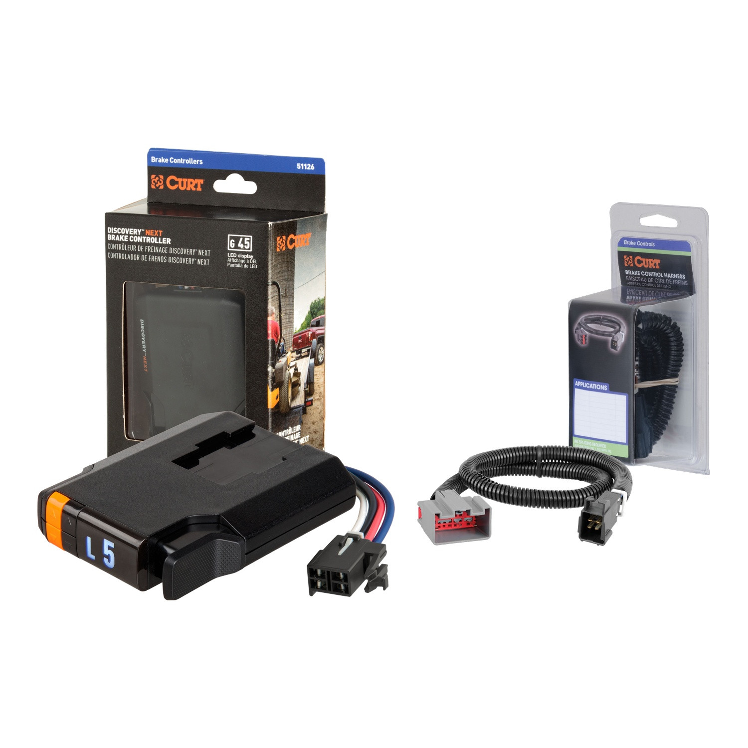
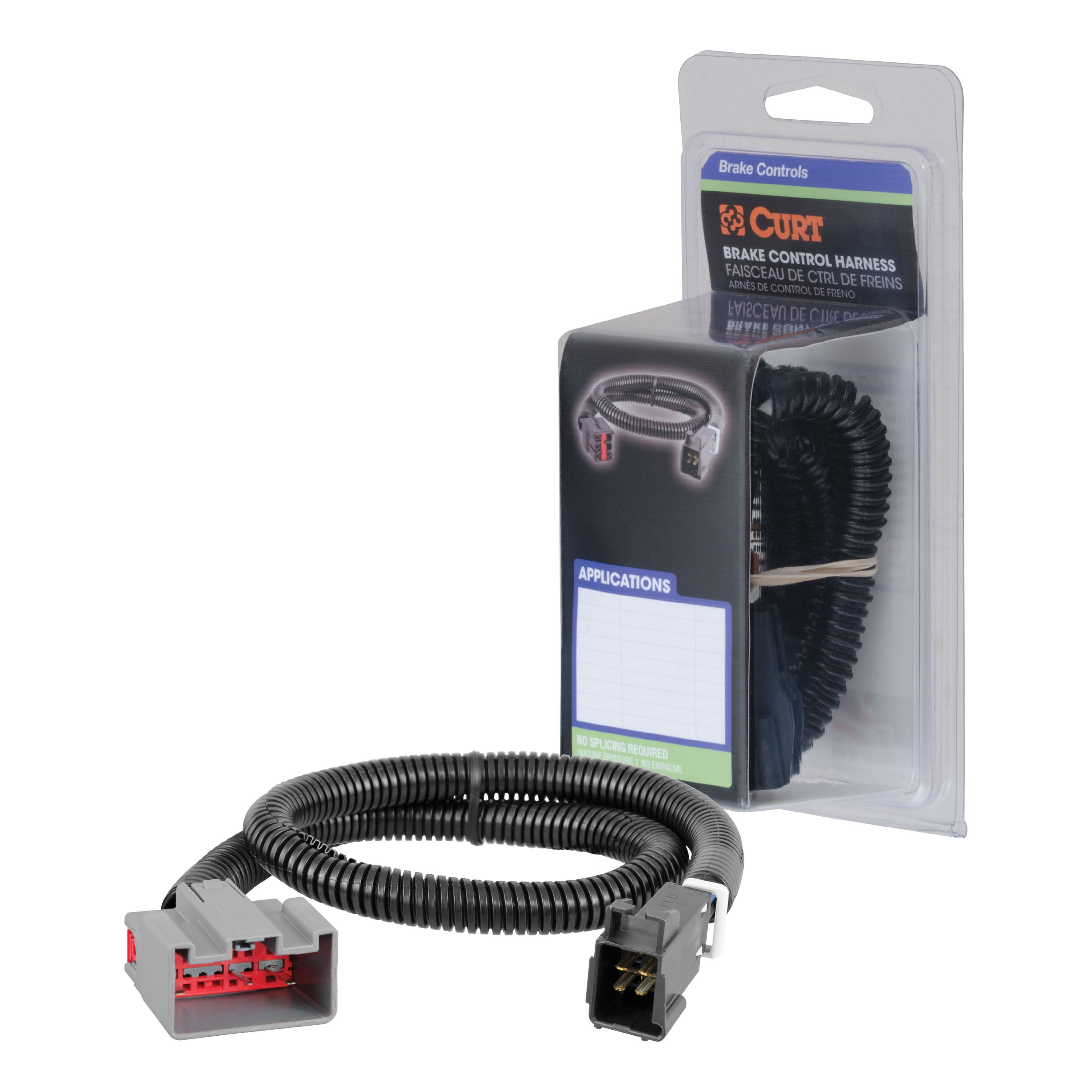
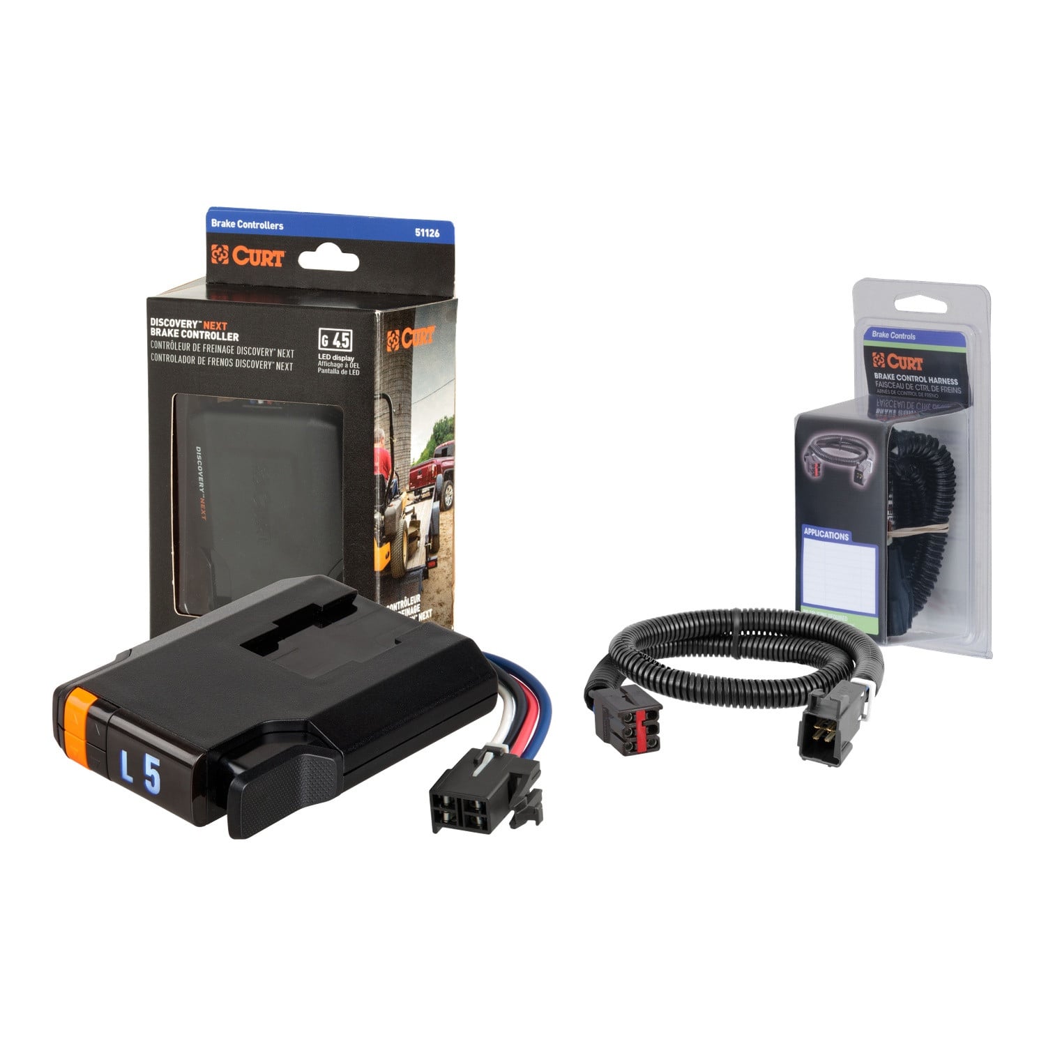
Includes mounting hardware & plug & plan harness
Limited lifetime warranty

Includes mounting hardware & plug & play Harness
Finish: Blank
Installation Difficulty: Novice
Installation Time Exact (Minutes): 20
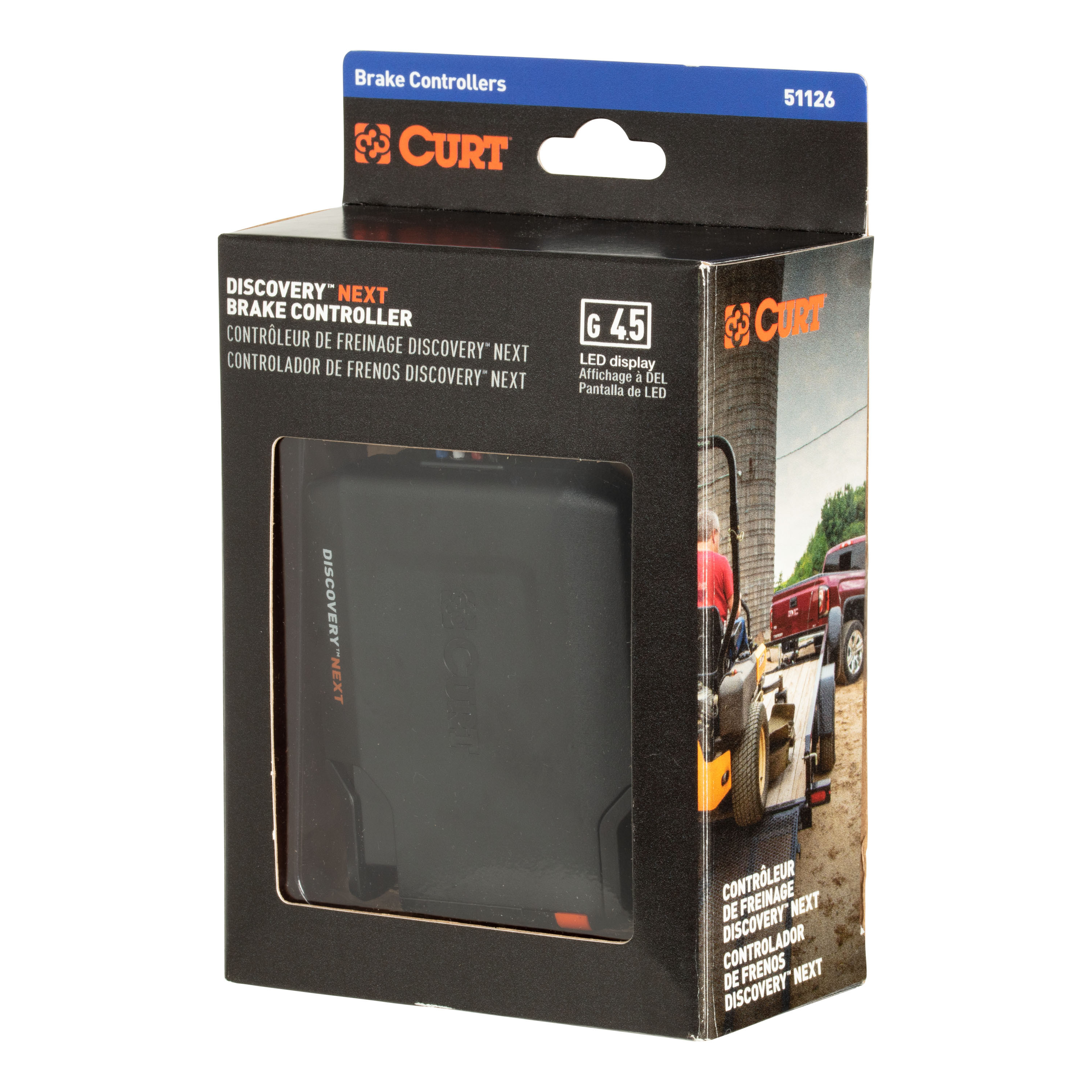
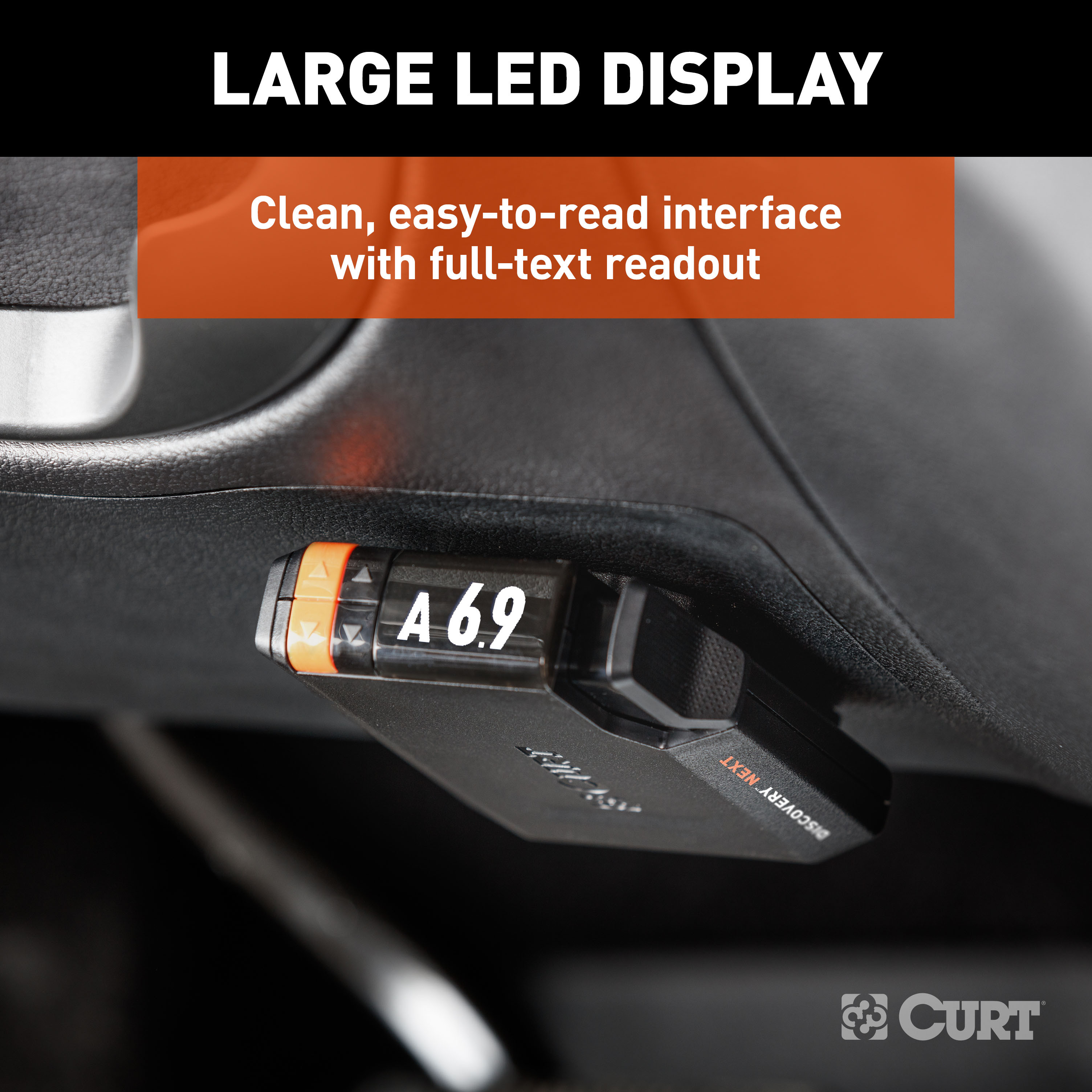
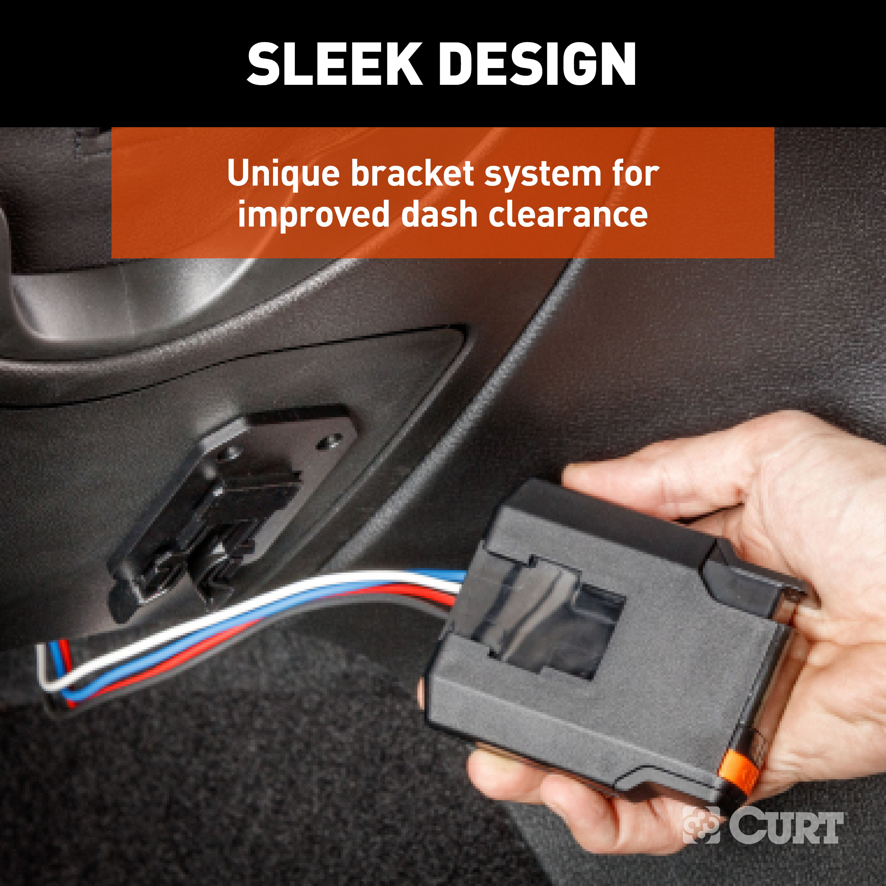
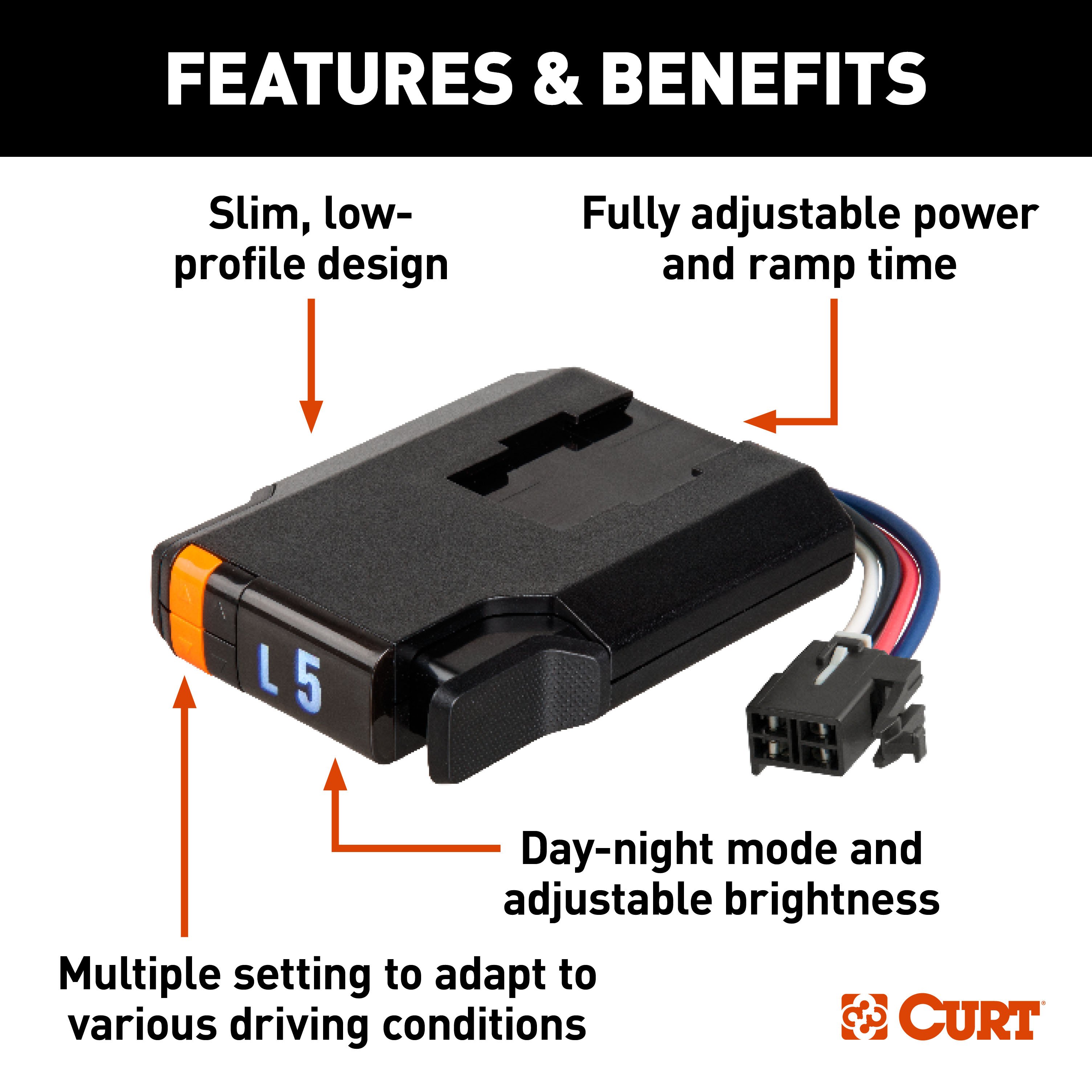
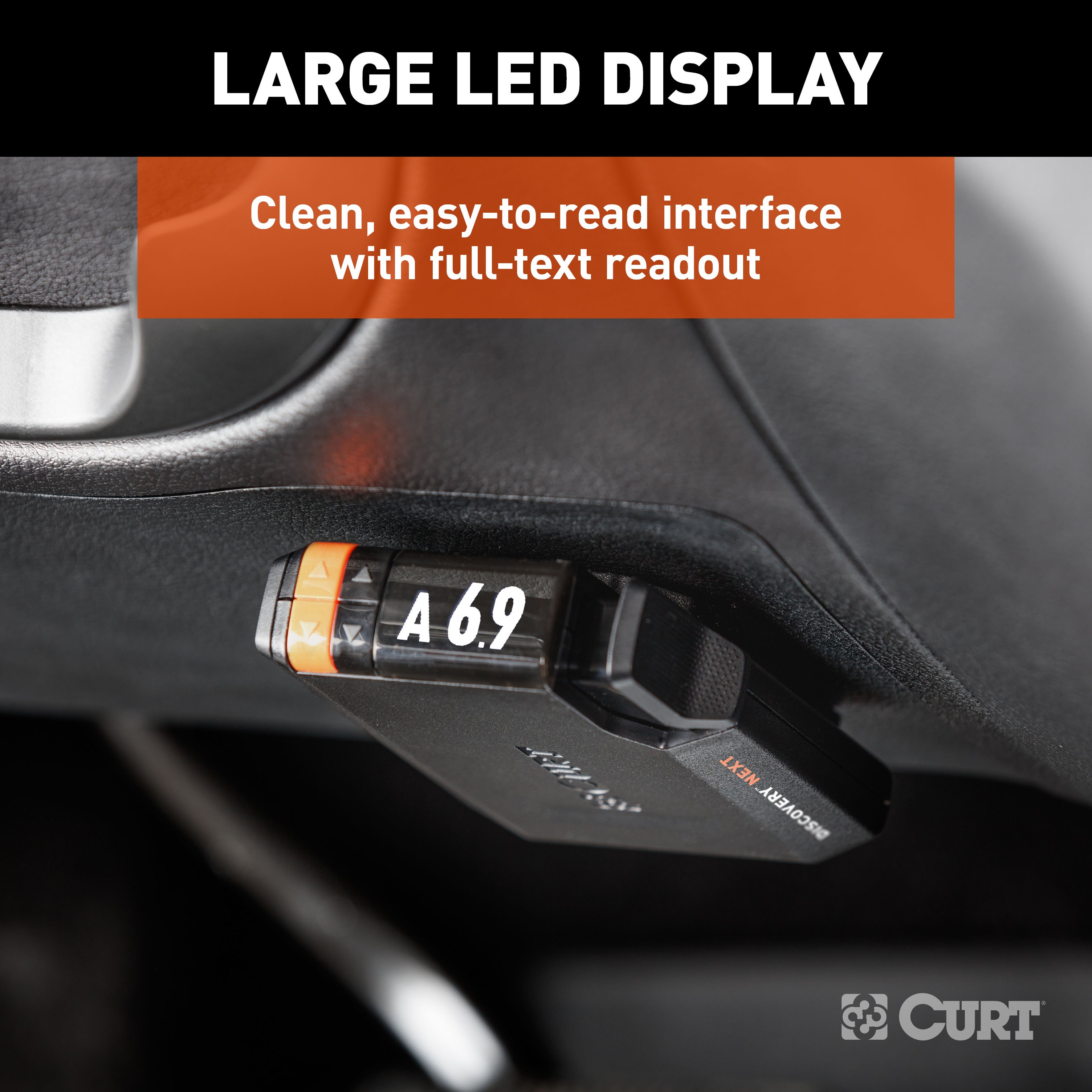
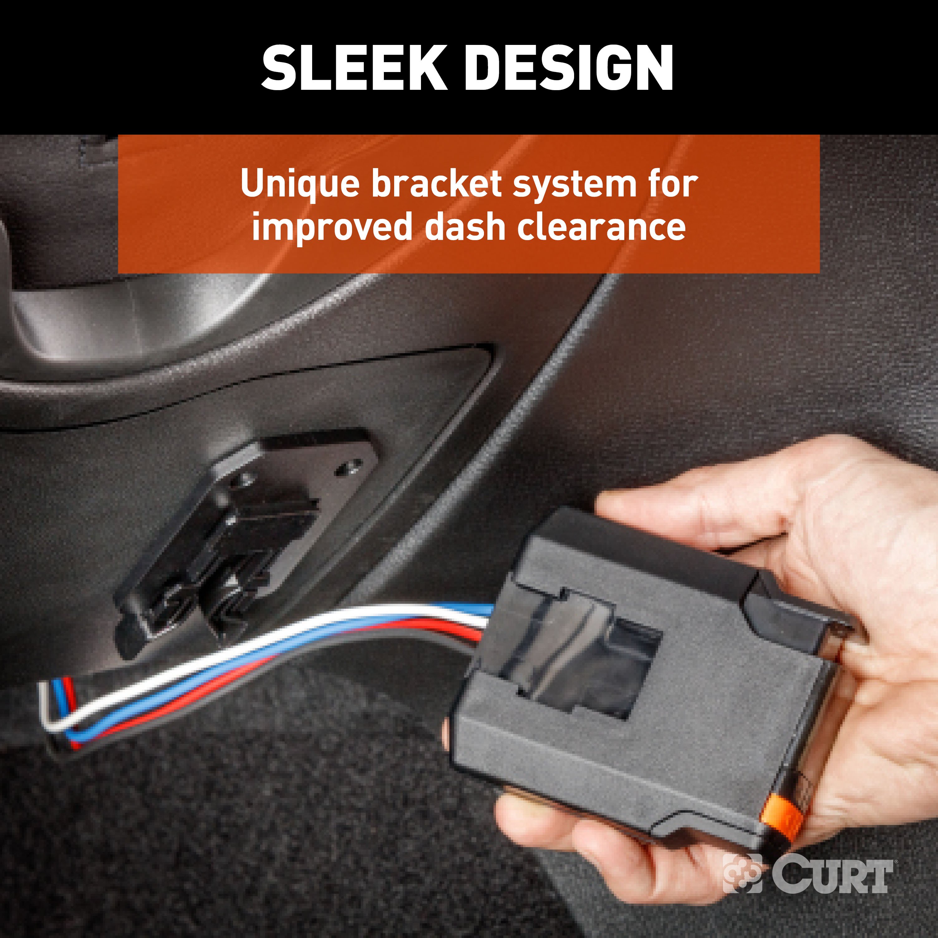
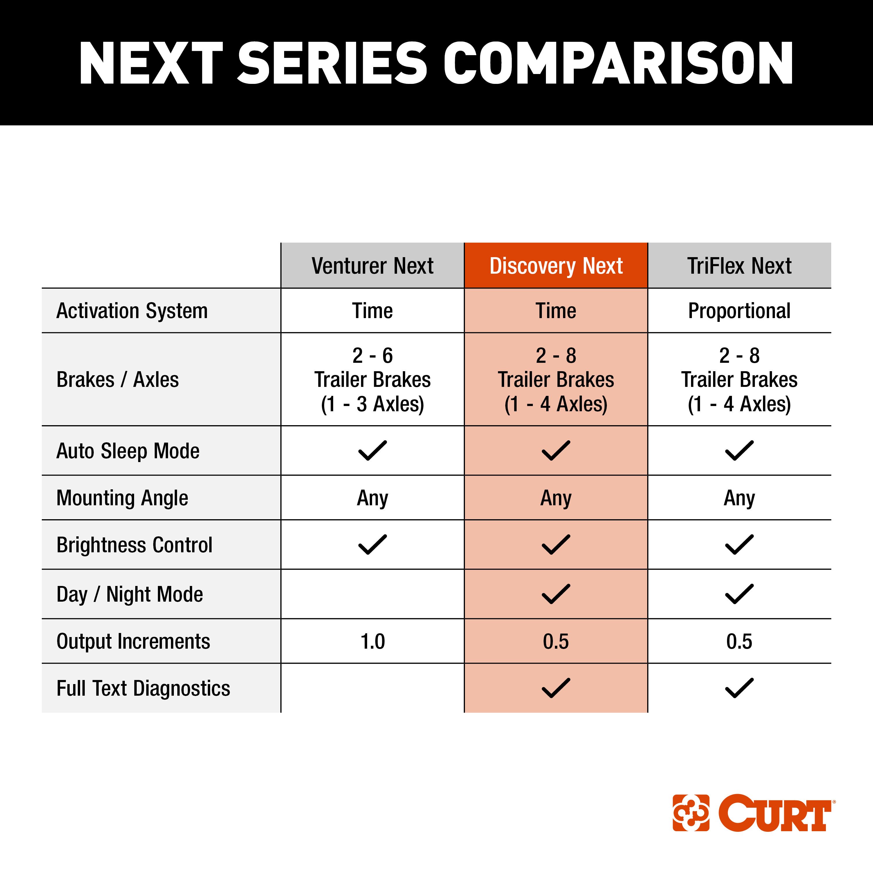
Introducing the CURT Discovery NEXT, a powerful, compact, and user-friendly brake controller designed to ensure reliable operation of your electric trailer brakes right from the comfort of your vehicle's cabin. With its sleek and modern design, as well as a low-profile bracket for improved clearance, this controller delivers exceptional control. Manage the braking system of 2-8 trailers at a time, accommodating 1-4 axles, with ease thanks to its fully adjustable settings that seamlessly adapt to your specific vehicle-trailer configuration. The Discovery NEXT represents an upgraded and enhanced iteration of our highly regarded Discovery brake controller. It boasts compatibility with a wide range of brake systems, including low-volt, PWM, ABS, cruise control, and electric over hydraulic brakes. Its slim profile strikes a balance between functionality and modern aesthetics, ensuring powerful brake control is right at your fingertips without overwhelming your vehicle's dashboard. Stay informed about your brake settings at a glance, courtesy of the LED display that showcases power adjustments in precise 0.5 increments. The display also provides comprehensive full-text diagnostics, simplifying troubleshooting, while the adjustable brightness guarantees optimal visibility for towing during any time of the day or night. Moreover, the included unique mounting bracket further enhances clearance, allowing for an unobtrusive installation. Equipped with a time-delay feature, the Discovery NEXT brake controller offers fully adjustable power and ramp time to achieve precise control. With a selection of 10 gain settings and nine load settings, you can finely calibrate the controller to align perfectly with your specific towing requirements. The ramp-up progress is clearly indicated through LED indicators, and the brightness is adjustable to suit the conditions of daytime or nighttime towing.

CURT offers a variety of high-quality trailer hitches and accessories for select vehicle models. Find the perfect fit for your towing needs at TowUniverse.
CURT, a Lippert brand, offers a complete line of towing products and is the leading manufacturer of custom-fit trailer hitches. We offer the broadest selection of custom-fit hitches, and each one is designed, welded, and coated in Wisconsin.
CURT is also a leader in flat towing products, as well as 5th wheel, gooseneck, and weight distribution hitches, ball mounts, electrical components, cargo solutions, and other towing accessories.
For everything from passenger cars and vans to full-size pickups and SUVs, CURT is 'The First Name in Towing Products®.'

Experts available to answer your questions
Call 888-634-9494One-Year Limited
1 compatible vehicles
| Year | Make & Model | Notes |
|---|---|---|
| 2012 - 2019 | Lincoln MKT | — |
Yes, the 2012-2019 Lincoln MKT CURT Discovery NEXT Time-Delay Trailer Brake Controller for 1-4 Axles #51126 (Part #CURTBC1689) is designed to fit the 2012-2019 Lincoln MKT.
The 2012-2019 Lincoln MKT CURT Discovery NEXT Time-Delay Trailer Brake Controller for 1-4 Axles #51126 (Part #CURTBC1689) fits the following vehicles: 2012-2019 Lincoln MKT. Always verify your specific year, make, and model before ordering.
The 2012-2019 Lincoln MKT CURT Discovery NEXT Time-Delay Trailer Brake Controller for 1-4 Axles #51126 (Part #CURTBC1689) fits 2012-2019 Lincoln MKT models. The 2019 model year is the last year covered by this part number. For newer models, check for an updated version.
The 2012-2019 Lincoln MKT CURT Discovery NEXT Time-Delay Trailer Brake Controller for 1-4 Axles #51126 (Part #CURTBC1689) Refer to the included instructions for installation details. Basic hand tools are typically all you need.
Yes, the CURT 51436/51437 is designed for 2021-Current Ford F-150 models. The installation process varies depending on whether your truck has a factory brake control or a dust cover in the brake control wire housing location on the driver-side kick panel (BH8). If your F-150 has factory controls, you will remove the existing harness and install the CURT custom wiring harness in its place.
Yes, the CURT 51436/51437 is compatible with the 2021 Ford Bronco. For Bronco installation, locate the brake control wire housing on the driver-side compartment under the dash and on the side of the center council, remove the dust cover, and install the brake controller jumper harness in that location.
Yes. If your F-150 does not have a factory brake control, there will be a dust cover in the brake control wire housing location on the driver-side kick panel (BH8). The CURT harness can be installed in this location. However, you will also need to complete the full installation using the brake control instructions and mount the brake control unit as directed in the brake control user manual.
Yes, for 2021-Current Ford F-150 models, you must disconnect the negative battery terminal before beginning installation. Locate the vehicle battery in the engine compartment on the driver side, disconnect the negative terminal, and fasten this wire down and away from the battery while completing the installation process.
You will need: a Phillips screwdriver, a panel trim removal tool, a flathead screwdriver, and a cutting tool. The manual notes that proper tools will improve the quality of installation and reduce the time required.
On 2021-Current Ford F-150 models, the brake control wire housing (BH8) is located on the driver-side kick panel. On 2021 Ford Bronco models, it is located in the driver-side compartment under the dash and on the side of the center council. On some vehicles, the harness may be located in a different location under the dash, above the brake pedal, taped to another harness. If you cannot find it under the dash, check the kick panel location.
Remove tape and protective cover from the connector, taking care not to damage the locking tabs. Insert the connector on the CURT brake control harness into the vehicle connector. Make sure the connector is fully inserted with locking tabs in place. You will hear or feel the connector seat fully when it is properly installed.
Route the brake control harness along the back of the dash and out the bottom to the brake control unit. Insert the brake control harness's black connector into the brake control's quick plug connector. Secure the brake control harness with the provided cable ties, avoiding any pinch points.
Yes, if your vehicle has a center console with a shifter lever, you must remove it to access the vehicle brake control harness connector. The manual provides separate instructions for vehicles with a shifter lever in the center console (Steps 6–7) and vehicles with a center console (Steps 8–12). If your vehicle has a flow-through console, you may skip some steps.
1. Depress the brake and shift the vehicle into first gear. 2. On each side of the console, remove the black plastic floor trim panel. 3. Remove the center console finish plate using a pry tool and gently prying the top out on both sides. 4. Remove the trim panel surrounding the shifter lever. 5. Open the floor console storage compartment cover and remove the three Torx-head screws holding the cover in place. 6. Remove the cover.
1. Remove the two bolts securing the floor console trim in place. 2. Pull up on center console trim to remove, taking care not to damage the alignment tabs. 3. To the left of the radio, locate the skinny panel with the vent and 4×4 selector in it. Gently pull out on the top of the panel and work your way down. 4. On the bottom of the skinny panel, there is a pivot point. Pull the panel out and pivot on this point to allow enough room. 5. Remove the two 7mm bolts securing the pocket in place. 6. Remove the pocket to locate the vehicle brake control harness connector inserted in the back of the pocket. 7. Separate the grey connector from the back of pocket, taking care not to damage the locking tabs.
The floor console storage compartment cover is secured with three Torx-head screws. The floor console trim is secured with two bolts. The pocket in the center console is secured with two 7mm bolts.
After removing the center console components as described in Steps 8–11, the vehicle brake control harness connector will be inserted in the back of the pocket. Remove the two 7mm bolts securing the pocket in place, remove the pocket, and then separate the grey connector from the back of the pocket. Take care not to damage the locking tabs when separating the connector.
After connecting the harness, complete the installation using the brake control instructions. Mount the brake control unit as directed and perform test procedures as instructed in the brake control user manual. Once installed, test for proper function by using a test light or connecting a properly wired trailer.
The manual does not specify a weight or towing capacity rating for this harness. However, the manual warns: do not exceed the product rating or tow vehicle lamp load rating, whichever is lower. Refer to the brake control unit user manual and your vehicle's owner manual for specific capacity information.
Periodic inspection of all wires and connections should be performed to ensure there is no visible damage or loose connections. The manual does not specify an inspection interval, so consult your brake control unit user manual or contact CURT Manufacturing for recommended maintenance intervals.
The manual rates the installation difficulty as 'Easy' based on time and effort involved. However, the actual difficulty may vary depending on the installer's level of expertise, the condition of the vehicle, and whether proper tools and equipment are available. The installation involves removing center console components and working with electrical connectors, so some mechanical aptitude is helpful. If you are not comfortable with this level of work, professional installation is recommended.
The manual confirms that cable ties are provided to secure the brake control harness. The manual does not provide a complete list of all included components. For a full parts list, refer to the product packaging or contact CURT Manufacturing.
Yes, the CURT 51436/51437 is designed for 2021-Current Ford F-150 and 2021 Ford Bronco models. Installation location varies: F-150 uses the driver-side kick panel (BH8), Bronco uses the driver-side compartment under the dash.
Yes, for Ford F-150 models, disconnect the negative battery terminal in the engine compartment before installation and fasten it away from the battery.
Phillips screwdriver, panel trim removal tool, flathead screwdriver, and cutting tool.
Remove protective tape from the connector, insert the CURT harness connector into the vehicle connector until fully seated with locking tabs in place, then route the harness along the back of the dash and secure with provided cable ties, avoiding pinch points.
The manual does not specify a weight rating. Do not exceed the product rating or tow vehicle lamp load rating, whichever is lower. Refer to the brake control unit user manual for capacity details.
Periodically inspect all wires and connections to ensure there is no visible damage or loose connections. The manual does not specify an inspection interval.
The Discovery™ Next Brake Controller (model 51126) is an electronic brake control system that manages trailer brake application based on tow vehicle brake pedal input or manual override. It features an LED display showing output power from 0.5 to 9.9, adjustable gain and load sensitivity controls, manual override capability, and day/night display modes. The controller is time-based, ramping up to full power over time according to gain and load settings.
The 51126 is designed for tow vehicles equipped with a factory brake control plug or compatible with CURT quick plug harnesses. Most trucks and utility vehicles have a factory plug that allows quick brake control installation. Check your vehicle owner's manual for plug availability and location. If your vehicle does not have a factory brake control plug, CURT offers the universal brake control wiring kit #51500. For specific vehicle applications, consult the CURT catalog.
If your vehicle is equipped with a factory brake controller or integrated trailer brake control (ITBC), consult your vehicle owner's manual for any necessary installation instructions. Removal of factory-equipped brake controls may require a dealer to service the harness for it to function properly. Note that removal of the factory quick plug can void the warranty.
You will need: a drill, 1/8" diameter drill bit, Phillips screwdriver, and a pry tool. These tools are used for drilling mounting holes, installing mounting screws, and removing anti-rattle foam from the vehicle plug.
The kit includes: (1) main module with CURT quickplug, (2) mounting bracket, (3) mounting screws, (4) base plate adhesive pad, and (5) cable ties. Depending on your vehicle, you may also need a CURT custom vehicle harness, CURT quick plug with pigtails (#51515 or #51516), or the universal brake control wiring kit (#51500).
The main module and mounting hardware are included, but the wiring harness is not. You will need one of the following: a CURT custom vehicle harness (specific to your vehicle; check CURT catalog for availability), CURT quick plug with pigtails (#51515 or #51516), or the CURT universal brake control wiring kit (#51500) if your vehicle does not have a factory brake control plug.
Yes. Disconnect the tow vehicle's negative battery terminal from its battery post before beginning the installation process. This is a critical safety step to prevent electrical damage and ensure safe wiring.
Locate the vehicle plug and remove any anti-rattle foam. Remove the dust cover before connecting the CURT custom wiring harness. After connecting, route the harness into the dash area, ensuring it is out of the way of any moving parts. Secure the harness with the provided cable ties. Check that your foot controls are not obstructed by the harness.
Use minimum 10-gauge stranded wire for the positive (black) and ground (white) connections to the battery. The blue wire from the trailer plug 'BRAKE' terminal to the brake control must be 10-gauge. All connections to the brake control use 10/12-gauge butt connectors. The red brake input wire is required to activate the brake control. The 30-amp auto-reset circuit breaker must be mounted as close to the battery as possible.
The positive wire (with 30-amp circuit breaker) and ground wires must be connected directly to the tow vehicle's battery using a minimum of 10-gauge stranded wire. Connecting to existing wiring or an alternate ground may damage the vehicle's circuits, lead to failure of the brake control module, loss of trailer brakes, or vehicle fire.
When passing wires through sheet metal, always go through an existing grommet. If there is no grommet, install one or use silicone sealant to protect the wires from sharp edges. This prevents wire damage and potential electrical hazards.
Mount the 30-amp auto-reset circuit breaker as close to the battery as possible. The black wire from the brake control connects to the 'AUX' side of the circuit breaker, which then connects to the battery.
Drilling is optional and depends on your mounting method. If you choose screw installation (in addition to the adhesive pad), you will use a 1/8" diameter drill bit to drill holes through the double-sided adhesive pad to mark the mounting locations on the dash. Adhesive-only mounting does not require drilling.
1. Mount the unit securely to a solid surface easily accessible to the driver, ensuring the area behind the mounting location is clear. 2. Hold the mounting bracket in position and mark hole locations. 3. Peel off one release liner of the double-sided adhesive pad and stick it onto the brake controller mount. 4. (Optional) If using screws, drill 1/8" holes through the adhesive pad to see marked locations. 5. Remove the second release liner and firmly press the mount to the dash. 6. (Optional) Install and tighten screws with a Phillips screwdriver, being careful not to over-tighten. 7. Slide the controller onto the mount until it locks into place; you will hear a clicking noise when correctly installed.
No. The angle at which the controller is mounted will not affect the operation or calibration of the controller.
Once all electrical connections are complete inside the vehicle, plug the trailer electrical connector into the tow vehicle plug. The brake controller will sense the trailer upon connecting after 10-15 seconds. Upon connecting and applying the brakes, the brake controller will sense the trailer immediately. Every time the vehicle starts, the controller will restart, displaying the start-up icon. Once the display becomes blank/black, it will remain blank/black until the manual control is applied, the orange adjustment rocker switches are pressed, or the vehicle brake pedal is applied.
Make preliminary gain and load adjustments with the trailer connected and engine running to ensure proper charge voltage. Adjust the output/gain by pressing the orange rocker switches to the left of the display to the desired range. Adjust the controller's brake load by pressing the right rocker switch until the brake control is in the desired range.
Disconnect the electrical plug between the trailer and tow vehicle before testing a breakaway switch. Failure to disconnect may damage the brake control unit.
Avoid mounting the brake control module near a CB radio or other RF (radio frequency) transmitter, as this can interfere with the controller's operation.
Connect the module to the quick plug to provide accessible wires. Connect the white ground wire of the main module and the ground wire of a standard 1156 automotive bulb in a socket to the negative terminal of a charged 12V battery. Leave the red brake input wire and blue output wire disconnected. Connect the black battery wire of the module to the positive terminal of the 12V battery. If wired properly and operational, the display will power on. You can use CURT #51515/#51516 quick plug with pigtails or push pins to make direct connections to the female terminals. Ensure all wires, push pins and test leads do not contact each other or any metal surface to avoid damage.
Adjust the output setting to its maximum setting of 10 and the sensitivity settings to its most aggressive setting of 9. Ensure the blue trailer brake signal wire is connected to the bulb. Once the start-up screen disappears or turns black, the control module is ready. Activate the manual control up to its full output. While actuating the manual control, the brightness of the bulb will correspond with the output shown by the brake control. The display will ramp up according to the pressure applied to the manual control lever, and the light will turn on in accordance with the amount of pressure applied. Release the manual control to deactivate and turn off the light.
To recalibrate the brake controller, restart the vehicle or disconnect the controller from the vehicle. The brake controller will retain the last settings applied upon restarting.
Yes. The gain and load controls can be adjusted anytime when trailer load changes and adjustment is needed for changing road or driving conditions. This process should be repeated for any weather, weight or loading changes to the items in/on the vehicle or trailer.
Check for no power to controller, no ground, reversed black and white wires, or a blown circuit breaker. Review the 'Wiring' section of the manual and check and repair all connections. Verify that the negative battery terminal is properly connected, the positive and ground wires are connected directly to the battery with minimum 10-gauge stranded wire, and the 30-amp circuit breaker is functioning.
This indicates the red wire is connected to the wrong side of the stoplight switch or to an incorrect wire. Check and repair the brake control wiring connections according to the 'Wiring' section of the manual. The red wire must be connected to the correct terminal of the stoplight switch to properly signal brake application.
This indicates the tow vehicle's system voltage is low. The brake controller is not receiving enough voltage to provide the trailer with the needed voltage at the settings the controller is at. Check the tow vehicle's battery and charging system. Service may be needed to restore proper charging voltage.
This indicates the red wire is connected to the ground side of the stoplight switch or is shorted to ground. Check the brake control wiring and repair the connection. The issue may require a change to the switch setting. Refer to the 'Manual Control' section of the manual for proper wiring configuration.
This indicates a short in the blue wire output circuit or trailer plug. Locate and correct the short in the wiring or connector. Inspect the blue wire for damage, pinching, or contact with metal surfaces, and check the trailer plug connections for proper fit and blockages.
This indicates inadequate battery or ground wiring to the brake controller. Check the brake controller wiring, particularly the black (battery positive) and white (ground) wires. Ensure they are connected directly to the battery with minimum 10-gauge stranded wire and that all connections are secure.
This indicates no connection between the brake controller and trailer brakes in the blue wire circuit. Confirm the connection to the trailer is properly made. Confirm connector terminal positions are correct. Check the trailer for proper brake wiring and connections. Verify the blue wire from the tow vehicle's trailer plug 'BRAKE' terminal is properly connected to the brake control's blue wire using a 10/12-gauge butt connector.
The trailer may be miswired, the wiring may be shorted, or a bulb may be burnt out. Check all bulbs for proper function. Check for possible shorts in the wiring, particularly the red brake signal wire and blue output wire. Inspect connections for proper fit and blockages.
This indicates a short to the trailer brakes in the wiring or brake assembly. Stop immediately and check for shorts in the wiring and in each electric brake. Do not operate the trailer until the short is located and corrected. Inspect all connections and wiring for damage, pinching, or contact with metal surfaces.
An electrical connection may have failed. Stop and check the trailer connector for proper fit and blockages. Ensure the connector is fully seated and that no debris or corrosion is preventing a good connection. Clean and reseat the connector if necessary.
This indicates a loss of trailer connection, unplugged connector, or bad wiring. Stop and check the trailer connector to ensure it is properly plugged in. Inspect the wiring for damage, pinching, or corrosion. Repair or replace damaged wiring as needed.
The 51126 fits tow vehicles with a factory brake control plug or compatible with CURT quick plug harnesses. Check your vehicle owner's manual for plug availability. If your vehicle lacks a factory plug, use CURT universal kit #51500. Consult the CURT catalog for specific vehicle applications.
You need a CURT custom vehicle harness (check CURT catalog), CURT quick plug with pigtails (#51515 or #51516), or universal kit #51500 if your vehicle lacks a factory brake control plug. A drill, 1/8" bit, Phillips screwdriver, and pry tool are required.
Use minimum 10-gauge stranded wire for positive (black) and ground (white) connections to the battery. The blue trailer brake wire must be 10-gauge. All connections to the brake control use 10/12-gauge butt connectors. Mount the 30-amp auto-reset circuit breaker as close to the battery as possible.
Drilling is optional. If you choose screw installation in addition to the adhesive pad, use a 1/8" drill bit to mark mounting locations. Adhesive-only mounting does not require drilling.
Yes. Disconnect the negative battery terminal before beginning installation to prevent electrical damage and ensure safe wiring.
Positive and ground wires must connect directly to the battery using minimum 10-gauge stranded wire. Connecting to existing wiring or alternate ground may damage vehicle circuits, cause brake failure, loss of trailer brakes, or vehicle fire. Do not mount near CB radios or RF transmitters.
Perform a bench test using a 12V battery and 1156 bulb to verify the display powers on and manual control activates the bulb. Then conduct a test drive on a dry, level surface at approximately 25 mph, adjusting gain and load until stops are firm without trailer tire lock-up.
Yes. Adjust gain and load settings anytime trailer load, weather, or driving conditions change. This ensures smooth, firm stops without trailer tire lock-up.
Cause: No power to controller, no ground, reversed black and white wires, or blown circuit breaker. Solution: Check and repair all connections per the 'Wiring' section. Verify negative battery terminal is connected, positive and ground wires connect directly to battery with minimum 10-gauge stranded wire, and the 30-amp circuit breaker is functioning.
Cause: Red wire connected to wrong side of stoplight switch or incorrect wire. Solution: Check and repair brake control wiring per the 'Wiring' section. Red wire must connect to correct stoplight switch terminal to signal brake application.
Cause: Tow vehicle system voltage is low. Solution: Check tow vehicle battery and charging system. The brake controller is not receiving enough voltage to provide the trailer with needed voltage at current settings. Service may be required to restore proper charging voltage.
Cause: Red wire connected to ground side of stoplight switch or shorted to ground. Solution: Check brake control wiring and repair connection. May require change to switch setting per the 'Manual Control' section.
Cause: Short in blue wire output circuit or trailer plug. Solution: Locate and correct the short. Inspect blue wire for damage, pinching, or metal contact. Check trailer plug connections for proper fit and blockages.
Cause: Inadequate battery or ground wiring to brake controller. Solution: Check brake controller wiring, particularly black (battery positive) and white (ground) wires. Ensure they connect directly to battery with minimum 10-gauge stranded wire and all connections are secure.
Cause: No connection between brake controller and trailer brakes in blue wire circuit. Solution: Confirm trailer connection is properly made and connector terminal positions are correct. Check trailer brake wiring. Verify blue wire from tow vehicle trailer plug 'BRAKE' terminal connects to brake control blue wire with 10/12-gauge butt connector.
Cause: Miswired trailer, shorted wiring, or burnt-out bulb. Solution: Check all bulbs for proper function. Check for shorts in wiring, particularly red brake signal and blue output wires. Inspect connections for proper fit and blockages.
Cause: Short to trailer brakes in wiring or brake assembly. Solution: Stop immediately and check for shorts in wiring and each electric brake. Do not operate trailer until short is located and corrected. Inspect all connections and wiring for damage, pinching, or metal contact.
Cause: Electrical connection failed. Solution: Stop and check trailer connector for proper fit and blockages. Ensure connector is fully seated. Clean and reseat connector if necessary to restore good connection.
Cause: Loss of trailer connection, unplugged connector, or bad wiring. Solution: Stop and check trailer connector is properly plugged in. Inspect wiring for damage, pinching, or corrosion. Repair or replace damaged wiring as needed.
On Sale Today
Original price was $155.90. Current price is $146.59.You save $9.31 (6%)
Free Shipping
Ships free on all orders
 Authorized Dealer

Quick Ship
In stock and ready to ship — order now!
FREE ShippingFREE SHIPPING
Estimated delivery Fri, Oct 9 - Mon, Oct 12
Order before 2 PM EST Monday–Friday for same-day processing
Guaranteed safe & secure checkout
No reviews have been added for this product.