B&W 16K Continuum Weight Distribution Kit - 2" Shank 2-5/16" Ball, 600-1600 Lbs. Tongue Weight For Standard Trailer CouplersB&W Trailer Hitches$1,299.00Out of Stock
View productOur in-house experts typically reply within one business day.

B&W Trailer Hitches


Always the correct part
We know our products
Quality Products
Free Shipping!
Always the correct part
We know our products
Quality Products
Free Shipping!


B&W Trailer Hitches is an American manufacturer known for durable, innovative towing products, including gooseneck hitches, fifth-wheel hitches, receiver hitches, and ball mounts. Built in Kansas by employee-owners, B&W products are engineered for dependable performance, easy installation, and long-lasting quality.
B&W Trailer Hitches is an American manufacturer known for building innovative, dependable towing products designed to make hitching easier and towing more comfortable. The company began in 1987 in Humboldt, Kansas, when founders Roger Baker and Joe Works combined their fabrication experience to build custom truck beds and solve common problems faced by truck owners.
B&W changed the gooseneck hitch industry with the introduction of the Turnoverball Gooseneck Hitch. Its under-bed mounting system and reversible hitch ball allowed truck owners to quickly store the ball beneath the bed, leaving a clean and unobstructed surface when the hitch was not in use. B&W later applied the same practical approach to the Companion Fifth Wheel Hitch, creating a removable fifth-wheel hitch engineered for a quiet, smooth, and secure towing experience.
Today, B&W manufactures gooseneck hitches, fifth-wheel hitches, receiver hitches, ball mounts, and towing accessories at its nearly 600,000-square-foot facility. The company is owned by approximately 500 employee-owners who remain committed to American manufacturing, trusted materials, skilled craftsmanship, and long-lasting product quality.
Whether you are towing a work trailer, livestock trailer, camper, or fifth wheel, B&W Trailer Hitches offers thoughtfully engineered towing equipment built to perform mile after mile.
Experts available to answer your questions
Call 888-634-9494The Continuum fits most vehicles and trailers, but three measurements must be verified. First, your tow vehicle receiver must be at least 2" wide (reducers may be used for larger receivers, but may reduce tow ratings). Second, measure the distance from the top of your trailer coupler to the ground (Measurement A) and from the top inside edge of your vehicle receiver to the ground (Measurement B). Use the formula A + 2 – B. If the result is between –1-1/8" and 9-3/8" for the standard head unit (or –4" to 12-3/8" for the extended pin block head unit), fitment is compatible. Third, your trailer must have an A-frame coupler design with rails approximately 2" wide and 5–6" tall, with 6–9" distance between rails behind the coupler.
Required tools: ratchet with 9/16" socket, torque wrench, tape measure, marker, grease gun and grease (Multi-Purpose Lithium Complex Grease - NGLI Grade 2), eye protection, and vent hose cutting tool. If installing kit WDHL4511, also need 1-1/8" socket and box end wrench.
The manual does not require battery disconnection. However, if the trailer jack foot is wider than 6", it must be removed during installation. The jack is used during setup to raise the trailer tongue so the load bar assembly can be attached, then lowered before towing.
The manual does not mention drilling as a required installation step. However, non-structural trailer frame parts may require modification or removal if they obstruct the hydraulic cylinder, such as sections of propane tank trays. Use appropriate protective gear and tools for any modifications.
3/8" bolts and nuts: 40 ft.-lbs. 3/8" nuts on fork holder bracket: 30 ft.-lbs. 3/4" bolt on cylinder extension: 150 ft.-lbs. Load bar assembly 1/2" × 4-1/4" bolts: 125 ft.-lbs. Load bar assembly 1/2" × 2" bolts: 80 ft.-lbs. Ball nut: 475 ft.-lbs. (requires professional tools and help).
Before each tow: visually inspect the hitch, load bars, vehicle receiver, trailer coupler, and frame for cracks, deformation, or damage; check all pins are present and clipped; verify all bolts are tight; inspect the hydraulic system for leaks; examine abrasion-prone areas for excessive wear; and ensure the jack foot is raised above the load bars and clear of the area between them. Chock trailer tires before coupling or uncoupling.
Grease the head unit before each trip and every 250–500 miles of towing using the two grease fittings with Multi-Purpose Lithium Complex Grease - NGLI Grade 2. Rotate the spindle 90° toward the passenger side and add grease to the top fitting, then rotate 180° toward the driver side and add grease to the bottom fitting until a small bead purges from the area between the head unit and spindle. Periodically spray white lithium grease on the load bar latching mechanism, pump handle, and hydraulic cylinder swivel ball end.
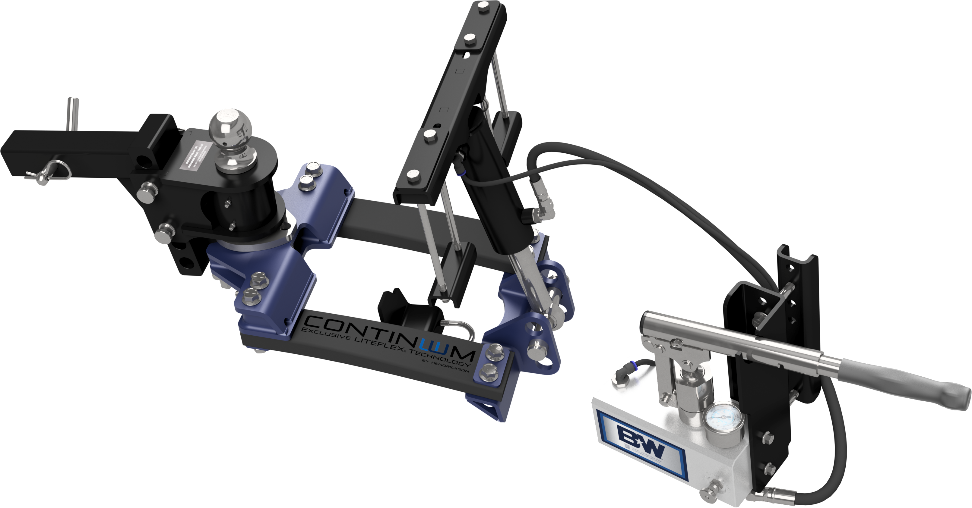
The Continuum is designed to transfer part of a coupled trailer's weight from the tow vehicle's rear tires to its front tires using a hydraulic cylinder. The amount of weight transferred is adjustable and expressed as Front Axle Load Restoration (FALR), a percentage of the trailer load on the rear tires that is restored to the front. B&W recommends an FALR between 50% and 100%.
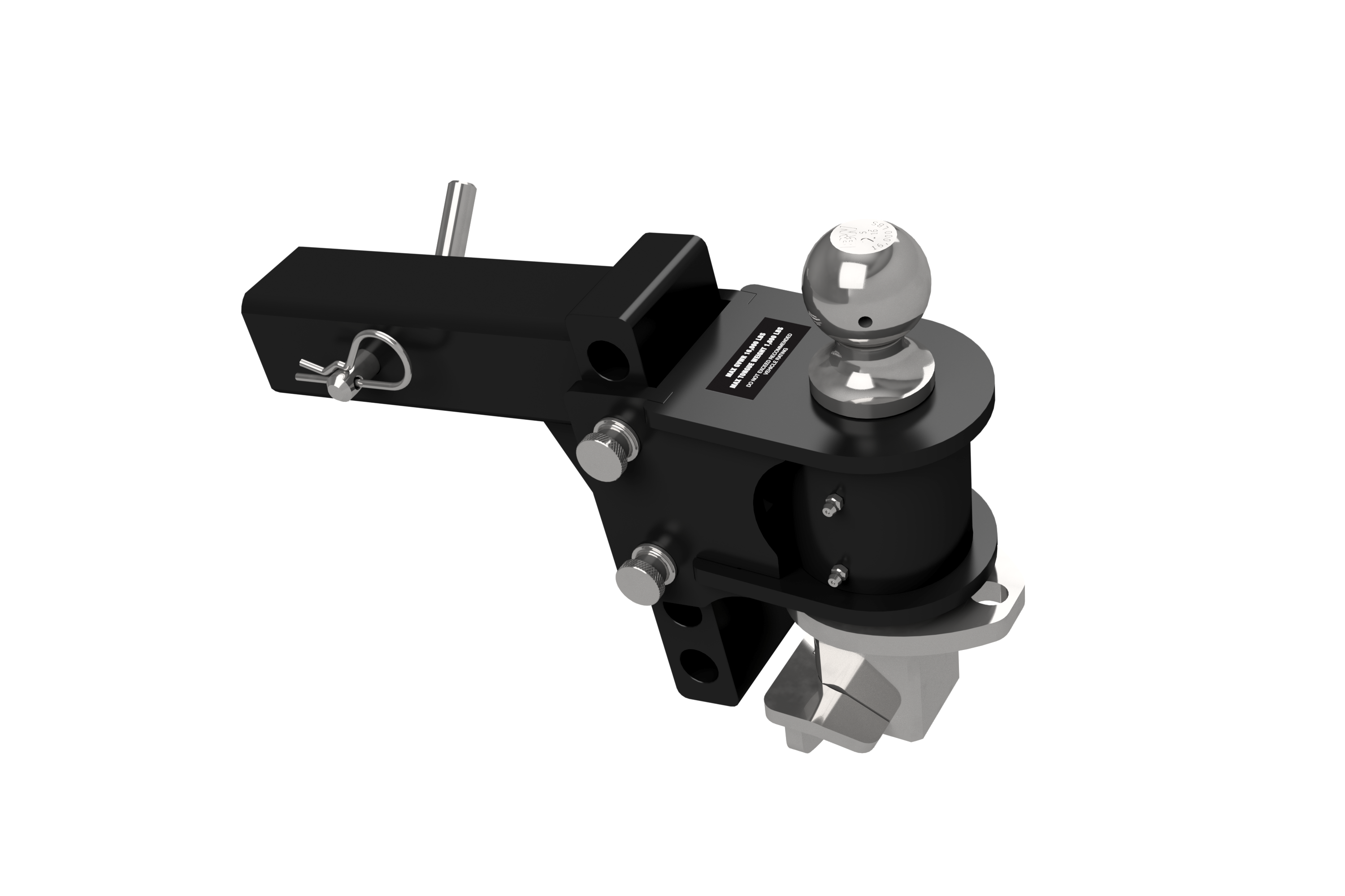
Box WDHH45XX contains the head unit (standard 2" shown) and one 5/8" receiver pin with cotter. Box WDHL45XX contains the hydraulic pump and cylinder, load bar assembly, top cylinder mount, pump mount bracket, pump mount inside clamp, two frame clamps, two top mount washer plates, fork holder bracket, fork holder clamp, top cylinder mount pin, and cotter pin. Bolt bag 4510-200 contains 2 carriage bolts (3/8" × 2-1/2"), 4 cap screws (3/8" × 8"), 3 flange head bolts (3/8" × 3/4"), 2 flange head bolts (3/8" × 3"), and 8 flange nuts (3/8"). Kit WDHL4511 includes an extension kit with hydraulic cylinder extension, 3/4" × 4-1/4" cap screw, and 3/4" lock nut.
The Continuum hitch is rated for trailers with a maximum weight of 16,000 lbs and is capable of supporting tongue weights between 600 lbs and 1,600 lbs.
Yes, the Continuum hitch is compatible with surge brake trailers. However, the majority of surge brake trailers include a central member in the tongue that prevents the hitch from being installed, so compatibility must be verified on a case-by-case basis.
Yes, the Continuum hitch can be used with a tow vehicle that has an auto leveling system, but the auto leveling system must be turned off before coupling the trailer to the tow vehicle and must remain off during setup and while using the Continuum hitch.
The standard head unit provides a total adjustment range of 10-1/2", from a lowest setting of 1-1/8" to a highest setting of 9-3/8". The holes in the pin blocks are 1-1/2" apart, and the pin block can be turned over if needed to access additional positions.
The extended pin block head unit provides a total adjustment range of 16-3/8", from a lowest setting of 4" to a highest setting of 12-3/8".
The Continuum hitch is configured for trailers with 2-5/16" ball couplers. A 2" ball replacement is available for purchase from B&W (part number HB94021). B&W recommends having a dealership replace the ball because changing it requires specialized tools and torquing the nut to 475 ft.-lbs.
The choice depends on the distance between the top of your trailer frame rails and the top of the coupler. Use kit WDHL4510 if the top of the coupler is above the trailer frame or less than 2.5" below the top of the trailer frame. Use kit WDHL4511 if the top of the coupler is more than 2.5" below the top of the trailer frame. Kit WDHL4511 includes a hydraulic cylinder extension.
The A-frame rails must be approximately 2" wide and 5–6" tall. Frame rails that are shorter (4" minimum) or taller (7" maximum) are supported but require alternate bolts available upon request from B&W. The area behind the coupler and between the frame rails must be open with at least 2" of open space in front of the next object (such as a propane tank tray). The distance between the frame rails must be between 6" and 9" at the mounting location behind the coupler.
The extended shank is a 4" longer option designed for users unable to open their tailgate while using the Continuum hitch. B&W typically recommends using the standard shank if possible, as moving the hitch ball further from the rear axle may adversely affect trailering dynamics in some cases. However, for many setups the difference is negligible, and every truck and trailer combination is different.
Both the trailer and tow vehicle must be on a flat, level area. Chock trailer tires when working around the trailer. Level the trailer by measuring the distance between the trailer frame and the ground at the front and rear, then adjust until these measurements are equal. The truck and trailer must be fully loaded during hitch installation and setup, just as they would be when towing.
Measure the distance from the ground to the top of the trailer ball coupler. Place the head unit into the receiver of the tow vehicle and measure how high the ball is above the ground. The ball should be set 1–2" higher than the coupler measurement. Remove the head unit and adjust the pins to set the ball height correctly. The holes in the pin blocks are 1-1/2" apart. If required, the pin block can be turned over to access additional positions.
If present, mark the front and back edges of the propane tank cover, then remove it. Remove the propane tanks and set them aside to allow clearance for installing the hitch. You may need to remove the propane tank tray; if there is at least 2" of space between the tray and the rear edge of the coupler, it may not need to be removed. Before removing the tray, mark its edges on the trailer frame so it can be reinstalled in the same location. These marks will be referenced when mounting the pump.
It may be necessary to relocate the trailer's break-away cable, propane lines, and wiring harness. During installation, move or re-route any wires, cables, or hoses that could be damaged or pinched by the addition of the hitch.
Place the head unit into the receiver of the tow vehicle at the correct pin position (determined by measuring coupler and ball heights). Using the hole in the receiver, pin the head unit to the tow vehicle and secure with a 5/8" cotter pin. Secure the pins in the pin block with lynch pins. The lynch pin spring must close on the same side as the bump on the top of the pin.
If installing kit WDHL4511, bolt the hydraulic cylinder extension to the cross tube of the hydraulic cylinder using a 3/4" × 4-1/4" cap screw and 3/4" lock nut. Torque the nut to 150 ft.-lbs. If installing kit WDHL4510, skip this step as no extension is needed.
Carefully lift the hydraulic cylinder. Move it up under the trailer A-frame so the hydraulic hose passes under the driver side frame rail. With the cross tube end of the cylinder up, pass the cylinder between the two rails of the A-frame. Pin the cylinder to the top cylinder mount and secure with the provided cotter pin. Rest the top cylinder mount on the frame.
Locate the pump mount bracket, inside clamp, two 3/8" × 3" bolts, and two 3/8" flange nuts. Depending on the height of your trailer frame, identify which hole to use for mounting (see Figure C3). Place the pump mount bracket and inside clamp next to the driver side frame and attach using the 3/8" bolts and nuts. Leave the nuts loose at this stage.
Using Figure A7 on page 4, locate a clear span of the driver side frame to secure the hydraulic pump. If the trailer had a propane tank cover, the installation area should be roughly 4" behind the mark made on the frame. Relocate any obstacles or cables in the area. When the best location has been determined, adjust the pump mount bracket so it is level with the frame. Tighten the two 3/8" nuts holding the pump mount inside clamp by alternating between each nut so that when tight, the inside clamp and pump mount bracket are flat against the frame rails. Torque the 3/8" nuts to 40 ft.-lbs.
Retrieve the hydraulic pump and cylinder. Carefully lay the hydraulic cylinder below the A-frame temporarily. Retrieve the three 3/8" × 3/4" flange bolts. Attach the hydraulic pump to the pump mount bracket using the bolts. Torque the 3/8" bolts to 40 ft.-lbs. If the pump handle interferes with trailer parts after installation, the pump will need to be moved by removing it and loosening the pump mount bracket bolts to adjust the pump location, then reinstalling.
Do not tamper or attempt to adjust the pressure relief valve on the bottom of the hydraulic pump. It is set at the factory to a safe level. Adjusting the pressure relief valve could result in serious injury or death.
Retrieve the top mount washer plates, frame clamps, 3/8" × 8" cap screws, and four 3/8" flange nuts. Place the top mount washer plates over the top cylinder mount slots. Place a 3/8" × 8" cap screw in each of the holes in the washer plates—two screws will be on the inside of the A-frame and two on the outside. Depending on the height of the frame rails, place the frame clamps over the 3/8" cap screws. Use the 3/8" flange nuts to attach the frame clamps, but do not fully tighten the nuts at this stage.
Push the top cylinder mount as far back as possible. Use a tape measure to check that the top cylinder mount is square with the trailer and centered left to right. Tighten the four 3/8" nuts holding the frame clamps by alternating between each nut so that when tight, the frame clamps are flat against the bottom of the frame rails. Torque the 3/8" nuts to 40 ft.-lbs.
If the propane tank tray was removed for installation, use the marks made on the frame to reinstall the tray in the same location.
If the cylinder is extended more than 1/2" from the cylinder barrel, retract the cylinder by closing the needle valve and pumping the handle. Pump just enough to retract the cylinder close to the barrel. The pressure gauge should still read zero.
Pull the vent hose up between the frame and the hydraulic pump unit. Push in on the blue fitting to remove the plug from the air hose fitting on the top of the hydraulic pump. Cut the vent hose to length and insert the cut end into the air fitting and press in firmly. A small amount of pressure may be released when the plug is pulled out; this is normal.
Rotate the spindle 90° toward the passenger side and add grease into the top grease Zerk fitting. Rotate the spindle 180° toward the driver side and add grease to the bottom grease Zerk fitting. Add grease to the bottom Zerk until a small bead of grease purges from the area between the head unit and the spindle. Spin the spindle all the way around a couple of times after greasing. Use Multi-Purpose Lithium Complex Grease - NGLI Grade 2.
Align and lower the trailer coupler onto the ball. The tow vehicle and the trailer need to be on the same level surface.
Retrieve the load bar assembly. Remove the pin and bushings from the lower cylinder mount. Raise the trailer jack high enough that the load bar assembly can slide under it. Pin the hydraulic cylinder to the center hole in the lower cylinder mount using the removed pin and bushings.
Fully open the needle valve on the hydraulic pump. Push down on the lower cylinder mount to extend the hydraulic cylinder until it is fully extended with about 5" of chrome rod showing. Lift the load bar assembly and slide it into the bottom of the spindle of the head unit until the latch pin of the fork engages with the spindle. If the fork does not slide into the spindle far enough to engage the latch pin, use the upper hole in the lower cylinder mount instead.
The fork holder bracket installation is optional. The fork holder is designed to provide a resting place for the front portion of the load bar assembly when the trailer is not hooked to a tow vehicle. If the trailer needs to be moved by a vehicle not equipped with the head assembly, the jack can be raised while the load bar assembly rests on the bracket until the load bar assembly is constrained underneath the bottom of the trailer frame. The fork holder bracket will only fit on trailer tongue jacks with a 2" diameter or smaller leg. Safety chains may be used to hold the load bar assembly if the fork holder cannot be installed.
Retrieve the fork holder bracket, fork holder clamp, two 3/8" carriage bolts, and two 3/8" nuts. Insert the two carriage bolts into the fork holder bracket, then place the assembly around the leg of the jack stand. Attach the fork holder clamp to the fork holder bracket using the 3/8" carriage bolts, then secure it with the two 3/8" nuts. The bracket must be aligned so it is in front of the tongue jack and above the jack foot. Torque the 3/8" nuts to 30 ft.-lbs.
Attach any wiring, break-away cables, and safety chains to the tow vehicle. If your chains are long enough, they may be passed down through the load bar assembly and attached to the tow vehicle. No part of the chain should be tight against the load bar assembly.
In some cases, in order to attach or detach the load bars, the trailer tongue jack may need to be used to raise the trailer tongue.
The 3/4" lock nut on the hydraulic cylinder extension should be torqued to 150 ft.-lbs.
3/8" bolts and nuts should be torqued to 40 ft.-lbs., except for the 3/8" nuts on the fork holder bracket, which should be torqued to 30 ft.-lbs.
The 1-1/4" nut on the ball must be torqued to 475 ft.-lbs. This requires specialized tools (1-7/8" deep well socket) and B&W recommends having a dealership replace the ball. Failure to correctly torque the nut could lead to serious injury or death.
The load bar assembly bolts were factory-tightened and are not expected to come loose. If they do, torque the 1/2" × 4-1/4" bolts to 125 ft.-lbs. and the 1/2" × 2" bolts to 80 ft.-lbs. Tighten from the head of the bolt only.
The manual does not describe any electrical connections for the Continuum hitch. The hydraulic system is mechanical and does not require wiring. However, trailer wiring, break-away cables, and safety chains must be attached to the tow vehicle as part of the installation.
Adding hitch components to the chassis of any vehicle or trailer can be hazardous. There is potential for unexpected combustion of fuel, electric shock, burns, shifting or falling of unstable vehicle, damage to vehicle, injury from tool usage, and many other hazards. This installation must be completed by someone who is aware of the hazards involved and is knowledgeable of proper safety procedures for vehicle and trailer modification and usage of the equipment required. Without proper knowledge, towing can be a dangerous activity. Understand all the risks involved with towing before proceeding.
While installation is being performed, check for signs of damage or excessive corrosion. Do not install hitch components over vehicle or trailer parts that are broken or have compromised structural integrity.
Do not exceed the tow or tongue rating of the coupler, tow or tongue rating of the hitch, or tow or weight ratings of the tow vehicle or trailer. See vehicle and trailer manufacturer information for ratings. Exceeding these ratings may cause damage to towing components or loss of attachment between the trailer and vehicle.
No. Do not modify this product in any manner. Doing so could alter its integrity and lead to a loss of attachment between the trailer and the tow vehicle.
Tire condition can influence trailer sway. Never tow with tires that are under inflated, overloaded, or damaged. These conditions will greatly lower the speed at which the trailer will remain stable and may lead to loss of control. Check tire condition before each tow.
The needle valve is used to hold and remove pressure from the hydraulic cylinder and should only be operated by hand. Never use tools to tighten or loosen the valve. Using excessive force in either direction on the needle valve will damage the pump unit.
Before towing, raise the jack foot above the load bars. If the jack foot or any stationary accessories are not clear of the area between the load bars, remove them before towing. Large objects between the load bars may strike the bars during tight turns. Flexible objects like safety chains may pass between the bars while towing.
If sway occurs, slow down and drive at a lower speed. Towing stability is how fast the trailer can be towed before it becomes unstable and sway can occur. The more stable the setup is, the higher the speed the trailer can be towed. Factors that can adversely affect towing stability include towing speed, road and weather conditions, trailer load distribution and tongue weight, and tire conditions and load rating.
Perform an inspection of the tow setup. Double check that the trailer's connections to the tow vehicle are all secured. Chock trailer tires before attempting to couple or uncouple the tow vehicle.
The Continuum hitch is designed to transfer part of a coupled trailer's weight from the tow vehicle's rear tires to its front tires. Each towing configuration will require a different amount of pressure. The industry term for how much weight is moved to the front tires is Front Axle Load Restoration (FALR), expressed as a percentage of the trailer load on the rear tires which is restored to the front. Refer to your vehicle's user manual on how to properly set up and adjust a weight distribution hitch. If the vehicle manufacturer does not provide this information, use either a tongue weight scale or the wheel well method. B&W recommends an FALR between 50% and 100%.
Before coupling, measure the distance from the ground to the top edge of the front wheel well (measurement A). Couple the trailer and tow vehicle, attach the load bar assembly to the head unit, then lift the jack foot off the ground. Measure the distance from the ground to the top edge of the front wheel well (measurement B). To restore wheel well height to represent a specific FALR percentage, use the formula: B – ((B – A) × FALR/100) = Target measurement C. Close the needle valve, pull the pump handle out and extend it, then pump the handle to restore load from the rear tires to the front tires until the wheel well height reaches the target measurement. Return the handle to the holder. If moving the handle increased the pressure, use the needle valve to reduce the pressure back to the reading taken when the wheel well height was correct.
If available, use a tongue weight scale to measure the tongue weight of your trailer. Use the provided chart on page 10 to find the correct cylinder load (PSI) based on your tongue weight and desired FALR percentage. Close the needle valve, pull the pump handle out and extend it, then pump the handle to pressurize the cylinder to the target PSI shown on the pressure indicator.
If the target measurement cannot be reached before the cylinder rod is fully retracted and the cylinder bottoms out, then the cylinder will need to be secured to the lower hole in the lower cylinder mount instead of the center hole.
Open the needle valve on the hydraulic pump. Allow the cylinder to extend until the load bar assembly can be removed from the head unit. It may be necessary to push down on the lower cylinder mount to aid the lowering of the cylinder. Retract the latch pin by pulling up on the latch pin release lever. Pull the load bar assembly out of the head unit. Place the load bar onto the fork holder bracket.
Write down the reading on the pressure indicator for future reference. A log is provided on page 13 to keep track of the pressure.
Before each trip and every 250–500 miles of towing: grease the head unit using the two grease fittings with Multi-Purpose Lithium Complex Grease - NGLI Grade 2; check the hitch, load bars, vehicle receiver, trailer coupler, and trailer frame for physical damage, including metal deformation, fractures in welds, bent pins, and damage in heavy-load areas; examine abrasion-prone regions for excessive wear or gouging; inspect the hydraulic system for leaks in the hose, pump, and cylinder; check that all pins are present and clipped; and check that all bolts are tight and no components are loose.
Periodically as needed: spray white lithium grease onto the latching mechanism of the load bar assembly and the top of the fork; spray white lithium grease onto the hydraulic pump handle; spray white lithium grease onto the swivel ball end of the hydraulic cylinder; and lubricate and clean the pins and pin holes in the pin block.
Replacement balls must be sourced from B&W. The 2-5/16" replacement ball part number is HB94050, and the 2" replacement ball part number is HB94021. To replace the ball: remove the head unit from the tow vehicle; separate the ball mount and pin block by removing the two pins; loosen the set screw until the spindle can be removed from the socket (1/4" Allen wrench); remove the grease from the spindle and from inside the ball mount; remove the 1-1/4" nut and washer from the ball (1-7/8" deep well socket); replace the ball in the ball mount and secure with the provided washer and nut; torque the nut to 475 ft.-lbs.; insert the clean spindle back into the ball mount; tighten the set screw until it bottoms out and test that the spindle cannot be pulled out; and apply grease to the spindle and ball mount using the two grease fittings. B&W recommends having a dealership replace the ball because changing it requires specialized tools and very high torque.
You may see up to a 10% pressure loss within a few minutes of first loading the spring bars. This is normal and due to the closed looped hydraulic system settling in.
During towing and parking, the hydraulic pressure will vary as the tow vehicle and trailer turn and pass over surfaces with varying heights. This is normal. Do not adjust the cylinder pressure when the truck and trailer are turned or on surfaces with varying heights. Before making any adjustments to the hydraulic cylinder pressure, move to a smooth flat surface and align the tow vehicle and trailer in a straight line with one another.
The hydraulic system is designed to automatically relieve hydraulic pressure when the system pressure exceeds 3,000 psi. This feature is to prevent damage to the hitch, tow vehicle, and trailer during discrete/overload events.
Friction sway control is built-in to the hitch and can lessen sway as much as the current leading brands. However, sway control is much less important to towing stability than other considerations, such as speed, road and weather conditions, trailer load distribution, tire conditions, and many other factors.
Yes, the Continuum hitch has a single point of attachment which gives it a large turning clearance.
The distance between the top of the trailer frame and the top of the coupler ball determines which Continuum kit you need. If the coupler is above the frame or less than 2.5" below the top of the frame, use kit WDHL4510. If the coupler is more than 2.5" below the top of the frame, use kit WDHL4511.
If the pump handle interferes with parts of the trailer after installation is complete, the pump will need to be moved. Remove the pump and loosen the pump mount bracket bolts to adjust the pump location. Follow the installation steps to reinstall the pump at a new location.
If the fork does not slide into the spindle far enough to engage the latch pin, use the upper hole in the lower cylinder mount instead of the center hole. This will adjust the height of the load bar assembly relative to the spindle.
If the target measurement cannot be reached before the cylinder rod is fully retracted and the cylinder bottoms out, then the cylinder will need to be secured to the lower hole in the lower cylinder mount instead of the center hole. This will change the mechanical advantage and allow the system to reach the target measurement.
If moving the handle to the holder increased the pressure shown on the pressure indicator, use the needle valve to reduce the pressure back to the reading taken when the wheel well height was correct.
You may see up to a 10% pressure loss within a few minutes of first loading the spring bars. This is normal and due to the closed looped hydraulic system settling in. If pressure loss exceeds 10% or continues beyond a few minutes, inspect the hydraulic system for leaks in the hose, pump, and cylinder.
If sway occurs, slow down and drive at a lower speed. Towing stability is how fast the trailer can be towed before it becomes unstable and sway can occur. The more stable the setup is, the higher the speed the trailer can be towed. Factors that can adversely affect towing stability include towing speed, road and weather conditions, trailer load distribution and tongue weight, and tire conditions and load rating. Ensure tires are properly inflated and not overloaded or damaged.
In some cases, in order to attach or detach the load bars, the trailer tongue jack may need to be used to raise the trailer tongue. This will change the angle of the load bar assembly relative to the spindle and allow it to slide in or out more easily.
The load bar assembly bolts were factory-tightened and are not expected to come loose. If they do, torque the 1/2" × 4-1/4" bolts to 125 ft.-lbs. and the 1/2" × 2" bolts to 80 ft.-lbs. Tighten from the head of the bolt only. For support, contact B&W Trailer Hitches Customer Service.
Free Shipping
Ships free on all orders
 Authorized Dealer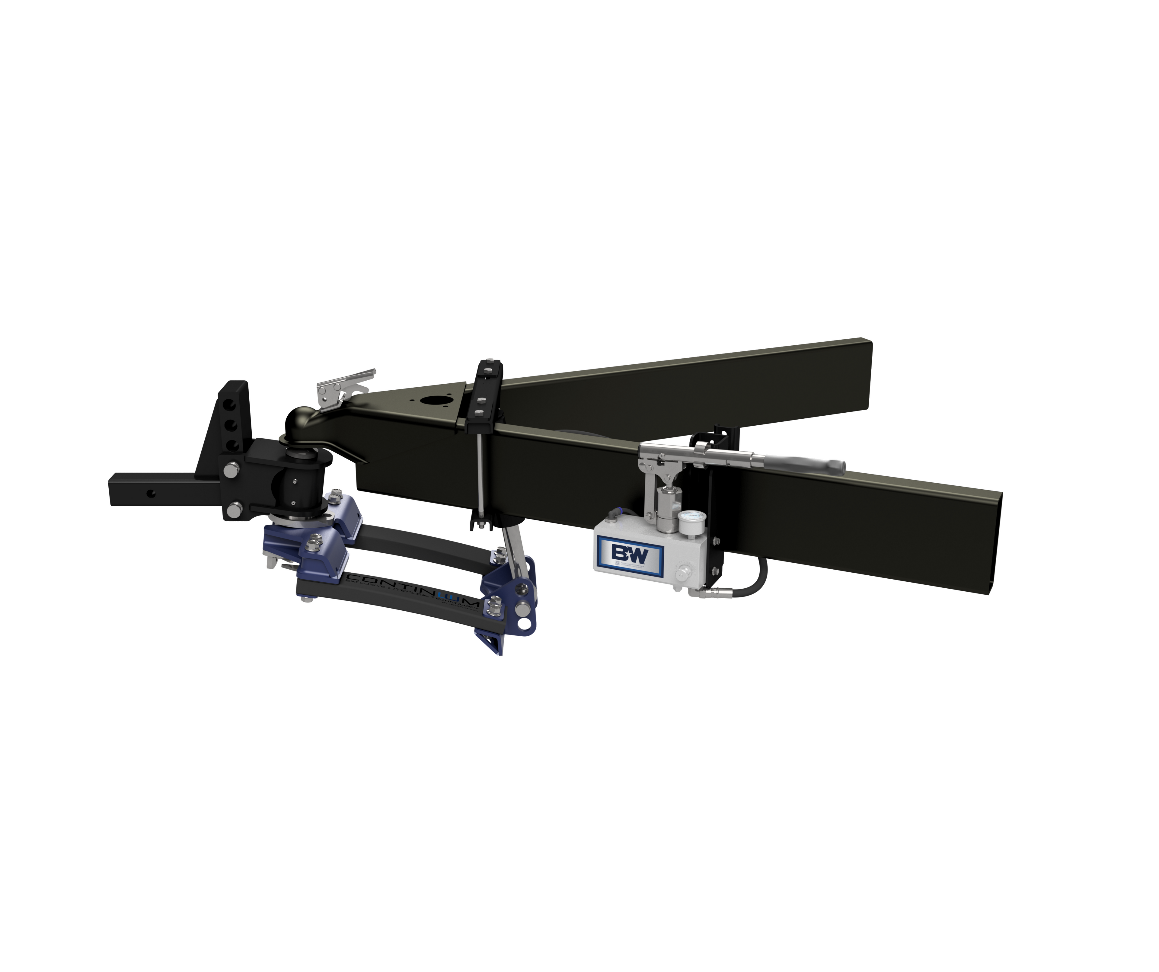


Quick Ship
In stock and ready to ship — order now!
FREE ShippingFREE SHIPPING
Estimated delivery Sun, Sep 27 - Wed, Sep 30
Order before 2 PM EST Monday–Friday for same-day processing
Guaranteed safe & secure checkout
No reviews have been added for this product.