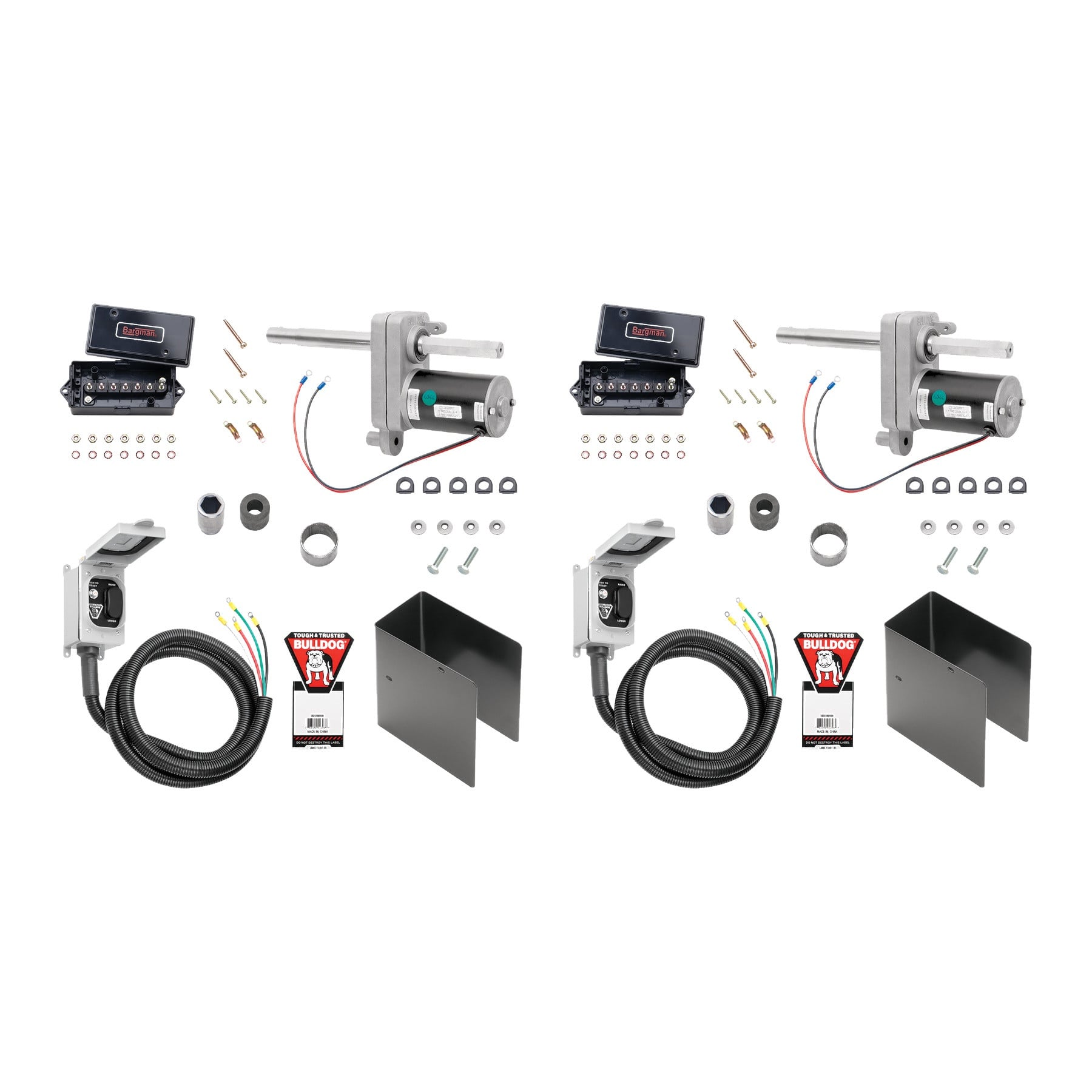
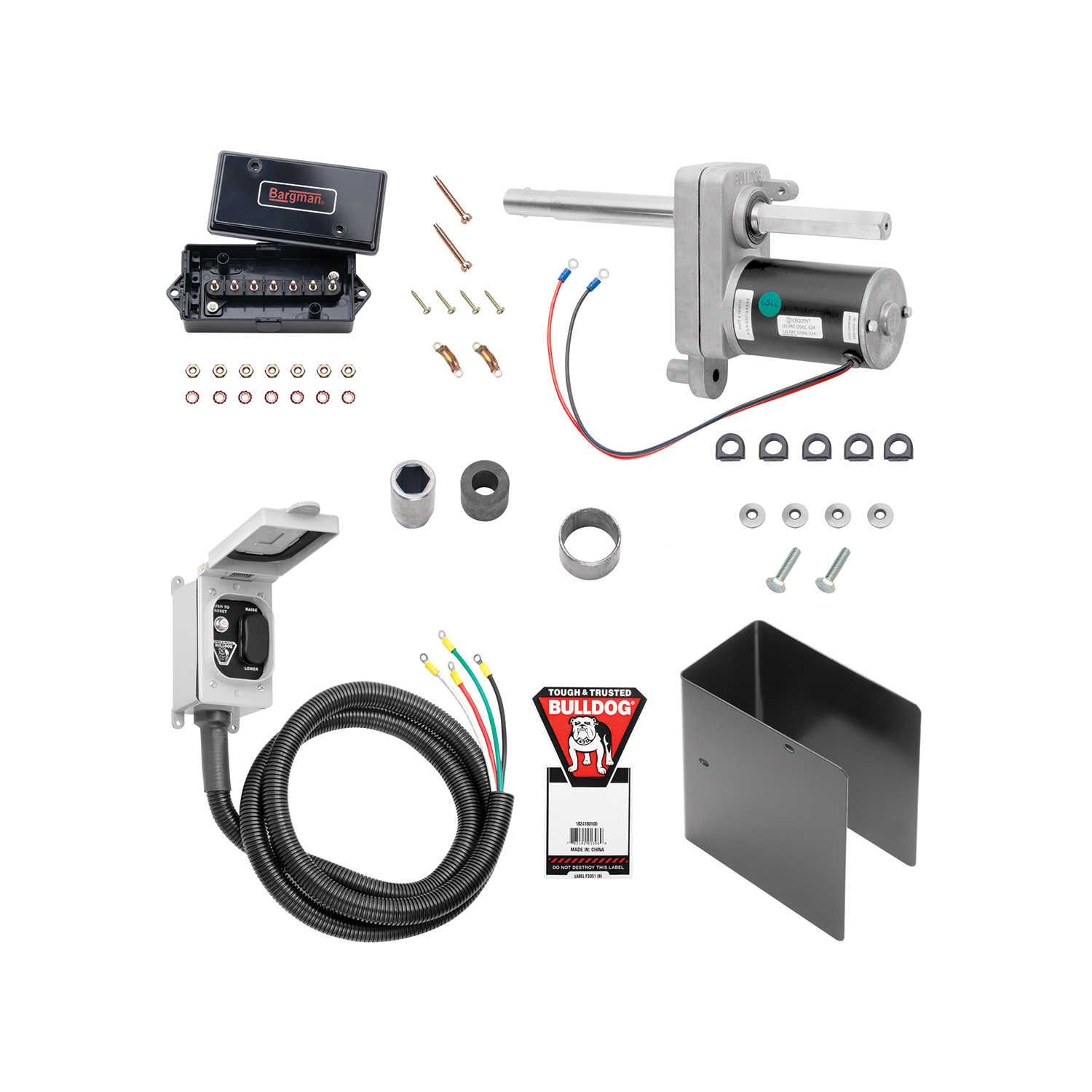
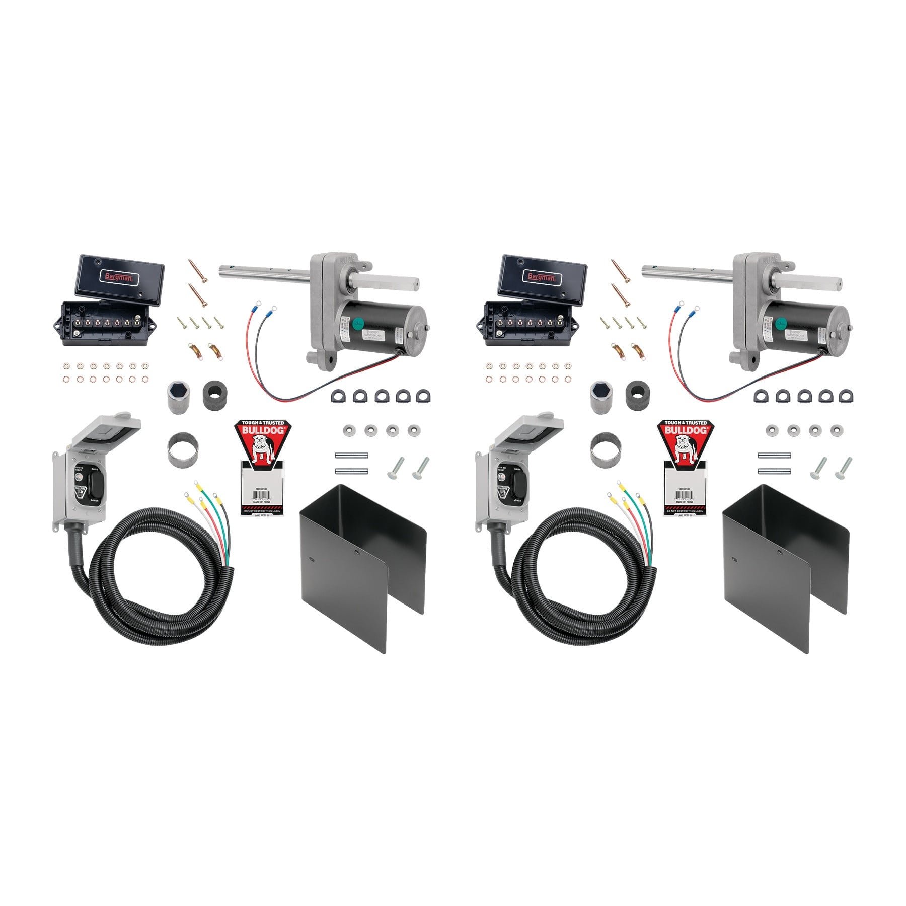
BULLDOG (2-Pack) Electric Powered Kit - Bulldog 2 speed Planetary only - 12K 2-SpeedBulldogOriginal price was $2,345.00. Current price is $2,034.80.Out of Stock
View productOur in-house experts typically reply within one business day.

Bulldog


Always the correct part
We know our products
Quality Products
Free Shipping!
Always the correct part
We know our products
Quality Products
Free Shipping!
Complete kit bundle containing all necessary components for your project. Professional-grade components designed for reliable performance and long-lasting durability.

| BRAND: | BULLDOG |
| PART NUMBER: | 1824180100 |
| WARRANTY: | LIMITED 5 YEAR WARRANTY |
| WEIGHT: | 19.75 LBS |
| CAPACITY: | 12,000 LBS. |
| COLOR: | BLACK |
| ATTACHED WHEELS: | NO |
| MATERIAL: | STEEL |
| HANDLE STYLE: | SIDEWIND |
| SPEEDY LIFT: | NO |
Keywords: BD1824180100-20PK bundle kit, complete kit, professional components, industrial kit, BD1824180100, BULLDOG

Founded in 1920, Bulldog has become the standard for heavy-duty trailer connection hardware in agricultural, military and utility service. The line covers gooseneck hitches and couplers, A-frame and channel-mount trailer couplers with the Wedge-Latch mechanism, and heavy-duty jacks, built for unmatched strength, reliability and safety under demanding loads.
Bulldog was founded in 1920 and has spent more than a century supplying the connection hardware that heavy trailers depend on. Its market has always been the demanding end: agricultural, military and utility applications where a coupler failure is not an inconvenience but a serious incident. The brand summarises its position as Tough and Tested, and it sits within the Horizon Global towing group alongside Reese, Draw-Tite, Fulton, Tekonsha, Bargman and Wesbar.
Gooseneck equipment is the brand's signature. Gooseneck hitches mount in the truck bed over the rear axle, which places the load where the chassis can carry it properly and allows far tighter turning than a receiver hitch permits. Matching gooseneck couplers attach at the trailer end, in round tube and square configurations across the capacity range used by livestock, equipment and flatbed trailers.
The conventional trailer coupler range is built around the Wedge-Latch mechanism, which uses a wedge to take up wear between coupler and ball rather than relying on a fixed clamp that loosens over time. That matters on a trailer accumulating hard miles, where slack in the coupling shows up as noise and shock loading. Couplers are offered in A-frame form for standard tongues and in channel-mount form for straight tongue and fabricated frames, with adjustable channel versions that let a coupler be positioned to suit the tongue height.
Heavy-duty jacks complete the line, sized for the tongue weights that gooseneck and equipment trailers generate. Across the range the emphasis is consistent: forged and heavy-section components, load ratings backed by testing, and hardware specified for agricultural, military and heavy-duty commercial use rather than occasional recreational towing.
Experts available to answer your questions
Call 888-634-94945 Years
The Powered Drive is an electric motor-driven unit that replaces the manual cross shaft on Bulldog Jacks, allowing you to raise and lower the jack using a rocker switch instead of hand-cranking. It is designed for single-speed and two-speed planetary Bulldog Jacks, including tandem jack systems. The unit is sealed and maintenance-free.
The Powered Drive is designed for Bulldog Jacks, including single-speed and two-speed planetary models. If your jack has non-welded hex bushings, refer to Service Bulletin F3310 (included). If you are installing on a two-speed planetary jack, refer to Service Bulletin F3376 (included). These bulletins provide specific instructions for your jack type. Contact Cequent Performance Products at 1-800-632-3290 or www.cequentgroup.com if you are uncertain about compatibility.
Yes. For tandem jack systems, the powered drive should be installed between the two jacks on the 'street-side' jack. You will need to use the included hex coupling, which can be welded to a length of 1 inch Schedule 40 pipe. The pipe is then connected to the second jack's cross shaft with a ⅜" x 2" long bolt and lock nut, Grade 5 (not included), torqued to 18 ft. lbs. Make sure both jacks are in the same position relative to the ground before final connection.
Yes. You must disconnect the battery ground cable before installation to avoid accidental shock and/or damage to the electrical system. Reconnect the battery ground cable only after all wiring is complete and you are ready to test the operation of the powered drive.
Yes. All welding must be performed by an AWS (American Welding Society) certified welder. This includes welding the torque stop tube to the jack outer tube and, if you are using tandem jacks, welding the hex coupling to the 1 inch Schedule 40 pipe.
The first step is to remove the jack cross shaft. If your jack has non-welded hex bushings, refer to Service Bulletin F3310 (included). If you are installing on a two-speed planetary jack, refer to Service Bulletin F3376 (included). Both bulletins provide detailed instructions for removing the cross shaft.
Install the powered drive/shaft so that the powered drive is on the non-geared side of the jack with the motor down and within the profile of the jack. For tandem jack systems, the powered drive should be between the two jacks and installed on the 'street-side' jack.
For two-speed tandem installations, the grease zerks (lubrication points) on the jack will no longer be easily accessible. You have the option to drill two ¼" holes on an accessible side of the jack outer tube and install new grease zerks (not included) to maintain access for lubrication.
The torque stop tube is a component that prevents the motor from rotating. With the powered drive/shaft temporarily installed, use it to locate the torque stop tube on the jack outer tube wall. Place the torque stop tube on the rubber bumper (with the powered drive/shaft installed) and mark the location on the outer tube. Remove the powered drive/shaft and weld the torque stop tube to the jack outer tube at the marked location. When reassembling, make sure to place the energy-absorbing rubber bumper into the torque stop tube.
Use the standard hole for normal installation. Do not use hole #2 (see Figure 2 in the manual).
Torque the ¼" x 1" bolts to 6 ft. lbs. The bolts should be sandwiched between two ¼" rubber bonded washers on each bolt, with the rubber side against the cover. You have the option to apply thread lock or retaining compound (not included) to the bolts.
The included hardware consists of: ¼" x 1" bolts, ¼" rubber bonded washers, a hex coupling (for tandem installations), non-split tubing or loom (for protecting electrical leads), and a Bulldog decal for the cover. Additional items not included but required for tandem installation are: 1 inch Schedule 40 pipe, a ⅜" x 2" long bolt and lock nut (Grade 5), and new grease zerks if you choose to drill access holes on two-speed tandem installations.
According to the wiring diagram (Figure 5), the electrical system uses the following wire colors: Red (+) and Black (-) for the motor leads, Red and Black for the battery leads, and Green and White for the wiring harness pigtails. All leads connect to a terminal box with six junction box terminal studs.
Enclose the powered drive leads and wiring harness leads in a section of non-split tubing or loom (included) to protect them from damage.
Attach the terminal box to the trailer at a location that will allow for connection of the powered drive leads to the terminal box studs. See the wiring diagram (Figure 5) for reference.
Locate and attach the switch box of the wiring harness at a desired location on the trailer. Note that mounting hardware is not included, so you will need to provide your own fasteners.
Yes. After reconnecting the battery ground and testing the operation of the powered drive, apply sealant (not included) to all terminal box entrances to protect the electrical connections from moisture and corrosion.
Never position any part of your body under any portion of the product or the load being supported. Fully retract and/or rotate the jack before towing. When using the drop leg, make certain the drop leg pin is fully inserted before using the jack. Do not allow children to play on or around the product or the load being supported. Secure the load, vehicle and trailer from rolling (by blocking wheels) when operating the jack or coupling the trailer. Never exceed the maximum rated capacity of the jack. Keep clear of pinch points at the drop leg pin and holes in the drop leg, as the drop leg will naturally drop or retract very quickly depending on the model.
The jack capacity is limited to the lesser of the jack, footplate, or caster wheel capacity. Never exceed the maximum rated capacity. Refer to the stamped markings or decals on the product to obtain the rated capacity. If uncertain, contact Cequent Performance Products at 1-800-632-3290 or www.cequentgroup.com.
No. These jacks are designed for vertical loading only. Excessive side forces may cause jack failure and must be avoided.
No. Never attempt to adjust the drop leg when the jack is under load. Always adjust the drop leg only when the jack is not supporting any weight.
After all wiring is complete, reconnect the battery ground cable and test the operation of the powered drive to ensure it raises and lowers correctly. Apply sealant (not included) to all terminal box entrances to protect the electrical connections.
The powered drive is sealed and maintenance-free. However, regular maintenance of the jack should be followed as per the jack's instruction sheet. It is important to maintain the electrical system, including the battery and charger (not included). Ensure all connections are tight and free of corrosion. Make sure the battery is fully charged prior to use.
To raise the trailer off the ball: 1) Extend the drop leg(s) and fully engage the drop leg pin(s). 2) Make sure the coupler is open. 3) Push the 'RAISE' end of the rocker switch. 4) Continue raising until the ball completely clears the coupler.
To lower the trailer onto the ball: 1) Make sure the coupler is open and aligned with the ball. 2) Push the 'LOWER' end of the rocker switch. 3) Continue lowering until the ball engages the coupler and the weight of the trailer is no longer resting on the jack. 4) Close the coupler and fully retract the jack and the drop leg(s).
If electrical power is lost, push to reset the breaker. If there is a different electrical malfunction (such as a dead battery), the jack can still be manually cranked through the powered drive.
Cequent Performance Products warrants the product to the original consumer purchaser that it will be free from material defects in both material and workmanship for a period of five years, ordinary wear and tear excepted, provided that installation and use of the product is in accordance with product instructions. The warranty does not cover normal wear and tear, damage from abuse, neglect, misuse, accident, misapplication, overloading, improper installation (including welds), improper maintenance and repair, or product alteration by anyone other than Cequent Performance Products.
The Powered Drive is designed for Bulldog Jacks, including single-speed and two-speed planetary models. If your jack has non-welded hex bushings or is a two-speed planetary model, refer to the included Service Bulletins F3310 or F3376 for specific instructions. Contact Cequent at 1-800-632-3290 if uncertain.
Drilling is not required for basic installation. However, on two-speed tandem systems, you have the option to drill two ¼" holes on an accessible side of the jack outer tube to install new grease zerks for lubrication access.
Torque the ¼" x 1" cover bolts to 6 ft. lbs. For tandem systems, torque the ⅜" x 2" bolt connecting the second jack to 18 ft. lbs.
Motor leads: Red (+) and Black (-). Battery leads: Red and Black. Wiring harness pigtails: Green and White. All connect to a terminal box with six junction studs.
The powered drive is sealed and maintenance-free. Maintain the jack per its instruction sheet, keep the battery fully charged, and ensure all electrical connections are tight and corrosion-free.
Never position your body under the jack or load. Fully retract the jack before towing. Keep the drop leg pin fully inserted before use. Never exceed rated capacity. Avoid side loading—the jack is designed for vertical loading only. Keep clear of pinch points and drop leg holes.
Push to reset the breaker. If power is restored, the powered drive should operate normally. If there is a different electrical malfunction (such as a dead battery), the jack can still be manually cranked through the powered drive.
On Sale Today
Original price was $23,450.00. Current price is $20,348.00.You save $3,102.00 (13%)
Free Shipping
Ships free on all orders
 Authorized Dealer


FREE ShippingFREE SHIPPING
Estimated delivery Sun, Sep 27 - Wed, Sep 30
Order before 2 PM EST Monday–Friday for same-day processing
Guaranteed safe & secure checkout
No reviews have been added for this product.