
CURT 56571 Vehicle-Side Custom 4-Pin Trailer Wiring Harness, Fits Select Hyundai Santa FeCURT$208.95In Stock
View productOur in-house experts typically reply within one business day.

CURT
Verify Fitment
Select your vehicle to confirm this part fits.




Always the correct part
We know our products
Quality Products
Free Shipping!
Always the correct part
We know our products
Quality Products
Free Shipping!

Backed by a limited one-year warranty
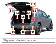
Installation Point(s): S1, S2
| Battery-Powered | Yes |
| T-Connector Location | S1,S2 |
| Tail Light Circuits | 7.5 Amps |
| Turn and Brake Circuits | 5.0 Amps |
| Converter Type | Universal, Potted, Powered, Protected, PWM |
| Electrical Component Location | Vehicle / Trailer |
| Electrical Package Type | Packaged |
| Electrical System Type | 2W |
| Material | THERMOPLASTIC RUBBER |
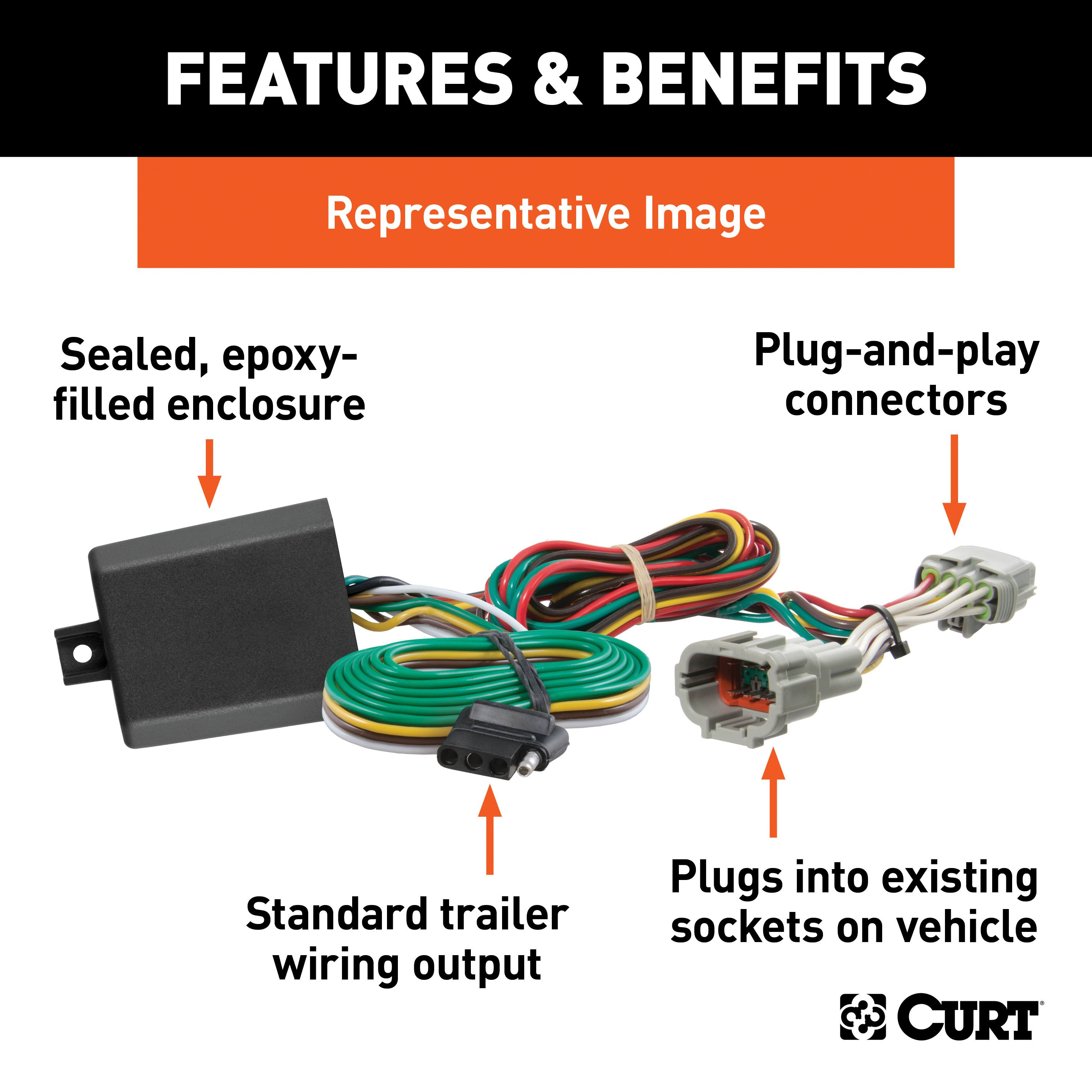
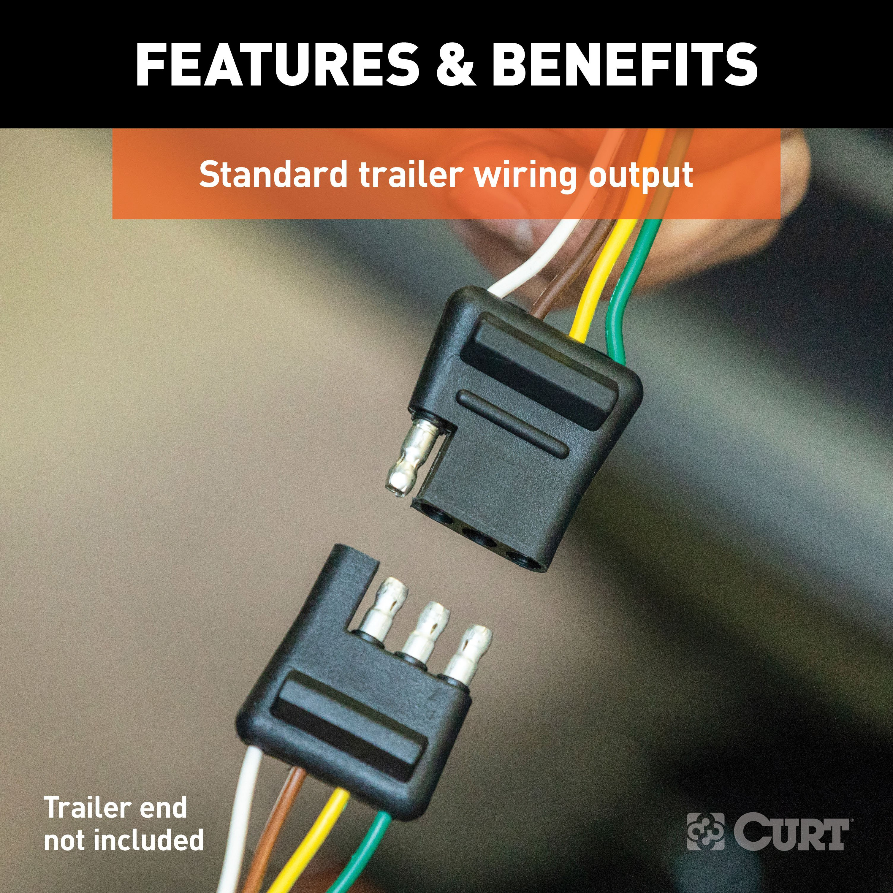
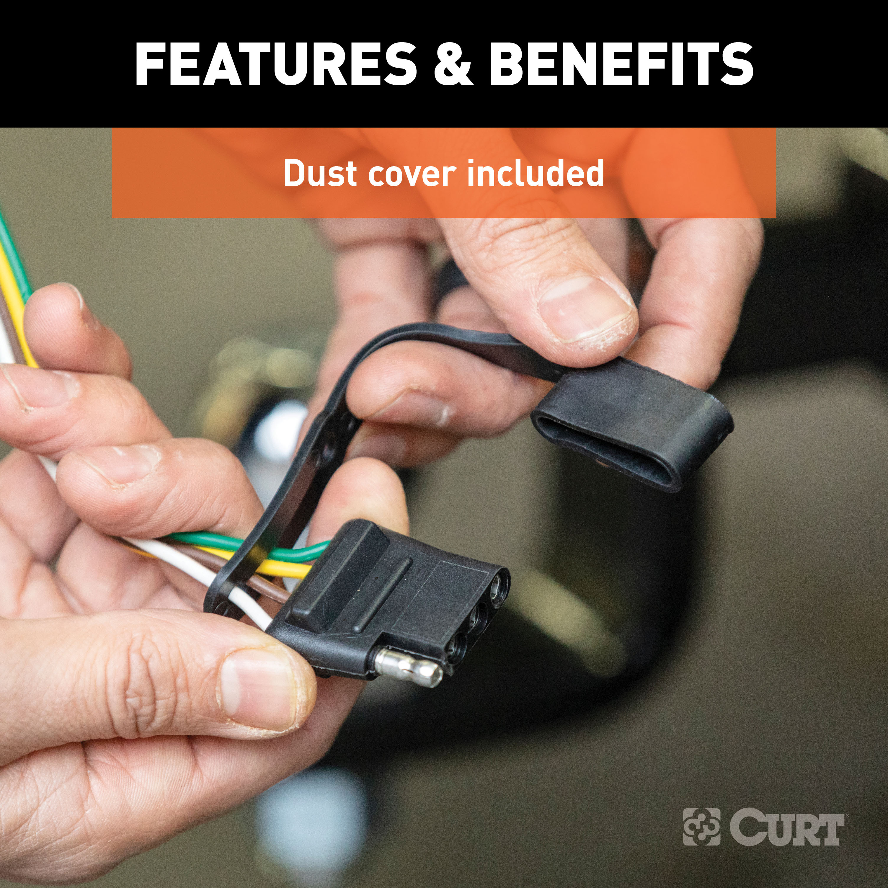
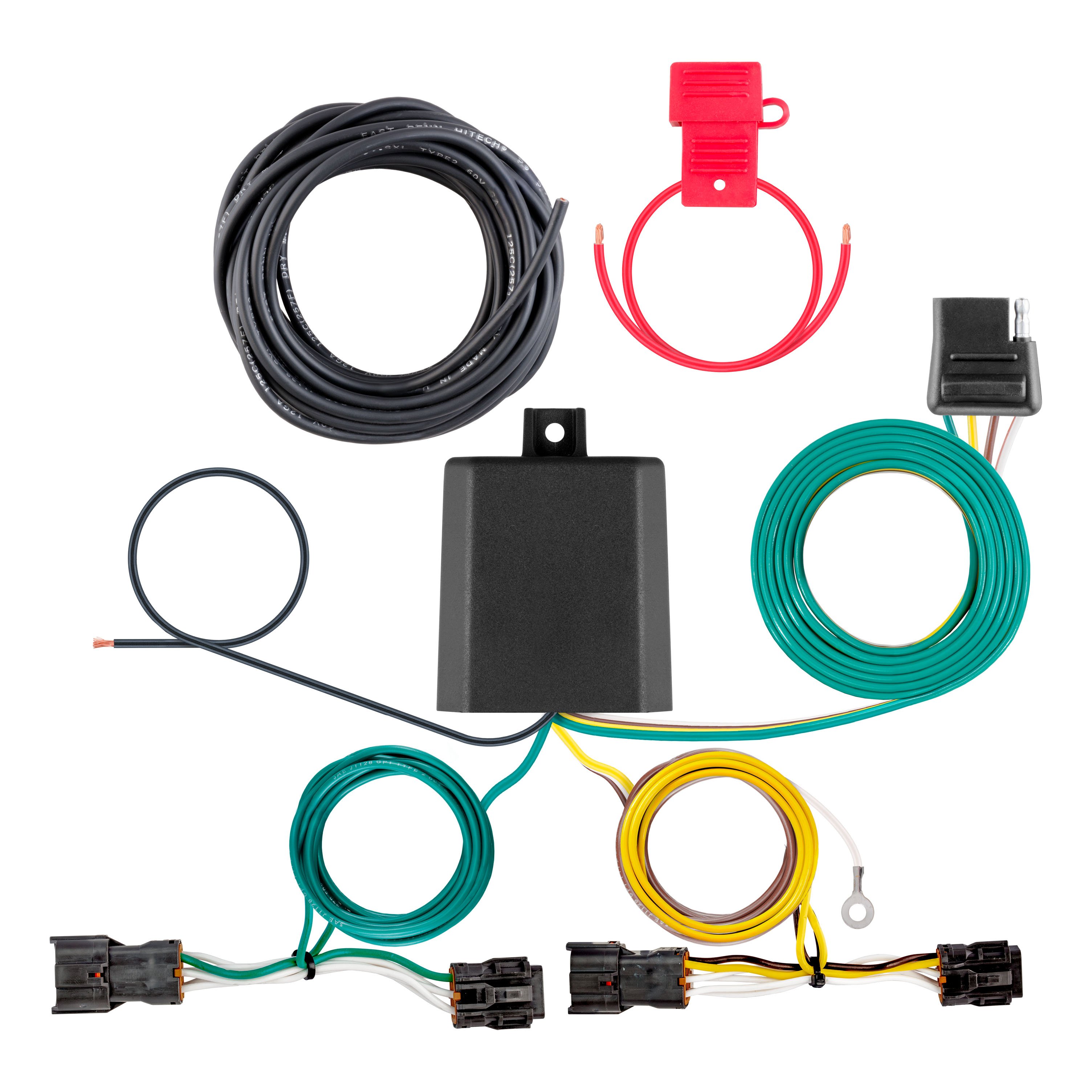
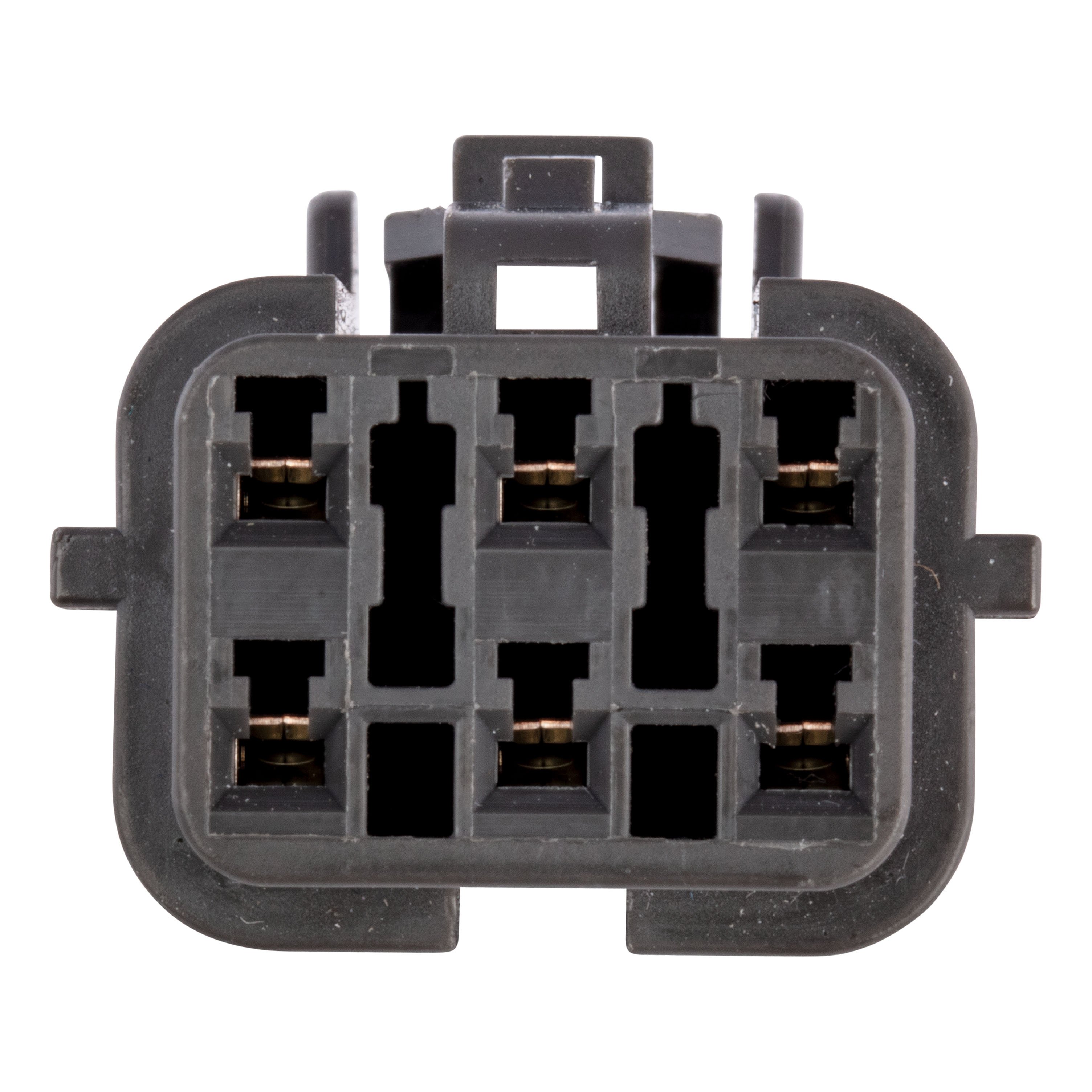
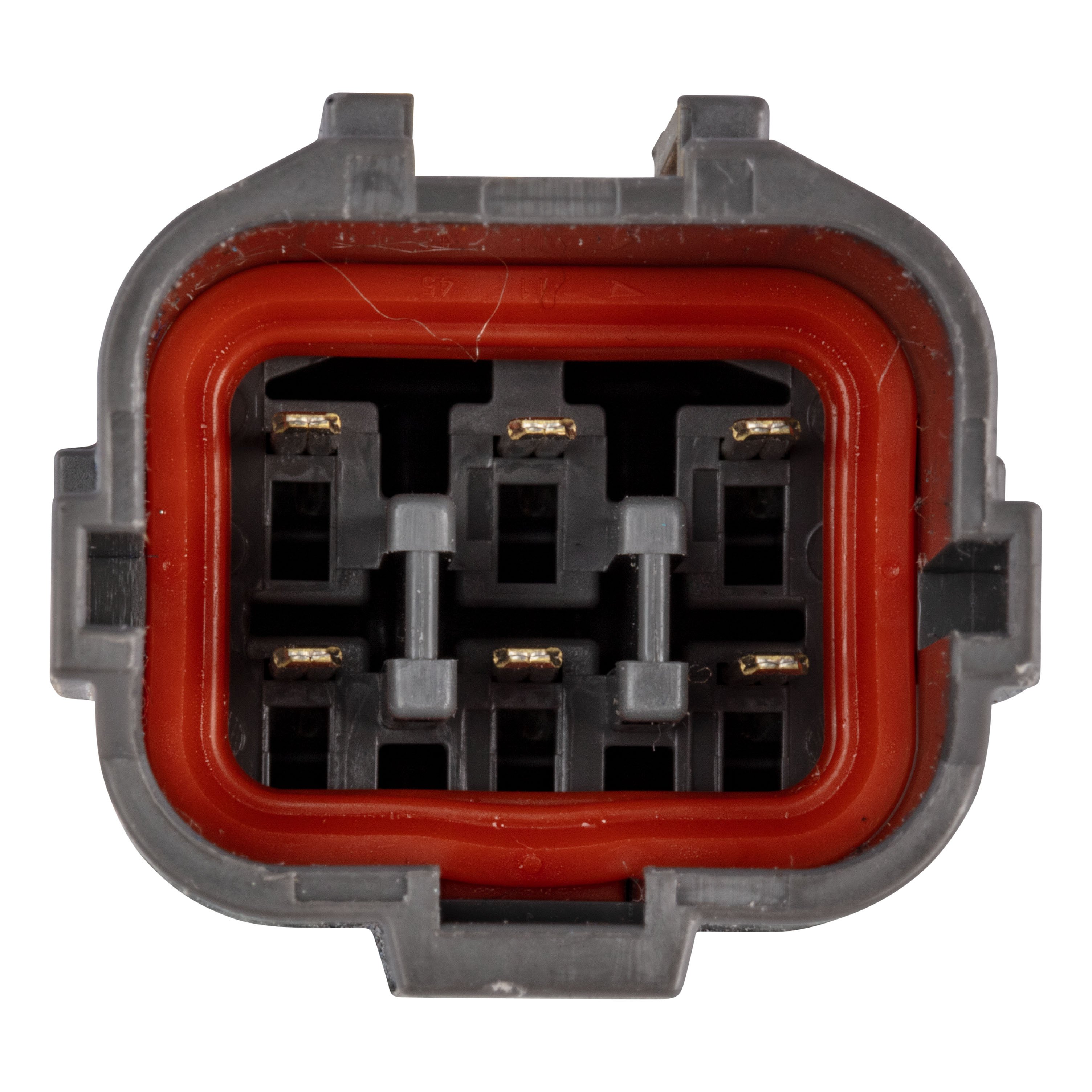
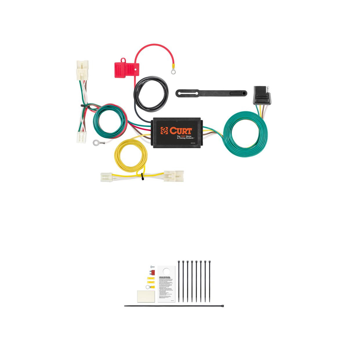
If your vehicle is not equipped with wiring for towing a trailer, CURT custom wiring is the ideal solution. A custom wiring harness -- also called a T-connector -- is a simple, plug-and-play electrical device that plugs into your automotive electric system and provides a standard, universal trailer wiring connection. This is done using two or more vehicle-specific, OEM-compatible connectors to plug into the taillight assembly, eliminating the need for cutting, splicing and soldering during installation. Custom wiring harnesses are made vehicle-specific, and while they are not available for all vehicles, they do offer one of the fastest, easiest and most secure ways to wire a vehicle for towing. This particular plug-in harness provides a 4-way flat connector socket and is designed to be a custom wiring harness to fit certain years of the Hyundai Santa Cruz (to verify your vehicle compatibility, see application info). It comes with all necessary wiring components to establish a reliable trailer wiring connection, as well as a dust cover to keep the connector clean when not in use. You have a picture in mind of your next destination -- maybe it's the boat landing at your favorite fishing spot, maybe it's a campsite that overlooks one of nature's masterpieces, or maybe it's the next big jobsite. However, turning that picture into a reality takes more than just daydreaming. It takes a solid connection and the right amount of power. CURT custom wiring is made with some of the most sophisticated technology in the industry and is designed to install with ease, giving you a long-lasting electrical connection for your towing hitch setup.

CURT offers a variety of high-quality trailer hitches and accessories for select vehicle models. Find the perfect fit for your towing needs at TowUniverse.
CURT, a Lippert brand, offers a complete line of towing products and is the leading manufacturer of custom-fit trailer hitches. We offer the broadest selection of custom-fit hitches, and each one is designed, welded, and coated in Wisconsin.
CURT is also a leader in flat towing products, as well as 5th wheel, gooseneck, and weight distribution hitches, ball mounts, electrical components, cargo solutions, and other towing accessories.
For everything from passenger cars and vans to full-size pickups and SUVs, CURT is 'The First Name in Towing Products®.'

Experts available to answer your questions
Call 888-634-9494One-Year Limited
Rediscover "Us" Time | Tested. Proven. Safe. Towing Products
1 compatible vehicles
| Year | Make & Model | Notes |
|---|---|---|
| 2025 - 2026 | Hyundai Santa Cruz | Installation time: 60-90 minutes |
The CURT 56553 Vehicle-Side Custom 4-Pin Trailer Wiring Harness, Fits Select Hyundai Santa Cruz (Part #BKDK56553) fits the following vehicles: 2025-2026 Hyundai Santa Cruz. Always verify your specific year, make, and model before ordering.
The CURT 56553 Vehicle-Side Custom 4-Pin Trailer Wiring Harness, Fits Select Hyundai Santa Cruz (Part #BKDK56553) fits 2025-2026 Hyundai Santa Cruz models. The 2026 model year is the last year covered by this part number. For newer models, check for an updated version.
Yes, the CURT 56553 Vehicle-Side Custom 4-Pin Trailer Wiring Harness, Fits Select Hyundai Santa Cruz (Part #BKDK56553) is designed to fit the 2025-2026 Hyundai Santa Cruz.
The CURT 56553 Vehicle-Side Custom 4-Pin Trailer Wiring Harness, Fits Select Hyundai Santa Cruz (Part #BKDK56553) Typical installation time is 60-90 minutes. Basic hand tools are typically all you need.
Part 56553 is a powered converter module wiring harness system for SUVs and vans. It converts factory vehicle lighting signals (turn, brake, and taillight) to a 4-flat trailer connector, allowing you to connect a trailer with functioning lights. The system includes a converter box, wiring harness with color-coded wires (yellow for left turn, green for right turn, red for brake, brown for taillight), power lead, ground wire, and all necessary fasteners and connectors.
Part 56553 is designed for SUVs and vans with 12-volt negative ground electrical systems. The manual does not list specific vehicle makes, models, or years. Contact Curt Manufacturing or consult a fitment database to confirm compatibility with your vehicle before purchasing.
No. Part 56553 is designed only for 12-volt negative ground electrical systems. Using it on 24-volt or positive ground systems will cause improper function and potential damage.
Required tools are: ratchet, ratchet extension, 10mm socket, wire cutters, wire crimpers, wire strippers, Phillips screwdriver, flathead screwdriver, fish wire, and trim panel tool. You will also need an abrasive pad or paper to clean rust and paint from the grounding area, and a drill with a 3/32" bit if a suitable existing screw is not available for the ground connection.
The kit includes: cable ties (for securing wires), double-sided tape (for mounting the converter module), a ground screw with ring terminal, a 4-flat dust cover, a fuse holder with 10-amp fuse, butt connectors, and a 12 GA power wire. The manual indicates these are supplied items, though it does not provide a complete itemized parts list.
Yes. Step 1 requires you to locate the vehicle battery in the engine compartment on the driver side and disconnect the negative battery terminal. Fasten this wire down and away from the battery while completing the installation. Do not reconnect the battery until Step 10, after all other wiring is complete.
The installation is rated as Difficult. Installation difficulty is based on time and effort involved and may vary depending on installer expertise, vehicle condition, and availability of proper tools and equipment.
Step 2: Open the tailgate and locate and remove the two 10mm bolts holding the taillights in place on each side. Step 3: Pull the taillight outwards from the side of the vehicle. Once removed, separate the connector from the taillight housing, taking care not to damage the locking tabs. Set the taillight aside and repeat on the other side.
Step 4: Underneath the vehicle on the driver side, locate the rear protective panel and remove the two 10mm plastic nuts and three push pins. Then remove the cover and set it aside. This provides access to route the wiring harness.
Fish-wiring is a technique to push or pull an electrical wire through a blind hole or cavity. For part 56553: (1) Insert fish wire (stiff wire, rope, string, or cut wire hanger) through the blind hole between the vehicle body and locate it on the other side. (2) Use tape to secure the harness to the fish wire. (3) Pull the harness back up through the cavity. If the wire gets hung up, push back down, wiggle it, or twist to loosen it. The manual warns to avoid damaging the tailgate dampening shock when fish-wiring between the shock and rear bed area.
Step 5: Starting from the driver side, fish wire down between the vehicle body to under the vehicle. Attach the housing with the yellow wire to the fish wire and pull up to the taillight opening. Locate the vehicle taillight wiring connector. Attach the connectors between the taillight harness and the factory connectors that were separated in Step 3. Reinstall the taillight into the mount. The yellow wire carries the left turn signal.
Step 6: Route the green wire to the bumper and down to the passenger side. Secure any loose wires with the provided cable ties. Repeat Step 5 with the connector containing the green wire, using the same fish-wiring technique to pull the harness up to the passenger side taillight opening and connect it to the factory connectors. The green wire carries the right turn signal.
Step 7 requires grounding the white ground wire. First, locate a suitable grounding point near the connector, such as an existing screw with nut in the vehicle frame. If no suitable existing screw is available, drill a 3/32" pilot hole for the provided ground screw. Before drilling, check for miscellaneous items that may be hidden behind or under any surface to avoid damage and personal injury. Clean the area of rust, dirt, and paint using an abrasive pad or paper.
If a suitable existing screw is not available, drill a 3/32" pilot hole for the provided ground screw. The area should be free of rust, dirt, and paint; use an abrasive pad or paper to clean it. Always check for hidden items before drilling.
Step 8: Locate a flat, clean surface behind the removed rear protective cover. Mount the light modules box using the supplied double-sided tape or cable ties. The module must be mounted in a protected area with the epoxy side down to prevent water buildup and debris collection. Failure to mount in a protected area can cause loss of warranty, product failure, overheating, and potential damage.
Step 8 and the Powered Converter Lead Instruction Sheet detail power connection: Route a 12 GA wire or larger from the converter to the vehicle battery location, avoiding pinch points and hot or rotating components. When passing the power wire through sheet metal, use an existing grommet, add a grommet, or use silicone to protect it from sharp edges. Connect the black power wire to the positive battery terminal using a ring terminal. Secure the power wire to the vehicle chassis using the provided cable ties. Install the fuse holder with a 10-amp fuse after all other steps are complete. The battery connection must be fuse-protected with a 10-amp maximum; exceeding this rating causes loss of warranty, overheating, and potential fire.
The color-coded wires on part 56553 are: Yellow = Left turn signal, Green = Right turn signal, Red = Brake signal, Brown = Taillight (running light). The white wire is the ground wire. These colors match standard trailer lighting conventions and connect to the corresponding factory vehicle lighting circuits.
Step 9: Route the 4-flat connector to the center of the vehicle. Secure any loose wires with the provided cable ties. The 4-flat connector is where you will plug in a trailer with functioning lights. Step 10 includes installing the provided 4-flat dust cover to help prevent corrosion.
The battery connection must be fuse-protected with a 10-amp maximum. Exceeding this rating causes loss of warranty, overheating, and potential fire. The fuse holder with a 10-amp fuse is provided and must be installed after all other steps are complete.
Part 56553 has the following electrical ratings: Signal circuits (left and right turn) = 3.0 amps per side; Tail/Running circuits = 6.0 amps total. Do not exceed the product rating or the tow vehicle lamp load rating, whichever is lower.
Key safety precautions: (1) Disconnect the negative battery terminal before beginning and fasten it down and away from the battery. (2) Do not lay tools across the positive battery terminal (red covers or '+' symbol) to avoid shorts, sparks, and electrical shocks. (3) Do not ground the negative cable to a metal item during installation; this damages the vehicle's electrical system. (4) Check for hidden items before drilling to avoid personal injury and property damage. (5) Avoid damaging the tailgate dampening shock when fish-wiring. (6) Route the power wire avoiding pinch points and hot or rotating components. (7) Use a grommet or silicone when passing the power wire through sheet metal to protect from sharp edges. (8) Mount the converter module in a protected area to prevent water buildup and debris collection.
Step 10 and the Notice on page 4 require verification that the harness is functioning after installation. Test by: (1) Attaching the 4-flat connector to any trailer with functioning lights, or (2) Using a 4-flat tester, test light, or multimeter to verify proper signal and power. Do not operate the vehicle with a trailer until testing confirms proper function.
Step 10: Reconnect the negative battery terminal. Install the provided 4-flat dust cover to help prevent corrosion. Reinstall all removed items (taillights, rear protective panel, tailgate) in the reverse order of disassembly. Test the harness for proper function using a trailer with functioning lights, a 4-flat tester, test light, or multimeter before operating the vehicle.
Periodic inspection of all wires and connections should be performed to ensure there is no visible damage or loose connections. The manual does not specify an inspection interval; consult the vehicle owner's manual or contact the vehicle manufacturer for maintenance recommendations.
Yes. Disconnect the negative battery terminal before starting and fasten it away from the battery. Reconnect only after all wiring is complete in Step 10.
Drilling is required only if a suitable existing screw is not available for the ground connection. If needed, drill a 3/32" pilot hole. Always check for hidden items before drilling.
Do not lay tools across the positive battery terminal (red covers or '+' symbol) during installation; this causes shorts, sparks, and electrical shocks. Also, the battery connection must be fuse-protected at 10 amps maximum to prevent overheating and fire.
If the fish wire or harness gets hung up on something during the fish-wiring process, try the following: (1) Push the wire back down, (2) Wiggle it around to loosen it, or (3) Twist the wire to loosen it from what it is hung up on. If the issue persists, you may need to reposition the fish wire entry point or use a different routing path. Avoid damaging the tailgate dampening shock when working in the rear area.
If the double-sided tape is not holding the converter module securely, use cable ties instead to secure the module to a suitable mounting point behind the rear protective cover. Ensure the mounting surface is clean and flat, and that the module is positioned with the epoxy side down. The module must be mounted in a protected area to prevent water buildup and debris collection.
Verify the following: (1) The negative battery terminal is reconnected. (2) The 10-amp fuse is installed in the fuse holder and is not blown. (3) All wire connectors are fully seated and not damaged, especially the taillight connectors separated in Step 3. (4) The white ground wire is securely attached to the vehicle frame with the ring terminal and ground screw. (5) The black power wire is connected to the positive battery terminal with a ring terminal. (6) All wires are routed correctly and not pinched or damaged. (7) Test using a trailer with functioning lights, a 4-flat tester, test light, or multimeter to identify which circuit is not functioning (left turn, right turn, brake, or taillight).
Free Shipping
Ships free on all orders
 Authorized Dealer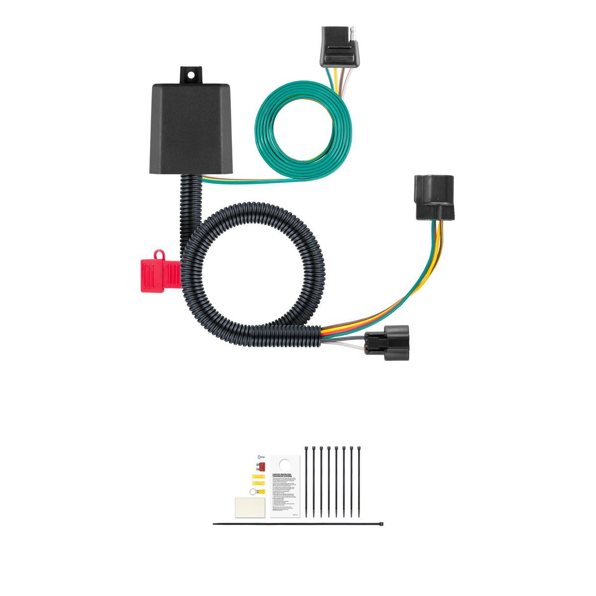


Quick Ship
In stock and ready to ship — order now!
Shipping from Eau Claire, WIFREE SHIPPING
Estimated delivery Mon, Sep 28 - Wed, Sep 30
Order before 2 PM EST Monday–Friday for same-day processing
Guaranteed safe & secure checkout
No reviews have been added for this product.