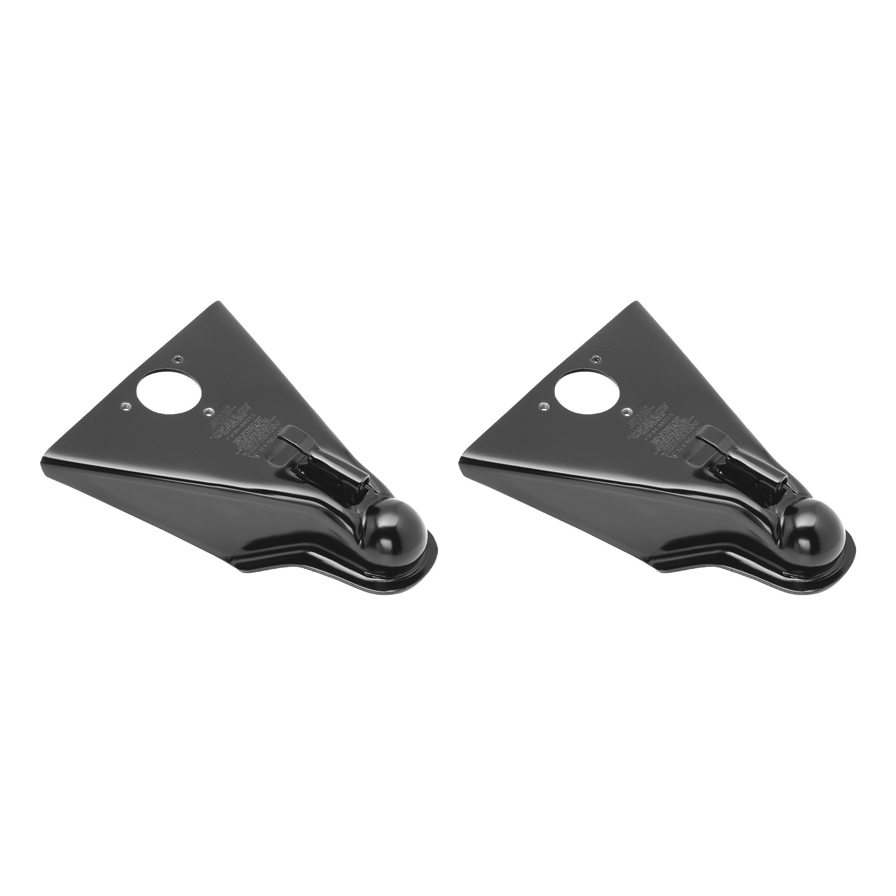
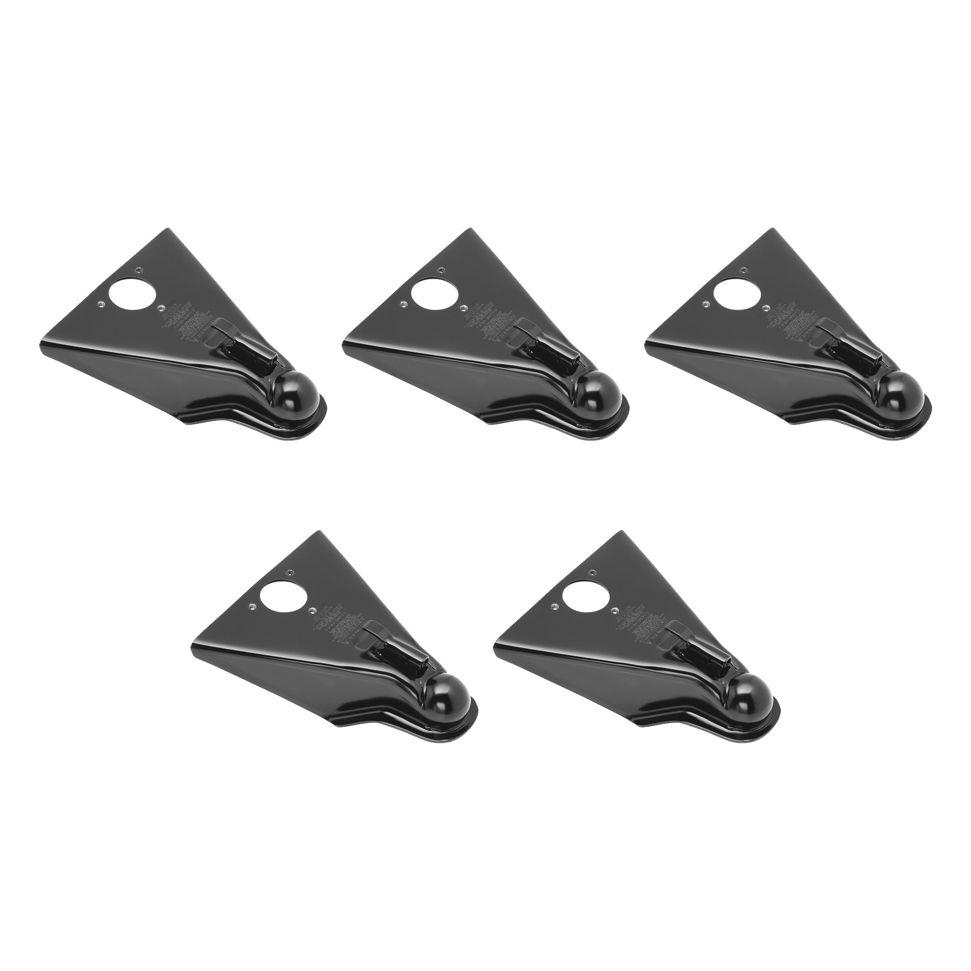
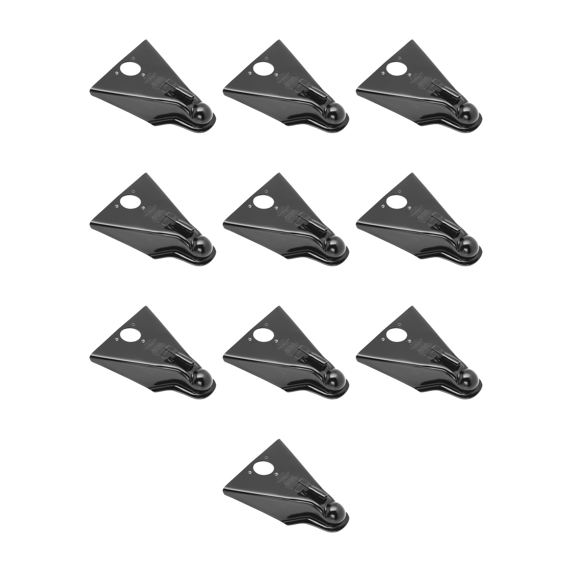
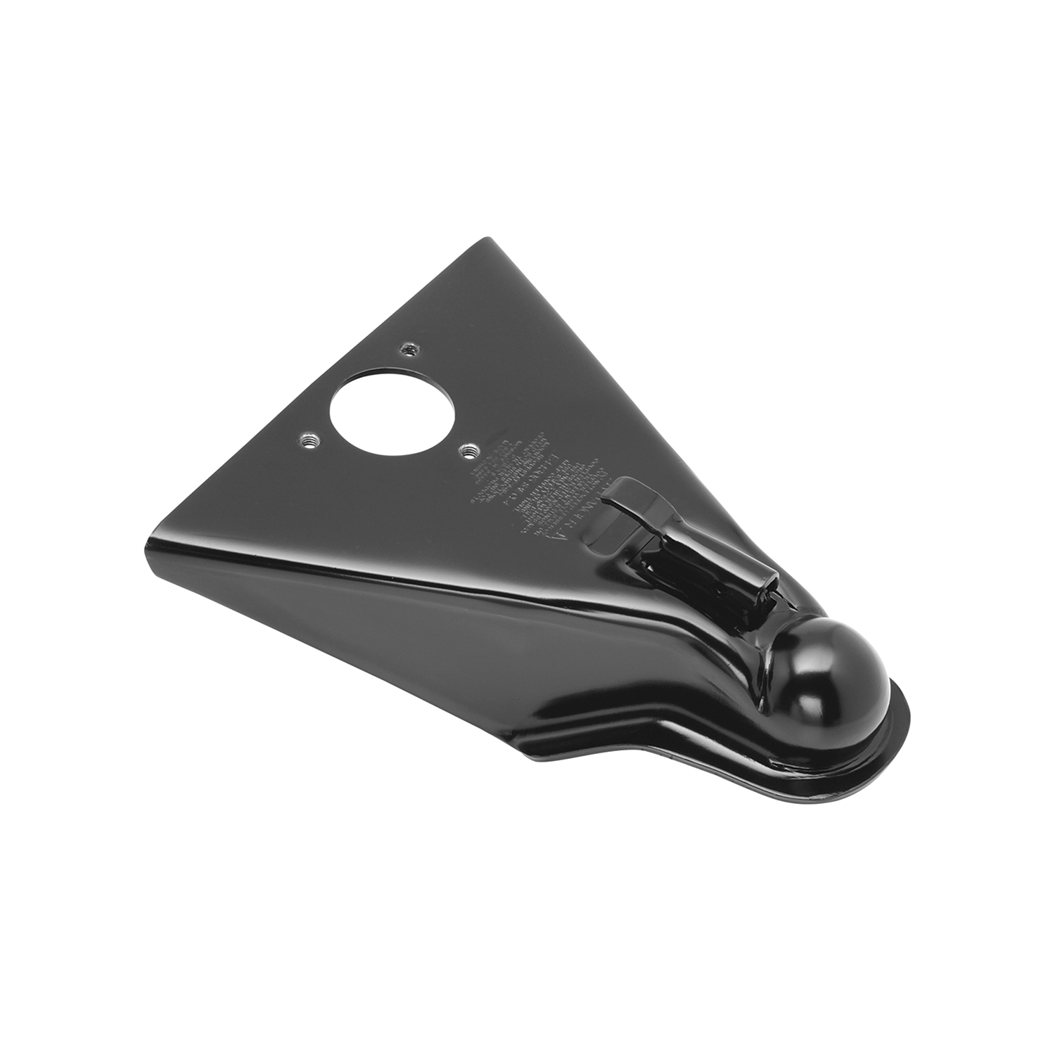
Fulton (2-Pack) A-Frame Coupler, 2-5/16 Inch Diameter, Round Jack Hole, Weld-On, 10,000 lbs. Capacity, BlackFulton$111.96Out of Stock
View productOur in-house experts typically reply within one business day.

Fulton

Always the correct part
We know our products
Quality Products
Free Shipping!
Always the correct part
We know our products
Quality Products
Free Shipping!
Free Shipping
Ships free on all orders
 Authorized Dealer


FREE ShippingFREE SHIPPING
Estimated delivery Tue, Aug 11 - Fri, Aug 14
Order before 2 PM EST Monday–Friday for same-day processing
Guaranteed safe & secure checkout
Complete kit bundle containing all necessary components for your project. Professional-grade components designed for reliable performance and long-lasting durability.

Keywords: FLE443050303-5PK bundle kit, complete kit, professional components, industrial kit, FLE443050303, Fulton

Fulton has produced marine and utility trailer hardware for more than a century, and its jacks, winches and couplers are a standard for light and medium-duty trailering. The XLT and F2 series cover swivel and fixed jacks, hand and powered winches from 1,500 to 3,200 pounds, and couplers built to keep working in wet, salty conditions.
With more than a hundred years of production behind it, Fulton has become the reference point for light and medium-duty trailer hardware, particularly on the marine side. That environment is the toughest test a trailer component faces. A boat trailer is reversed into fresh or salt water on every launch and left to sit wet, which finds every weakness in plating, sealing and material choice. Fulton's stated position is that the brand performs best when the weather is at its worst, and its product engineering reflects that. It sits within the Horizon Global towing group alongside Reese, Draw-Tite, Bulldog, Tekonsha and Wesbar.
Marine and utility jacks anchor the line. The XLT Series marine jack uses a bolt-through swivel mount built from three-dimensionally formed heavy-gauge steel stampings with a proprietary bushing material, a combination chosen to minimise deflection under tongue load while keeping the swivel action working after years of exposure. The F2 Series takes corrosion resistance further as the industry's only extruded aluminium marine jack with an anodised finish, which removes the rust problem at its source rather than coating over it. The wider trailer jack range covers topwind, sidewind and drop-leg configurations.
Trailer winches pull boats onto bunks and rollers. XLT Series winches use efficient gear ratios, full-length drum bearings, oil-impregnated shaft bushings and a Comfort Grip handle that makes the last few turns under load bearable, in 1,500 and 1,800 pound capacities. F2 Series winches use an enclosed frame for a cleaner look and added protection, in 1,600, 2,000 and 3,200 pound models, including two-speed options that trade line speed for cranking effort.
Couplers complete the range, including A-frame couplers matched to common tongue sizes and load ratings, serving boat owners, utility trailer users and trailer manufacturers.
Experts available to answer your questions
Call 888-634-94945 Years
A stamped coupler is a hitch coupler that connects a trailer tongue to a towing vehicle's hitch ball. It allows the trailer to be towed and uncoupled when needed. This manual covers both bolt-on couplers (fastened with bolts and nuts) and weld-on couplers (permanently welded to the trailer tongue). The coupler must be properly installed and maintained to safely support the trailer load.
This manual covers Class 1, 2, 3, and 4 stamped couplers. The installation method and fastener size vary by class. Class 1 couplers use 3/8 inch grade 5 bolts, while Class 2, 3, and 4 couplers use 1/2 inch grade 5 bolts. Consult the coupler body or contact Cequent Performance Products at 1-800-632-3290 to confirm which class is appropriate for your trailer.
No. This manual covers two tongue types: straight tongue couplers and A-frame couplers. A-frame couplers can only be used with 50-degree trailer tongues. Straight tongue couplers are used with standard straight tongues. Do not use an A-frame coupler with any other tongue angle. Verify your trailer tongue type before purchasing.
Use only the proper ball size as indicated on the coupler body itself. The correct ball size is marked on the coupler. If you are uncertain which ball size is correct, contact Cequent Performance Products at 1-800-632-3290 or visit www.cequentgroup.com. Using an incorrect ball size will prevent proper seating and safe operation.
For Class 1 couplers, the preferred method is to use four (4) 3/8 inch grade 5 bolts through the side holes. An alternate method is to use two (2) 3/8 inch grade 5 through bolts and locknuts, provided they can be torqued to the appropriate SAE proof load specification of 23 ft. lbs. Use only grade 5 hardware. No deformation of the trailer tongue end is allowed.
For Class 2, 3, and 4 couplers, the preferred method is to use four (4) 1/2 inch grade 5 bolts through the side holes. An alternate method is to use two (2) 1/2 inch grade 5 through bolts and locknuts, provided they can be torqued to the appropriate SAE proof load specification of 55 ft. lbs. Use only grade 5 hardware. No deformation of the trailer tongue end is allowed.
For A-frame couplers, use the available mounting holes in the coupler housing and bolt the coupler to the tongue members using grade 5 hardware with locknuts. For couplers using 1/2 inch hardware, use washers beneath all bolt heads and locknuts. Torque grade 5 bolts with locknuts to the appropriate SAE proof load specification: 55 ft. lbs. for 1/2 inch bolts. No deformation of the trailer tongue end is allowed.
The adjustable height channel mounting bracket requires two (2) 5/8 inch by 5 inch grade 5 bolts. These bolts are inserted through two sets of holes in the mounting bracket and the coupler holes. Locknuts are tightened to 100–110 ft. lbs. The hardware is provided with the mounting bracket.
Yes, gussets are required if your trailer tongue height is 6 inches or less. Gussets are structural reinforcements that support the mounting bracket. If your tongue is taller than 6 inches, gussets are not required. The mounting bracket must be centered on the tongue and remain vertical after installation.
For weld-on couplers, a minimum coupler/tongue overlap of 6.5 inches is required. The coupler's internal stop must be butted against the end of the trailer tongue to achieve maximum overlap. This overlap is critical for proper load support and safety.
Yes. Before mounting the coupler, confirm that there will be no interference from the tow vehicle, tongue, ground, and any other mounted accessories while stationary or in motion. Check for interference in both open and closed positions before installing. Check for interference again after installation is complete. If interference is found, do not use the coupler.
1. Assure the coupler's internal stop is butted against the end of the trailer tongue for maximum overlap. 2. For Class 1 couplers, insert four 3/8 inch grade 5 bolts through the side holes (or use two through bolts and locknuts as an alternate). For Class 2, 3, and 4 couplers, insert four 1/2 inch grade 5 bolts through the side holes (or use two through bolts and locknuts as an alternate). 3. Tighten bolts to the appropriate SAE proof load specification: 23 ft. lbs. for 3/8 inch bolts or 55 ft. lbs. for 1/2 inch bolts. 4. Ensure no deformation of the trailer tongue end occurs.
A-frame couplers can only be used with 50-degree trailer tongues. 1. Use the available mounting holes in the coupler housing. 2. Bolt the coupler to the tongue members using grade 5 hardware with locknuts. 3. For couplers using 1/2 inch hardware, place washers beneath all bolt heads and locknuts. 4. Torque grade 5 bolts with locknuts to 55 ft. lbs. (for 1/2 inch bolts). 5. Ensure no deformation of the trailer tongue end occurs.
1. Confirm the mounting bracket will not interfere with the tow vehicle, tongue, ground, or other accessories in open and closed positions. 2. Center the mounting bracket on the tongue and ensure it remains vertical after installation. 3. If tongue height is 6 inches or less, install gussets. 4. A 1/4 inch minimum fillet weld is required all around the bracket. 5. Insert two 5/8 inch by 5 inch grade 5 bolts through two sets of holes in the mounting bracket and coupler. 6. Tighten locknuts to 100–110 ft. lbs. 7. After installation, verify that coupler operation has not been impaired.
Torque 3/8 inch grade 5 bolts to 23 ft. lbs. This applies to Class 1 coupler installations using the preferred method of four bolts through side holes, or the alternate method of two through bolts and locknuts.
Torque 1/2 inch grade 5 bolts to 55 ft. lbs. This applies to Class 2, 3, and 4 coupler installations using the preferred method of four bolts through side holes, or the alternate method of two through bolts and locknuts. It also applies to A-frame coupler installations.
Torque 5/8 inch grade 5 bolts to 110 ft. lbs. This applies to the adjustable height channel mounting bracket, which uses two 5/8 inch by 5 inch bolts with locknuts.
Tighten the locknuts on the two 5/8 inch by 5 inch grade 5 bolts to 100–110 ft. lbs. This is the specified torque range for the mounting bracket hardware.
The manual does not address electrical connections for the coupler itself. However, the manual does require that all trailer lighting be hooked up and working properly before towing. Refer to your trailer manufacturer's instructions for lighting installation and connections.
Before towing, perform the following checks: 1. Check the vehicle, mounting bracket, hitch, hitch ball, and coupler for signs of wear or damage. 2. Verify the coupler handle opens and closes freely. 3. If the coupler or mounting bracket is deformed or damaged, replace the complete coupler and mounting bracket. 4. Replace any bent, broken, or worn parts. 5. Close the coupler securely, ensuring the hitch ball is fully seated in the coupler ball pocket and the handle or latch is in the closed position. 6. Check mounting bracket hardware for wear and proper tightness; tighten to appropriate SAE proof load specifications using only grade 5 hardware. 7. Verify trailer safety chains are properly connected according to SAE J684. 8. Ensure all trailer lighting is hooked up and working properly.
Do not exceed the lesser of the weight ratings for the mounting bracket, coupler, hitch, vehicle, ball, or trailer (including load). Weigh your trailer plus any added load before towing. The coupler must be rigidly attached to the trailer to support its maximum rated load according to SAE J684. Consult the coupler body, mounting bracket documentation, and your vehicle and trailer specifications to determine the applicable weight limit.
No. Do not tow if the ball is not fully seated in the coupler ball pocket or if the coupler is not closed. Before towing, verify that the hitch ball is fully seated and the coupler handle or latch is in the closed position. If the ball is not seated with the lever in the closed position and the latch engaged, do not tow. Repeat the coupling steps until the ball is properly seated.
Always block the trailer wheels before latching or unlatching the coupler. This prevents the trailer from moving unexpectedly during the coupling or uncoupling process. Additionally, use caution when uncoupling, as the tongue may rise suddenly due to negative tongue load.
Operator and bystanders should never position any part of the body under any portion of the coupler or the load being supported. Do not allow children to play on or around the coupler or the load being supported. These precautions prevent serious injury from the coupler or load shifting or falling.
Do not use the coupler if its operation has been impaired in any way after installation. After installing the mounting bracket and/or coupler, check that the coupler operation has not been impaired. If coupler operation has been impaired, do not use it. Contact Cequent Performance Products at 1-800-632-3290 for assistance.
After installation is complete, perform the following checks: 1. Verify that the coupler operation has not been impaired in any way. 2. Check for interference between the coupler and the tow vehicle, tongue, ground, or other mounted accessories in both open and closed positions. 3. If the coupler is to be primed or painted, remove excess paint or primer buildup from the ball pocket and latching mechanism. 4. Do not use the coupler if its operation has been impaired.
The following maintenance procedures should be performed at least annually: 1. Check welds and mounting bolt torque. Retighten bolts to appropriate SAE proof load specifications if needed. 2. Grease the ball pocket. 3. Oil pivot points with SAE 30 weight motor oil. Additionally, keep the ball pocket and mechanism clean at all times. When parking or storing the trailer, keep the coupler off the ground so dirt and other foreign material will not build up in the coupler ball pocket.
Check welds and mounting bolt torque at least annually. Retighten bolts to the appropriate SAE proof load specifications if they have loosened. For bolt sizes, use: 23 ft. lbs. for 3/8 inch bolts, 55 ft. lbs. for 1/2 inch bolts, and 110 ft. lbs. for 5/8 inch bolts. Regular inspection helps ensure the coupler remains safe and secure.
Oil pivot points with SAE 30 weight motor oil. This should be done at least annually as part of regular coupler maintenance.
This manual covers Class 1, 2, 3, and 4 stamped couplers for straight tongue or 50-degree A-frame trailers. Verify your trailer tongue type and coupler class (marked on the coupler body). For fitment confirmation, contact Cequent Performance Products at 1-800-632-3290.
Use four 3/8 inch grade 5 bolts (preferred) or two 3/8 inch grade 5 through bolts with locknuts. Torque to 23 ft. lbs.
Use four 1/2 inch grade 5 bolts (preferred) or two 1/2 inch grade 5 through bolts with locknuts. Torque to 55 ft. lbs.
Yes. Gussets are required if tongue height is 6 inches or less. They provide structural support for the mounting bracket.
Tighten the two 5/8 inch bolts on the adjustable height channel mounting bracket to 100–110 ft. lbs.
No. Do not tow if the ball is not fully seated in the coupler ball pocket or if the coupler is not closed. Verify proper seating before every tow.
Check welds and bolt torque, grease the ball pocket, and oil pivot points with SAE 30 weight motor oil. Keep the ball pocket and mechanism clean.
If the coupler handle does not open and close freely, the coupler operation may be impaired. Do not use the coupler. Check for the following: 1. Excess paint or primer buildup in the ball pocket or latching mechanism (if the coupler was recently painted). 2. Dirt or foreign material in the ball pocket or mechanism. Clean the coupler thoroughly. 3. Deformation or damage to the coupler housing or latch mechanism. If cleaning does not resolve the issue, the coupler may be damaged and must be replaced. Contact Cequent Performance Products at 1-800-632-3290.
If the hitch ball is not fully seated in the coupler ball pocket, do not tow. 1. Verify you are using the correct ball size for the coupler (size is marked on the coupler body). 2. Open the coupler fully and lower it over the hitch ball again, ensuring the ball enters the pocket completely. 3. Close the coupler handle or latch and verify the ball is fully seated and the ball clamp is below the ball. 4. If the ball still does not seat properly, check for dirt or debris in the ball pocket and clean it. 5. If the problem persists, the coupler or ball may be damaged. Do not tow. Contact Cequent Performance Products at 1-800-632-3290.
If the coupler latch does not engage or stay closed, do not tow. 1. Verify the hitch ball is fully seated in the ball pocket. 2. Check that the latch handle or lever is being moved to the fully closed position. 3. For Fas-Lok style couplers, verify the latch trigger is fully engaged by lifting up on the back of the locking lever. 4. For Yoke-style couplers, ensure the latch handle tips are fully entered into the slots on top of the coupler. 5. For Low-Latch couplers, ensure the latch handle tips are fully entered into the slots on top of the coupler. 6. If the latch still does not engage, check for dirt, debris, or deformation in the latch mechanism and clean or repair as needed. 7. If the problem persists, the coupler may be damaged. Do not tow. Contact Cequent Performance Products at 1-800-632-3290.
If mounting bracket bolts are loose, tighten them immediately before towing. 1. Identify the bolt size: 3/8 inch, 1/2 inch, or 5/8 inch. 2. Tighten to the appropriate SAE proof load specification: 23 ft. lbs. for 3/8 inch bolts, 55 ft. lbs. for 1/2 inch bolts, or 100–110 ft. lbs. for 5/8 inch bolts. 3. Use only grade 5 hardware. 4. Check all bolts regularly, at least annually, as part of routine maintenance. 5. If bolts repeatedly loosen, the mounting bracket or tongue may be damaged. Inspect for cracks or deformation and contact Cequent Performance Products at 1-800-632-3290 if damage is found.
If the coupler interferes with the tow vehicle, tongue, ground, or other accessories in open or closed position, do not use the coupler. 1. Check that the mounting bracket is centered on the tongue and remains vertical. 2. Verify the coupler's internal stop is butted against the end of the trailer tongue. 3. If the mounting bracket is not vertical or centered, loosen the bolts, reposition the bracket, and retighten to the appropriate torque. 4. If interference persists after repositioning, the coupler or mounting bracket may not be compatible with your trailer or tow vehicle. Contact Cequent Performance Products at 1-800-632-3290 for assistance.
No reviews have been added for this product.