

Tekonsha ModuLite HD Plus Protector w/Integrated Circuit & Overload Protection Trailer Light Power ModuleTekonsha$100.07In Stock
View productOur in-house experts typically reply within one business day.

Tekonsha

Always the correct part
We know our products
Quality Products
Free Shipping!
Always the correct part
We know our products
Quality Products
Free Shipping!
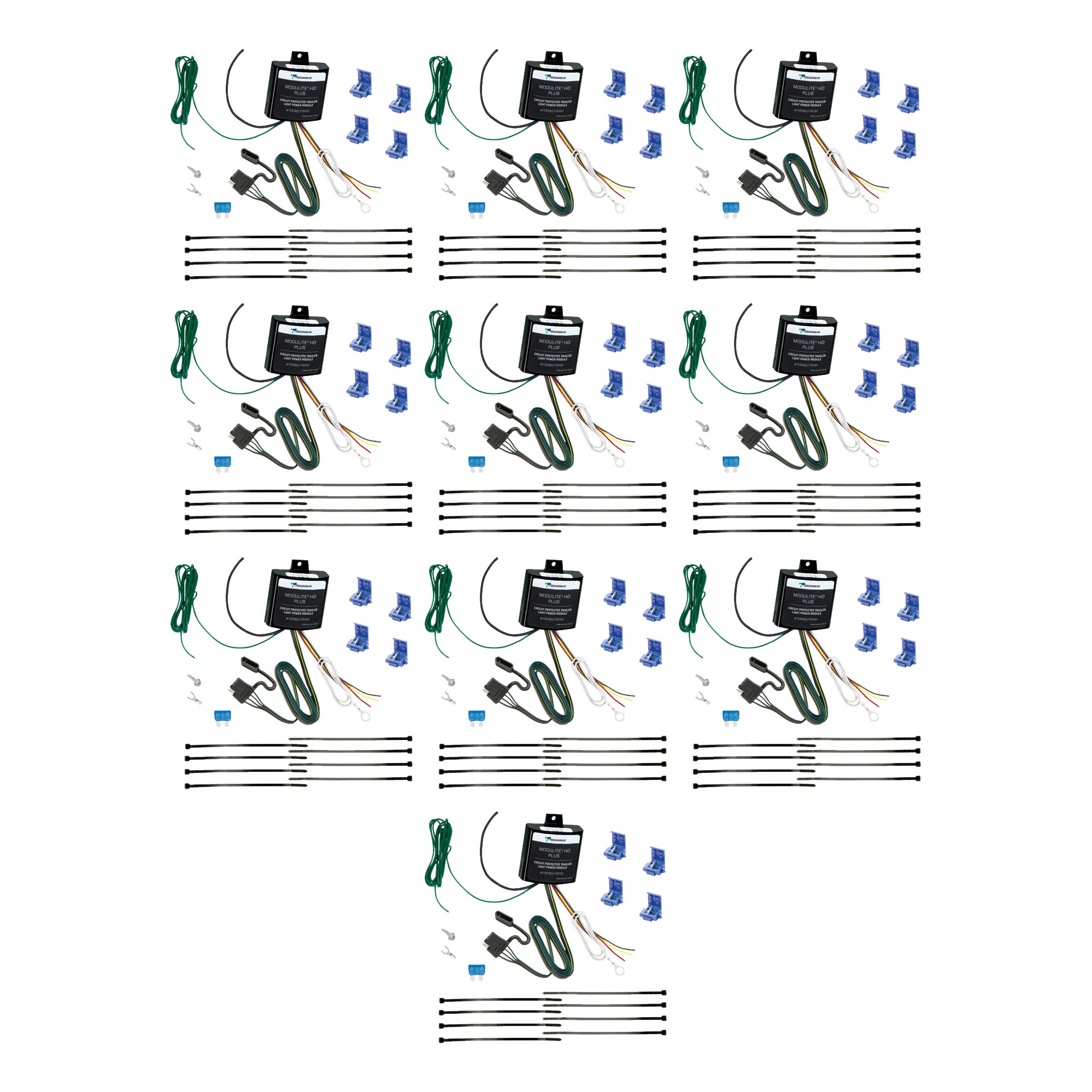
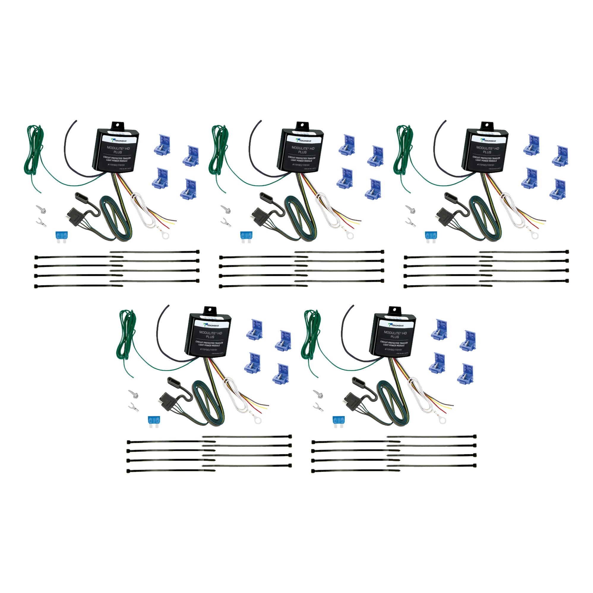
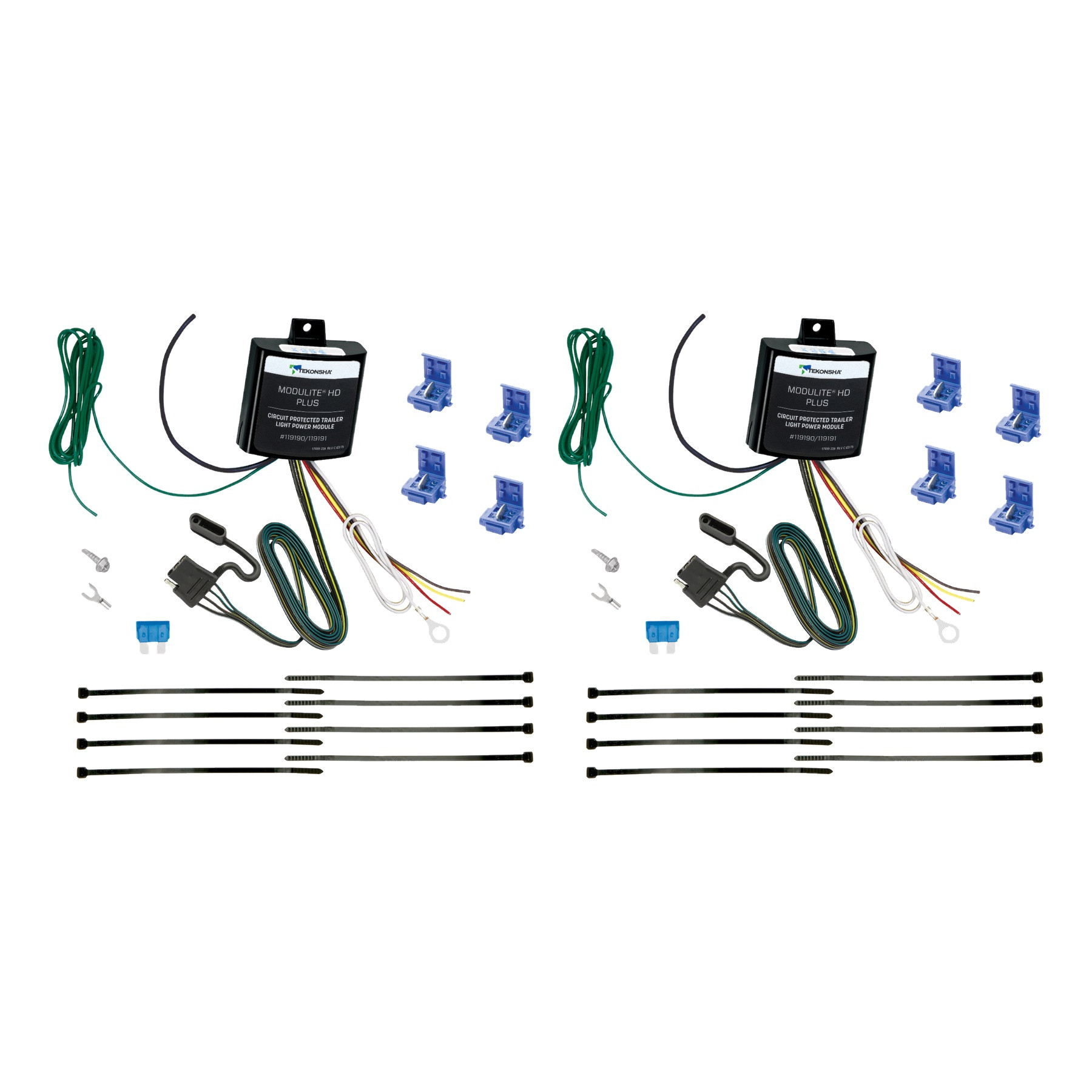
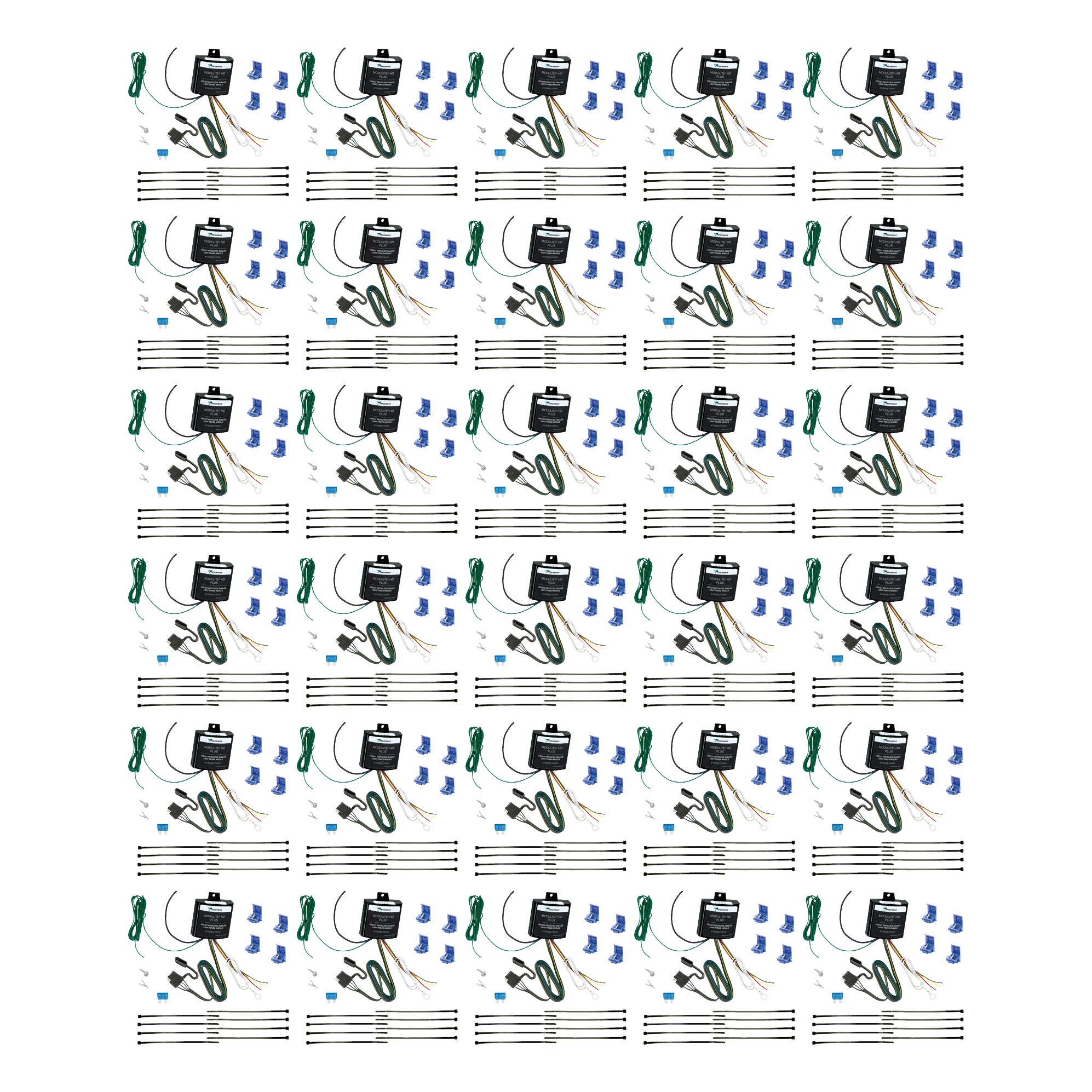
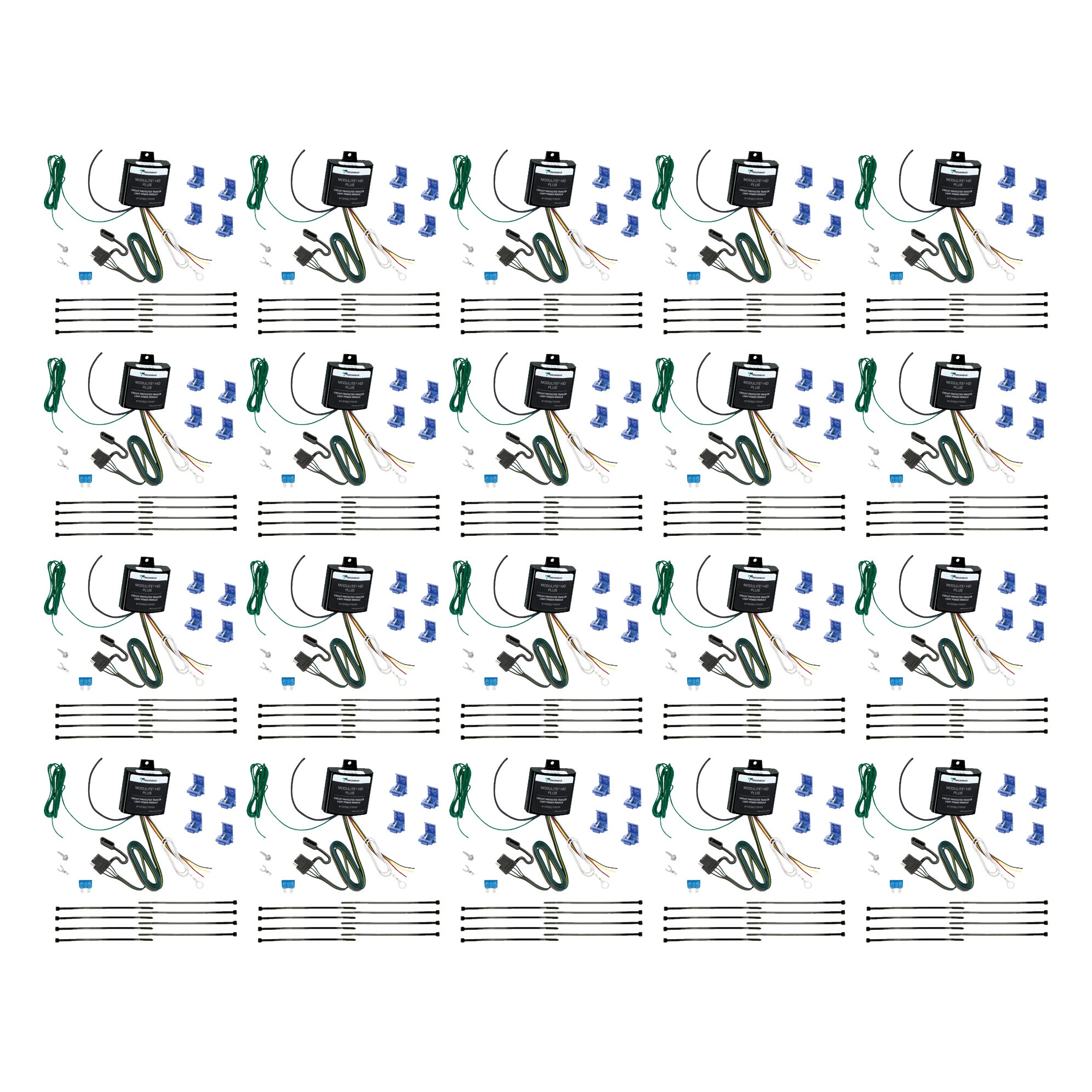
Complete kit bundle containing all necessary components for your project. Professional-grade components designed for reliable performance and long-lasting durability.

Does your trailer have multiple tail lights or does the tail lights seem dim to you? Then it is possible you need a Modulite from Tekonsha. The Tekonsha Modulite product line has power modules designed to virtually eliminates additional electrical draw on the vehicle's tail light circuits. They help to ensures maximum trailer light brightness for your trailer tail lights. It powers the trailer's stop, turn, tail and running lights without overloading your vehicle electrical systems.
*Will not work with all 2016 2021 Mercedes GLC300 models
| BRAND: | TEKONSHA |
| PART NUMBER: | 119190 |
| WARRANTY: | LIMITED 1 YEAR WARRANTY |
| WEIGHT: | 0.95 LBS |
| UNIVERSAL OR SPECIFIC FIT: | UNIVERSAL |
| TERMINAL QUANTITY: | 4 |
| WIRING HARNESS INCLUDED: | YES |
| CONVERTER TYPE: | Powered |
| CONNECTOR SHAPE: | RECTANGLE |
| ILLUMINATED: | NO |


Keywords: TK119190-10PK bundle kit, complete kit, professional components, industrial kit, TK119190, Tekonsha

Tekonsha is a leading manufacturer of electronic trailer brake controllers, pioneering the category in the 1970s. The lineup spans proportional units such as the Prodigy P3 and Prodigy iD, time-delayed controllers, the wireless Prodigy RF, plus vehicle-specific wiring harnesses, adapters and trailer brake components engineered for smooth, predictable stopping at any speed.
Tekonsha Engineering Company began in 1964 building RV steps and mirrors. Within a few years it had found its real calling, and by the 1970s Tekonsha was pioneering the manufacture of electronic trailer brake controllers, the product category that still defines the brand. More than half a century later it remains the reference name in trailer braking and is part of the Horizon Global group alongside Reese, Draw-Tite, Fulton, Bulldog and Wesbar.
A brake controller is the component that tells a trailer's electric brakes how hard to work and when, and getting that right is the difference between a controlled stop and a shove from behind. Tekonsha builds both major types. Proportional controllers use an internal accelerometer to sense how quickly the tow vehicle is slowing and apply trailer braking to match, so light braking stays light and hard braking is immediate. Time-delayed controllers ramp to a preset output over a fixed interval, a simpler and more economical approach that suits occasional towing.
The current brake controller range covers most of that ground. The Prodigy iD pairs with a phone through Tekonsha's EDGE technology for setup and monitoring, the P3 offers storable settings for multiple trailers and a trilingual colour LED display, the Prodigy P2 adds a dimmable display and boost mode for heavier loads, and the Voyager keeps operation simple and dependable. The Prodigy RF mounts to the trailer itself and controls wirelessly, which suits rental fleets and drivers who swap tow vehicles.
Installation is supported by vehicle-specific brake control harnesses that plug into a factory connector rather than requiring cut-and-splice wiring, along with mounting brackets and adapters. Matched controller bundles pair a unit with the correct harness. Products are tested to meet and often exceed published industry standards.
Experts available to answer your questions
Call 888-634-94941 Year
The MODULITE® HD PLUS (part number 119190-037) is a tow vehicle wiring module that converts vehicle lighting signals to 4-flat trailer connector outputs. It reads your vehicle's turn, brake, and tail light signals and outputs them as white (ground), brown (tail), yellow (left turn/brake), and green (right turn/brake) wires for trailer connection.
The module works with four types of vehicle wiring systems: Type A (2-wire: turn and brake combined on one wire, tail on separate wire), Type B (3-wire: turn, brake, and tail on separate wires), Type BT (brake/tail multiplexed: brake and tail combined, turns separate), and Type BTT (brake/tail/turn multiplexed: all functions combined on one wire). The module may not work with some BTT systems; if it does not, you may need to route the tail wire to the rear license plate illumination circuit and/or brake to the center high stop light.
Yes. You must determine your vehicle's wiring system type (A, B, BT, or BTT) and identify the location of the required input functions before installation. This determines which vehicle wires you splice to the module's input wires (yellow, green, brown, and red). The manual includes a determination table to help identify your system type.
Required tools are: Phillips head #2 screwdriver, wire cutters, wire strippers/wire crimpers, tester or volt meter, socket and ratchet set, and a drill with 3/32" drill bit. Double-sided tape is also provided and required for mounting the module.
Included hardware: 8 cable ties (8.5"), 1 15 amp fuse, 2 ring terminals, 1 fuse holder, 2 yellow butt connectors, 1 self-tapping screw, 4 blue taps, 1 spade terminal, and double-sided tape. The power wire and wiring kit (118150 or 118151) are sold separately.
No. The wiring kit (118150 or 118151) is sold separately. The module itself includes fuse, connectors, terminals, cable ties, and mounting tape, but you must purchase the appropriate wiring kit separately.
Yes. You must disconnect and isolate the vehicle's negative battery terminal before beginning installation. Always read and follow all warnings and cautions printed on the tow vehicle's battery.
Do not insert the 15 amp fuse until the final completion step. After routing the power wire to the vehicle's positive battery side and connecting it using the fuse holder, butt connector, and ring terminal, leave the fuse out. Insert the 15 amp fuse into the fuse holder only after all other connections are complete and you are ready to test the installation.
Determine a suitable mounting location for the module and secure it using the double-sided tape provided. Important: mount the module so that the epoxy side is pointed toward the ground to prevent water buildup.
Connect the module's black wire to a 12 gauge (or larger gauge) wire using a butt connector. This wire carries power to the module.
Drilling is required only if you do not have an existing ground stud near the module. If you need to drill, use a 3/32" drill bit to create a hole for the white ground wire. Do not drill into the vehicle floor or bed. Before drilling, verify what is behind the surface to avoid damage to the vehicle or personal injury. Do not drill into any exposed surfaces. Clean dirt and rustproofing from the area before securing the white wire with the eyelet and screw provided.
Locate a suitable grounding point near the module, such as an existing ground stud. If no suitable point exists, drill a 3/32" hole and secure the white wire using the eyelet and screw provided. Clean dirt and rustproofing from the area. Do not drill into the vehicle floor or bed.
Route the power wire to the vehicle's positive side of the battery. Using the fuse holder, butt connector, and ring terminal provided, connect to the battery. Do not insert the 15 amp fuse at this stage. The module must be connected to a constant power source that is not interrupted when the vehicle is off. Route the wire carefully to avoid hot pipes, heat shields, the fuel tank, or any other points that may pinch or break the wire.
The four 4-flat connector output wires are: white (ground), brown (tail light), yellow (left turn/brake), and green (right turn/brake).
The blue taps are used to splice the tow harness input wires to the vehicle's wiring. They are provided for 16-18 gauge wire only. When splicing, use appropriate gauge wire splices for your vehicle's wire size.
Unused input wires may be secured with the spade terminal provided and attached to ground.
Secure the harness with the cable ties provided to prevent damage or rattling. Be careful to avoid any areas that would pinch, cut, or melt the wire.
After inserting the 15 amp fuse and closing the fuse holder cap, test and verify the installation with a test light or trailer once installed. Test each function independently and in combination to ensure all lights (tail, left turn/brake, right turn/brake) are working correctly.
The module uses a 15 amp fuse. Do not exceed the stated product ratings or the towing manufacturer rating stated in your vehicle owner's manual, as overloading circuits can cause fires.
The module must be connected to a constant power source that is not interrupted when the vehicle is off. Do not use an alternative power source that is interrupted when the vehicle is off.
Always wear safety glasses and use all safety precautions during installation. Read and follow all warnings and instructions included with the product before beginning installation. Read, understand, and follow all warnings and instructions printed on the tow vehicle's battery. Do not exceed the towing manufacturer rating or product amperage ratings.
The module works with vehicles that have 2-wire, 3-wire, brake/tail multiplexed, or brake/tail/turn multiplexed wiring systems. It may not work with some brake/tail/turn multiplexed systems. Determine your vehicle's wiring system type using the determination table in the manual before purchasing.
You must purchase a wiring kit (118150 or 118151) separately. The module includes the fuse, connectors, terminals, and cable ties.
Yes, disconnect and isolate the negative battery terminal before installation.
The blue taps provided are for 16-18 gauge wire only. Use appropriate gauge wire splices for your vehicle's wire size.
The module must connect to a constant power source that is not interrupted when the vehicle is off. Do not use interrupted power.
Check the chassis ground first: ensure the ring terminal is in full contact with bare metal of the vehicle's chassis. If that is correct, check that the 15 amp fuse is fully inserted into the fuse holder with no breaks. Verify the fuse holder is connected properly to the positive post of the battery. Ensure the module is connected to B+ (constant power) by using a tester or volt meter to check for voltage on either side of the yellow butt connector near the module. If installation may have activated circuit protection, remove the 15 amp fuse for 10 seconds and repeat the test.
First, ensure input wires are installed per the Tow Vehicle Inputs Determination findings for your vehicle's wiring system type. Remove the 15 amp fuse for 10 seconds and repeat the test. Next, ensure the blue taps are installed correctly. Using a tester or volt meter, check for voltage on each input wire near the module. Remove the 15 amp fuse for 10 seconds and repeat the test.
When using a volt meter or circuit tester, carefully probe one wire at a time. Do not probe across two wires or across vehicle structure, as this can cause damage. Determine the type of vehicle wiring system and location of required input functions before testing.
Free Shipping
Ships free on all orders
 Authorized Dealer
FREE ShippingFREE SHIPPING
Estimated delivery Sat, Nov 14 - Tue, Nov 17
Order before 2 PM EST Monday–Friday for same-day processing
Guaranteed safe & secure checkout
No reviews have been added for this product.