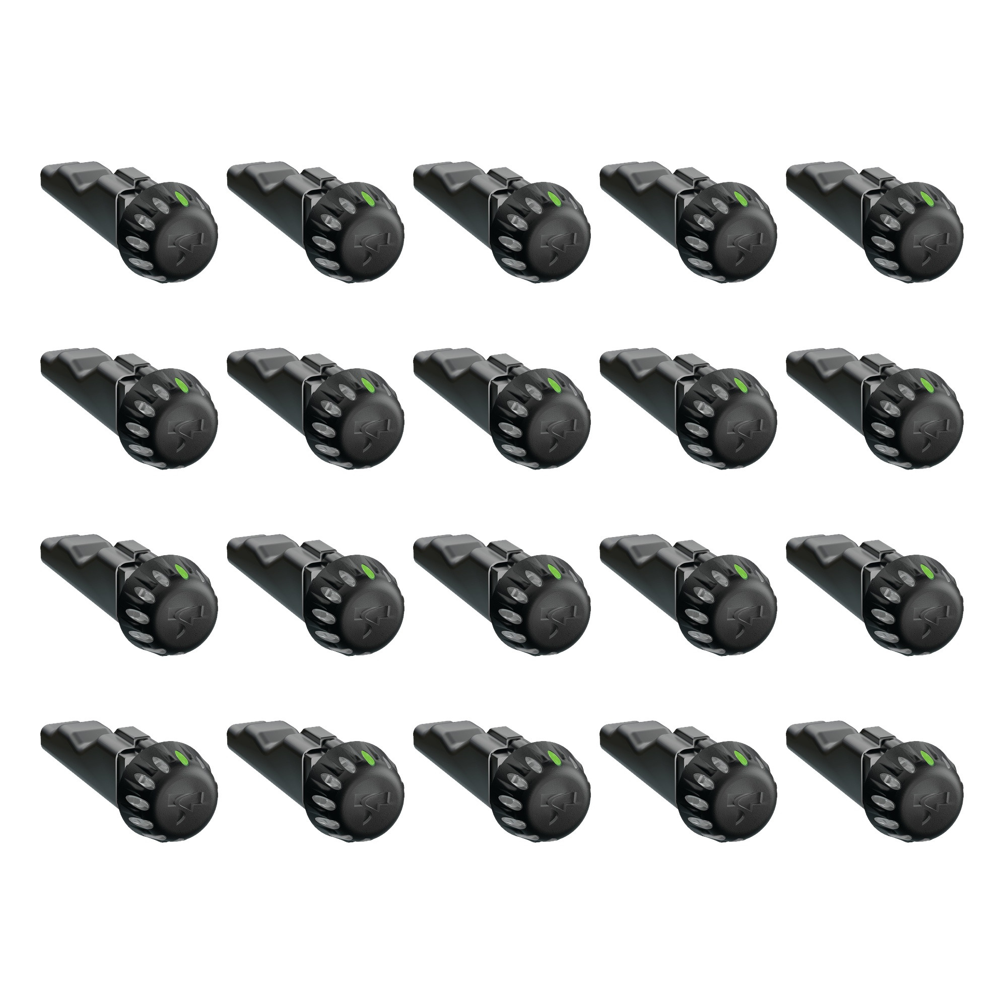
Tekonsha (20-Pack) Voyager iD Trailer Brake Controller, Proportional, 1 to 3 AxlesTekonsha$3,358.80Out of Stock
View productOur in-house experts typically reply within one business day.

Tekonsha

Always the correct part
We know our products
Quality Products
Free Shipping!
Always the correct part
We know our products
Quality Products
Free Shipping!
Complete kit bundle containing all necessary components for your project. Professional-grade components designed for reliable performance and long-lasting durability.

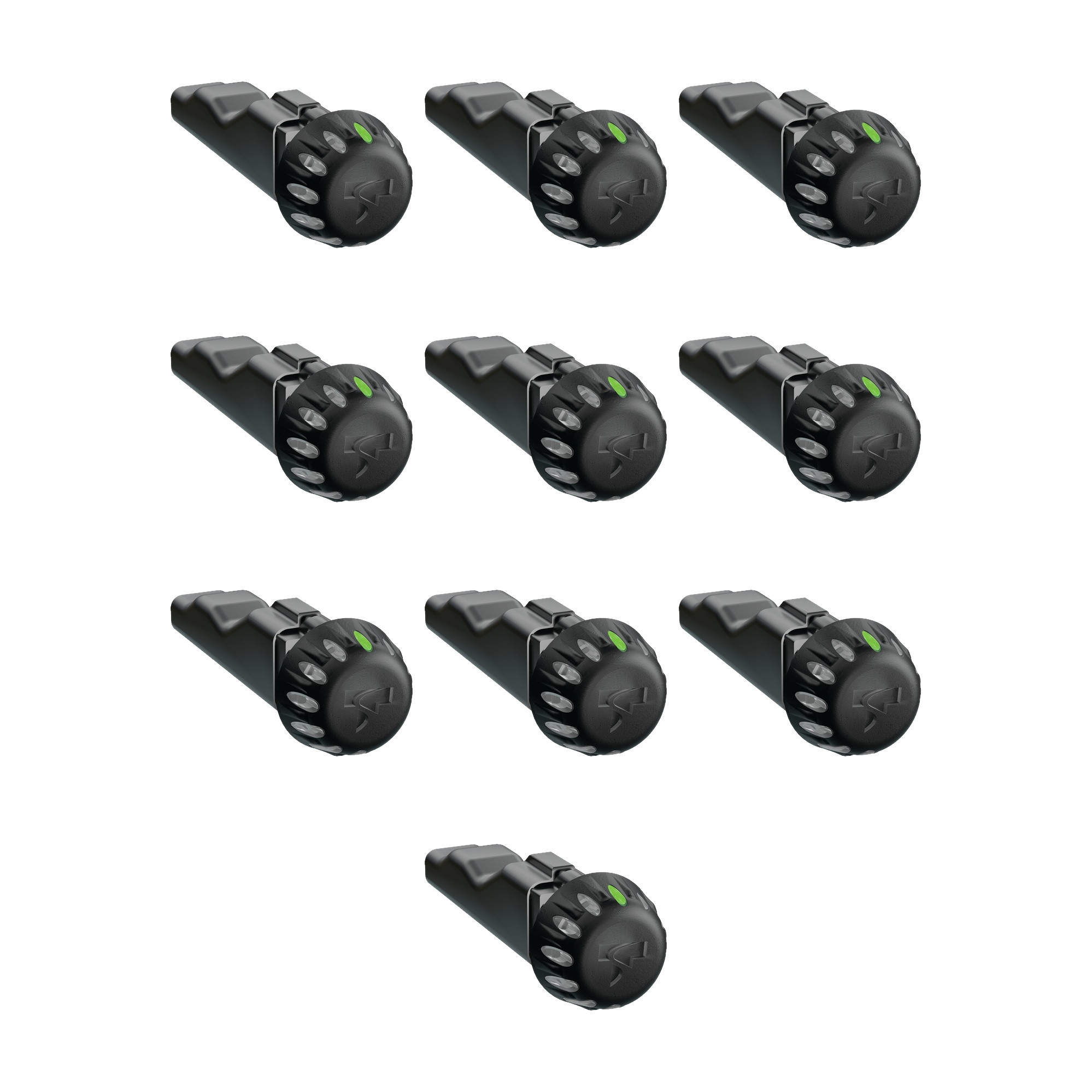
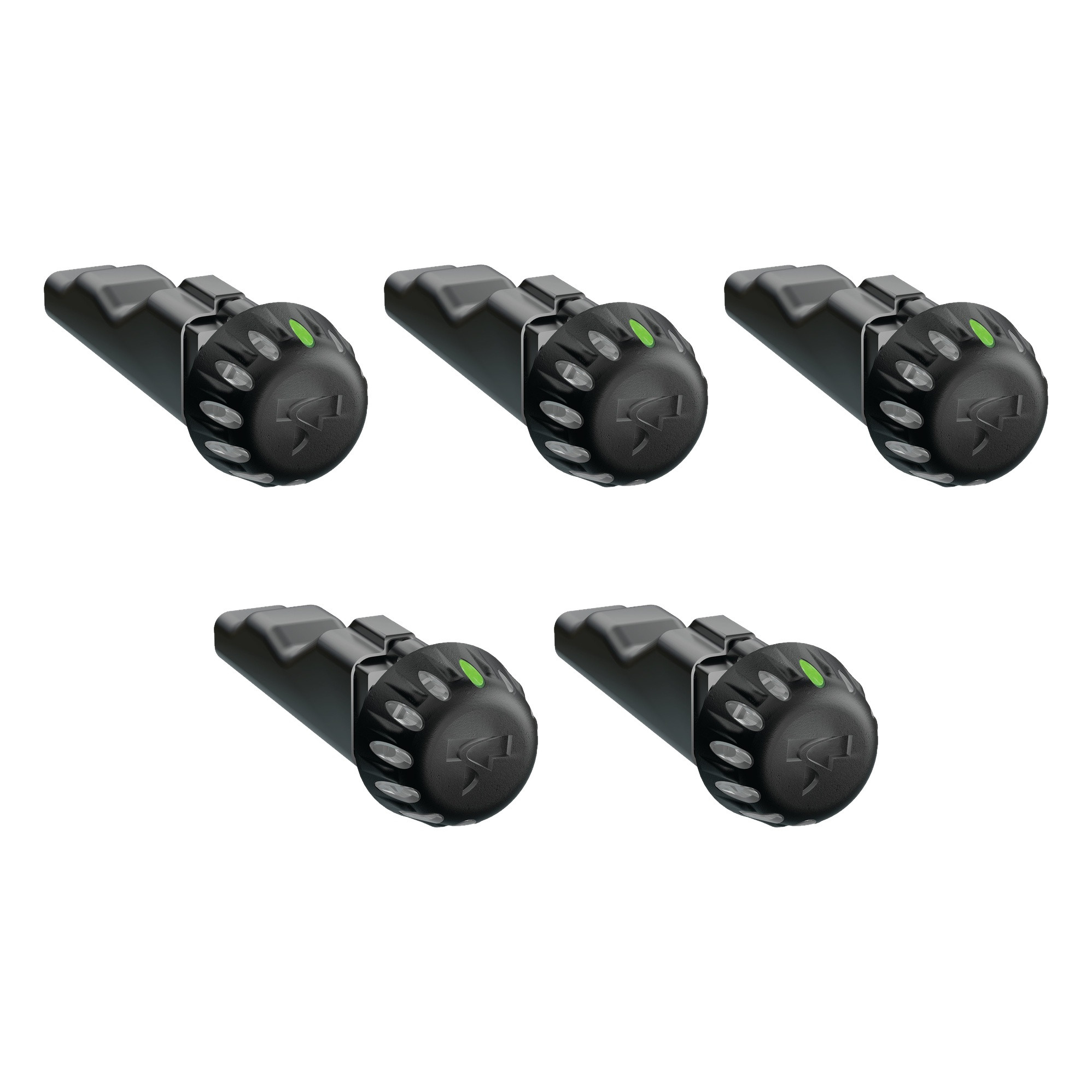
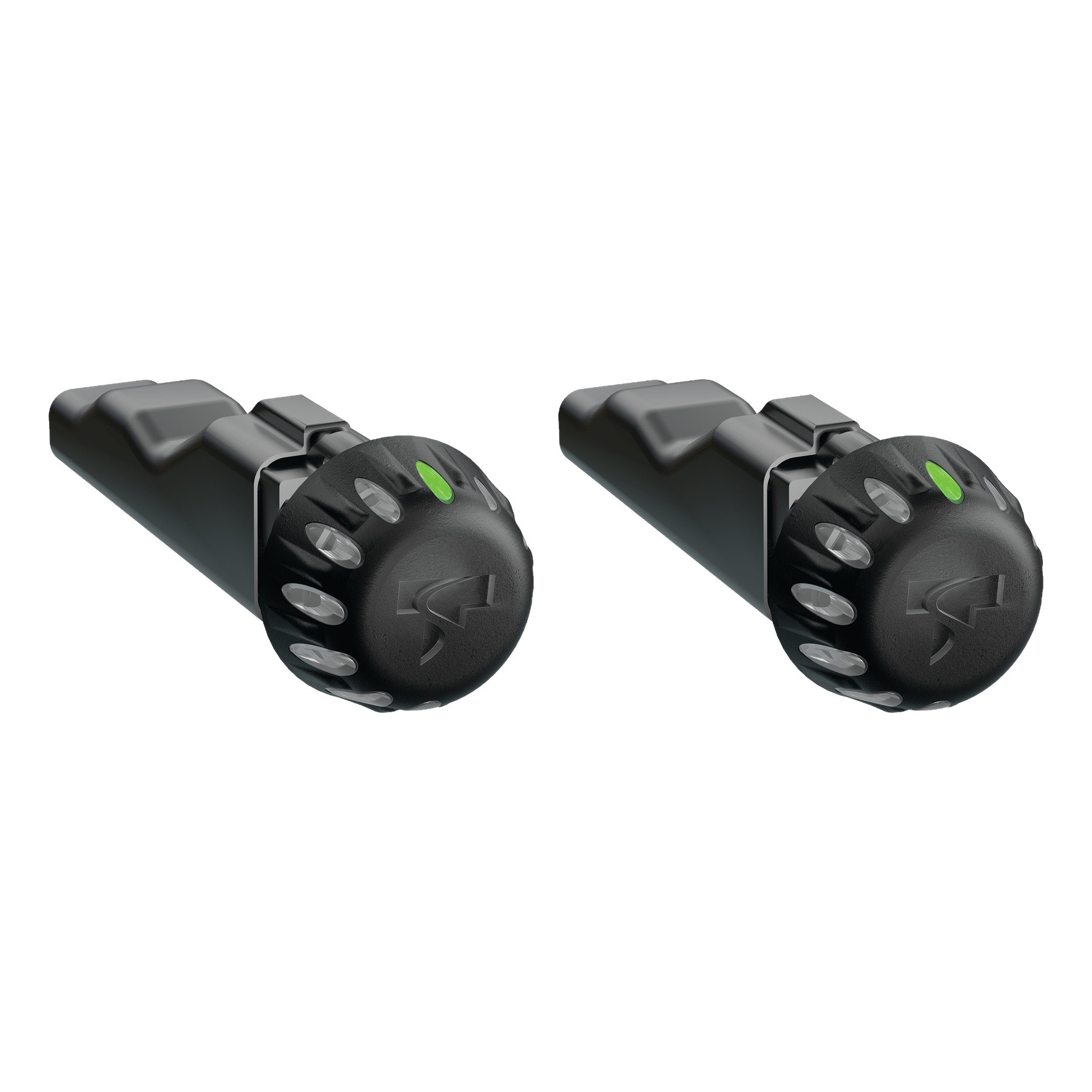
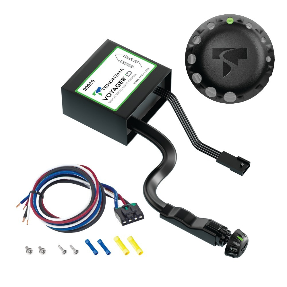
VOYAGER® Smart Braking with a sleek design. The Tekonsha Voyager iD trailer brake controller gives you dynamic braking power when you need it most. The Voyager iD brake controller seamlessly integrates control and display into your vehicle’s dash and out of the way from your knees or airbag systems. As one of the industry’s most advanced brake controller and a true proportional braking system, the iD provides a smooth braking response in any stopping situation. Wrapped in a sleek, OEM style design, this advanced electric brake controller knob that controls settings and trailer braking activity. Fingertip control of the lighted, rotary-style knob makes engaging manual override quick and easy too. The integrated in-dash appearance keeps your dashboard clean while the brains of this electric brake controller – otherwise known as the power module – are secured safely behind the dash, out of sight and safe from outside elements. The Voyager iD works with all trailers up to three axles and is backed by a limited lifetime warranty.
| BRAND: | TEKONSHA |
| PART NUMBER: | 90920 |
| WARRANTY: | LIMITED LIFETIME WARRANTY |
| WEIGHT: | 1.15 LBS |
| MATERIAL: | PLASTIC |
| BRAKE CONTROL TYPE: | TIMED |
| TRAILER BRAKE WHEEL QUANTITY: | UP TO SIX WHEELS |
| BRAKE TYPE: | ELECTRIC |
| DISPLAY TYPE: | DIGITAL OUTPUT |
| HYDRAULIC CONNECTIONS: | NO |
| SOLID STATE CONSTRUCTION: | YES |
| CIRCUIT BREAKER PROTECTED: | YES |
| HOUSING COLOR: | BLACK |
| BRACKET INCLUDED: | YES |


Keywords: TK90930-10PK bundle kit, complete kit, professional components, industrial kit, TK90930, Tekonsha

Tekonsha is a leading manufacturer of electronic trailer brake controllers, pioneering the category in the 1970s. The lineup spans proportional units such as the Prodigy P3 and Prodigy iD, time-delayed controllers, the wireless Prodigy RF, plus vehicle-specific wiring harnesses, adapters and trailer brake components engineered for smooth, predictable stopping at any speed.
Tekonsha Engineering Company began in 1964 building RV steps and mirrors. Within a few years it had found its real calling, and by the 1970s Tekonsha was pioneering the manufacture of electronic trailer brake controllers, the product category that still defines the brand. More than half a century later it remains the reference name in trailer braking and is part of the Horizon Global group alongside Reese, Draw-Tite, Fulton, Bulldog and Wesbar.
A brake controller is the component that tells a trailer's electric brakes how hard to work and when, and getting that right is the difference between a controlled stop and a shove from behind. Tekonsha builds both major types. Proportional controllers use an internal accelerometer to sense how quickly the tow vehicle is slowing and apply trailer braking to match, so light braking stays light and hard braking is immediate. Time-delayed controllers ramp to a preset output over a fixed interval, a simpler and more economical approach that suits occasional towing.
The current brake controller range covers most of that ground. The Prodigy iD pairs with a phone through Tekonsha's EDGE technology for setup and monitoring, the P3 offers storable settings for multiple trailers and a trilingual colour LED display, the Prodigy P2 adds a dimmable display and boost mode for heavier loads, and the Voyager keeps operation simple and dependable. The Prodigy RF mounts to the trailer itself and controls wirelessly, which suits rental fleets and drivers who swap tow vehicles.
Installation is supported by vehicle-specific brake control harnesses that plug into a factory connector rather than requiring cut-and-splice wiring, along with mounting brackets and adapters. Matched controller bundles pair a unit with the correct harness. Products are tested to meet and often exceed published industry standards.
Experts available to answer your questions
Call 888-634-9494Lifetime
The Voyager ID is a trailer brake control unit designed for 2, 4 and 6 brake applications. It works with all trailers equipped with 12V electric brakes and up to 3 axles. It allows you to control trailer braking from your tow vehicle using either the vehicle's brake pedal or a manual override button on the rotary knob control.
The Voyager ID is suitable for all trailers with 12V electric brakes and up to 3 axles. It requires a 12 volt negative ground system in your tow vehicle. If your vehicle has a factory tow package, a vehicle-specific plug-and-play harness may be available separately. Consult your vehicle manual or contact Horizon Global at 800-632-3290 for compatibility confirmation.
Required tools (not included): drill, 7/64" drill bit (for LED), 13/32" drill bit (for knob), center punch, safety glasses, wire cutters, crimp tool, voltage tester, and panel removal tools. For universal wiring installation, you will also need an automatic reset circuit breaker (20 amp for 1-2 axles, 30 amp for 3 axles), ring terminals, and butt connectors. If you lack these tools, stop and contact a professional installer.
Yes. You must drill two holes in the dash panel: a 7/64" hole for the LED indicator and a 13/32" hole for the Manual Knob Control Unit shaft. Before drilling, verify what is behind the surface to avoid damage to the vehicle or personal injury. Do not drill into exposed surfaces. The manual provides a drill hole guide to mark the hole centers.
The arrow on the label must point in the direction of travel. The front of the unit must be horizontal (±20 degrees). The unit must be parallel to the direction of travel (±20 degrees). The unit can be mounted at any rotation angle (0 to 360 degrees) as long as the arrow points in the direction of travel. It can be mounted out of sight under the dash.
Four wires must be connected: BLACK (positive battery) through a 20 or 30 amp automatic reset circuit breaker to the positive battery terminal; WHITE (negative battery) to a suitable ground location such as the negative battery terminal; RED (stoplight) to the cold side of the brake pedal stoplight switch; BLUE (brake output) to the trailer connector's brake wire. All four wires must be solidly connected or the brake control will not function properly.
Use a 20 amp automatic reset circuit breaker for 1-2 axle trailers, or a 30 amp automatic reset circuit breaker for 3 axle trailers. The circuit breaker connects the BLACK (positive battery) wire to the positive battery terminal.
Always warm the trailer brakes before setting the power output. Drive a short distance (0.4 km or ¼ mile) at about 70 KM/H (45 MPH) while pressing the manual override button with the power output control set to a low setting. This allows the trailer brakes to engage at a low level before you adjust the power setting.
Inspect and adjust your trailer brakes every 3000 miles or as use and performance requires. Brakes should be adjusted after the first 4,800 km (3,000 miles) of operation when the brake shoes and drums have 'seated', then at 320 km (200 mile) intervals, or as use and performance requires.
The package includes one Brake Control Unit, one set of installation and operation instructions, a Tekonsha Universal Brake Control Plug & Play Harness, a Manual Knob Control Unit with knob assembly, a mounting hardware kit, scissors, a drill hole guide, a nut, a foam pad, and a universal wire harness.
Yes. The Voyager ID can be mounted out of sight under the dash. It can be mounted at any rotation angle (0 to 360 degrees) as long as the arrow on the label points in the direction of travel. The front of the unit must remain horizontal (±20 degrees) and parallel to the direction of travel (±20 degrees).
Two mounting options are provided: Option 1 uses a bracket with a locking tab and supplied screw to attach the unit to a desired location. Option 2 uses a double-sided foam pad—remove tape from one side and firmly attach to the unit, then remove tape from the other side and attach to the mounting location. The unit must be securely mounted to a solid surface and not tied with cable wraps.
The knob control should be mounted in an accessible location to the driver at all times. It is designed to be mounted on or around the vehicle dash panel. Consider the location relative to the Brake Control Unit and verify harness routing before drilling any holes.
Clean the mounting location using a 50-50 mixture of rubbing alcohol and water. Before drilling any holes, test fit the units to ensure any removed panels can be reinstalled after installation. Use the provided drill hole guide to mark the surface for the centers of the control and LED holes. Measure the drill hole guide to ensure the box is scaled 1" x 1" before drilling.
Two drill bits are required: a 7/64" drill bit for the LED indicator hole (top hole), and a 13/32" drill bit for the Manual Knob Control Unit shaft hole (bottom hole). These bits are not included and must be obtained separately.
Before drilling, verify what is behind any surface to avoid damage to the vehicle and personal injury. Do not drill into any exposed surfaces. Ensure the area behind the dash panel is clear before drilling or mounting the bracket with screw. Use the provided drill hole guide to mark hole centers accurately.
After drilling the two holes (7/64" for LED, 13/32" for shaft), install the Manual Knob Control Unit LED and shaft post from the rear side through the dash panel holes. Install the nut and tighten securely, but do not overtighten. Rotate the shaft clockwise until it stops, then install the knob on the shaft, aligning the largest LED indicator position.
Using the bracket or double-sided foam pad provided, secure the Brake Control Unit to your chosen mounting location. The unit must be securely mounted to a solid surface. Do not use cable ties or wraps. Ensure the arrow on the label points in the direction of travel and the unit is horizontal (±20 degrees) and parallel to the direction of travel (±20 degrees).
Plug & Play installation is available if your vehicle has a factory tow package with brake control function wires and a connector under the dash. A vehicle-specific plug-and-play harness (purchased separately) connects directly to the factory harness and the brake control. Universal installation requires manual wiring of four wires (BLACK, WHITE, RED, BLUE) using soldering or crimp connectors, an automatic reset circuit breaker, ring terminals, and butt connectors.
The BLACK wire is the positive battery power supply line to the brake control. It must be connected through an automatic reset circuit breaker (20 amp for 1-2 axles, 30 amp for 3 axles) to the positive (+) terminal of the battery. This wire provides power to the entire brake control system.
The WHITE wire is the negative battery ground connection. It must be connected to a suitable ground location. The negative terminal of the battery is a suitable ground location in the absence of a trailer tow package connection. Inadequate grounding may cause intermittent braking or insufficient voltage to trailer brakes and may result in accidents.
The RED wire is the stoplight signal wire. It must be connected to the cold side of the brake pedal stoplight switch. Splice the wire down line from the switch; do not disturb the position of the switch. Do not disrupt the vehicle braking circuit. If unsure which wire to use, contact your vehicle dealer, a Tekonsha dealer, or technical support.
The BLUE wire is the brake output wire. It must be connected to the trailer connector's brake wire. This wire carries the brake signal from the control unit to the trailer brakes.
Reversing the BLACK and WHITE wires will damage or destroy the brake control. The BLACK wire must connect to the positive battery terminal through a circuit breaker, and the WHITE wire must connect to a suitable ground location. Always verify wire connections before powering the system.
Route all wires as far from the radio antenna as possible to reduce AM interference. Secure loose wires after making all connections. The manual recommends soldering connections or using crimp-on butt connectors. Proper wire gauge is critical; smaller gauge wire may result in less efficient braking.
Collection of water inside the trailer connector mounted on the tow vehicle will reduce the life of the connector. Take precautions to keep the connector dry, such as using protective covers or ensuring proper drainage.
Install the nut and tighten securely, but do not overtighten. The manual does not specify a torque value; use hand-tightening pressure sufficient to secure the unit firmly without stripping the threads.
The LED indicator shows the status of the brake control: Off = trailer not connected, unit asleep, or no power; Green = unit awake and trailer connected; Red = trailer brakes are applied (by brake pedal or manual override button); Flashing Red = potential issue that may prevent the brake control from functioning as intended.
The Manual Override button is located on the rotary knob and applies only the trailer brakes. It should be used in situations when you want to reduce speed slowly. When pressed, the output voltage ramps up power to the trailer brakes to the maximum power set by the user in about ½ second.
The Power Output control is located on the rotary knob and establishes the maximum amount of power available to the trailer brakes. As you rotate it from minimum (−) to maximum (+), more power becomes available to the brakes when the brake pedal is pressed or the manual override button is used. Adjust it when trailer load changes, different trailers are used, or road conditions change.
1. Warm the trailer brakes by driving 0.4 km (¼ mile) at 70 KM/H (45 MPH) with the manual override button pressed and power set low. 2. Starting with power at the lowest position (all the way left), roll forward slowly and stop. If no trailer braking is felt, increase power slightly by turning right. Repeat until you feel firm braking. If brakes lock up or jerk, lower power by turning left. 3. Test drive at 35 KM/H (20 MPH) and make several stops, adjusting power until stops are smooth and firm.
The power output should never be set high enough to cause trailer brakes to lock up. Skidding trailer wheels can cause loss of directional stability of both the trailer and tow vehicle, creating a dangerous driving condition.
Not all trailer brakes will lock up due to various conditions. If your trailer brakes will not lock up, it is important to determine the cause. This may involve inspecting the trailer brake system, checking brake adjustment, or consulting with a trailer service technician.
Brake pulsing can occur when the brake control is set too aggressively while towing with hazard flashers on. If such settings are necessary, a pulse preventer can be installed to eliminate the pulsing effect.
After installation, check all connections to ensure they are secure, secure any loose wires, and reinstall panels. Then test the installation by connecting a trailer to your vehicle and following the setup procedure: warm the trailer brakes, adjust the power output control, and test drive at low speed to verify smooth and firm braking.
Test your brake control unit settings each time a trailer is attached to your vehicle. This ensures the system is functioning correctly and the power output is properly adjusted for the specific trailer and load conditions.
Brakes should be adjusted after the first 4,800 km (3,000 miles) of operation, then at 320 km (200 mile) intervals, or as use and performance requires. 1. Jack up the trailer on adequate capacity jack stands (follow trailer manufacturer's recommendations). 2. Remove the adjusting hole cover from the brake backing plate. 3. Using a screwdriver or adjusting tool, rotate the star wheel to expand brake shoes until the wheel is very difficult to turn. 4. Rotate the star wheel in the opposite direction until the wheel turns freely with slight lining drag. 5. Replace the cover and lower the wheel. 6. Repeat on all brakes. For drop spindle axles, use a modified adjusting tool with about an 80 degree angle.
Never lift or support your trailer on any part of the axle or suspension system. Before getting under the trailer, always block the trailer tires and use jack stands that are properly placed on firm ground and have sufficient capacity for your trailer. Do not lift or place supports on any part of the suspension system. Always follow your trailer manufacturer's recommendations for lifting and supporting the unit.
Yes. Check periodically that your Brake Control Unit, LED indicator, and Manual Knob Control Unit are securely mounted to your vehicle. Vibration and use can loosen fasteners over time, so regular inspection is important for safe operation.
The power output is likely set to minimum. Adjust the power output to a higher setting by turning the knob to the right. Start with a low setting and gradually increase until you feel firm trailer braking.
Three possible causes: 1. Power output is set to minimum—adjust to a higher setting. 2. RED (stoplight) wire is connected incorrectly—verify it is connected to the cold side of the brake pedal stoplight switch. 3. Bad connection on RED wire—check the connection for corrosion or loose terminals. 4. Blown stoplight fuse—check and replace the vehicle's stoplight fuse if necessary.
Four possible causes: 1. Trailer is not connected to vehicle—verify the trailer connector is fully seated. 2. Open circuit on brake line—check all brake line connections for breaks or loose terminals. 3. Ground connection is poor—verify the WHITE wire is solidly connected to a suitable ground location. 4. No power to unit through BLACK wire—check that the BLACK wire is connected through the circuit breaker to the positive battery terminal.
Three possible causes: 1. RED (stoplight) wire is connected incorrectly—verify it is connected to the cold side of the brake pedal stoplight switch, not to a powered circuit. 2. Breakaway system employed—if the trailer has a breakaway brake system, it may be activating. 3. BLACK and WHITE wires reversed—if reversed, the control is destroyed and must be replaced.
Two possible causes: 1. Short circuit from brake line to ground—check all brake line connections for shorts or damaged insulation. 2. BLACK and WHITE wires reversed—if reversed, the control is destroyed and must be replaced. Verify all wire connections are correct before operating the system.
Free Shipping
Ships free on all orders
 Authorized Dealer
FREE ShippingFREE SHIPPING
Estimated delivery Mon, Nov 23 - Thu, Nov 26
Order before 2 PM EST Monday–Friday for same-day processing
Guaranteed safe & secure checkout
No reviews have been added for this product.