

Tekonsha Taillight Converter with Integrated Circuit ProtectionTekonsha$58.70Out of Stock
View productOur in-house experts typically reply within one business day.

Tekonsha

Always the correct part
We know our products
Quality Products
Free Shipping!
Always the correct part
We know our products
Quality Products
Free Shipping!
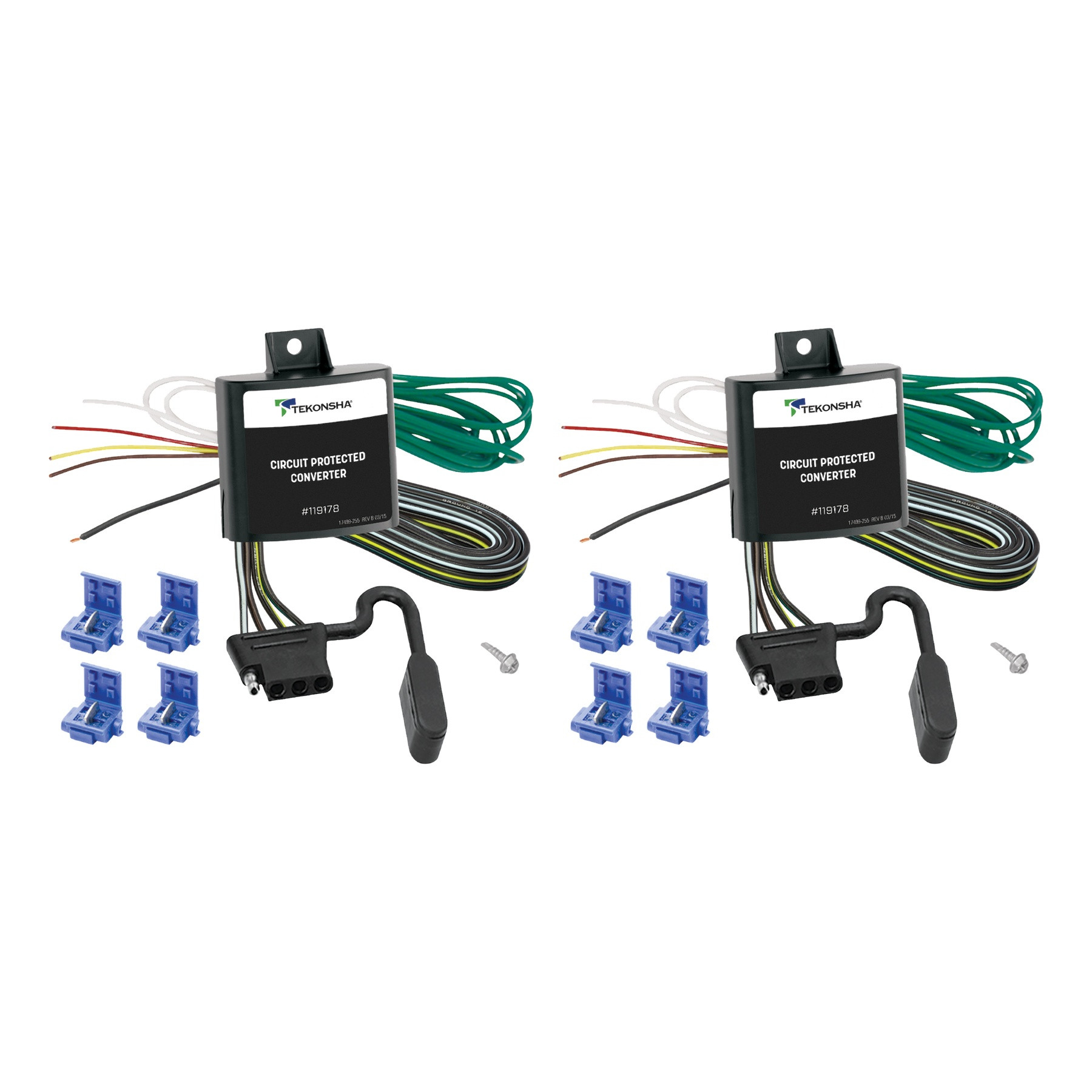
Complete kit bundle containing all necessary components for your project. Professional-grade components designed for reliable performance and long-lasting durability.

| BRAND: | TEKONSHA |
| PART NUMBER: | 119178 |
| WARRANTY: | LIMITED 1 YEAR WARRANTY |
| WEIGHT: | 0.65 LBS |
Keywords: TK119178-2PK bundle kit, complete kit, professional components, industrial kit, TK119178, Tekonsha

Tekonsha is a leading manufacturer of electronic trailer brake controllers, pioneering the category in the 1970s. The lineup spans proportional units such as the Prodigy P3 and Prodigy iD, time-delayed controllers, the wireless Prodigy RF, plus vehicle-specific wiring harnesses, adapters and trailer brake components engineered for smooth, predictable stopping at any speed.
Tekonsha Engineering Company began in 1964 building RV steps and mirrors. Within a few years it had found its real calling, and by the 1970s Tekonsha was pioneering the manufacture of electronic trailer brake controllers, the product category that still defines the brand. More than half a century later it remains the reference name in trailer braking and is part of the Horizon Global group alongside Reese, Draw-Tite, Fulton, Bulldog and Wesbar.
A brake controller is the component that tells a trailer's electric brakes how hard to work and when, and getting that right is the difference between a controlled stop and a shove from behind. Tekonsha builds both major types. Proportional controllers use an internal accelerometer to sense how quickly the tow vehicle is slowing and apply trailer braking to match, so light braking stays light and hard braking is immediate. Time-delayed controllers ramp to a preset output over a fixed interval, a simpler and more economical approach that suits occasional towing.
The current brake controller range covers most of that ground. The Prodigy iD pairs with a phone through Tekonsha's EDGE technology for setup and monitoring, the P3 offers storable settings for multiple trailers and a trilingual colour LED display, the Prodigy P2 adds a dimmable display and boost mode for heavier loads, and the Voyager keeps operation simple and dependable. The Prodigy RF mounts to the trailer itself and controls wirelessly, which suits rental fleets and drivers who swap tow vehicles.
Installation is supported by vehicle-specific brake control harnesses that plug into a factory connector rather than requiring cut-and-splice wiring, along with mounting brackets and adapters. Matched controller bundles pair a unit with the correct harness. Products are tested to meet and often exceed published industry standards.
Experts available to answer your questions
Call 888-634-94941 Year
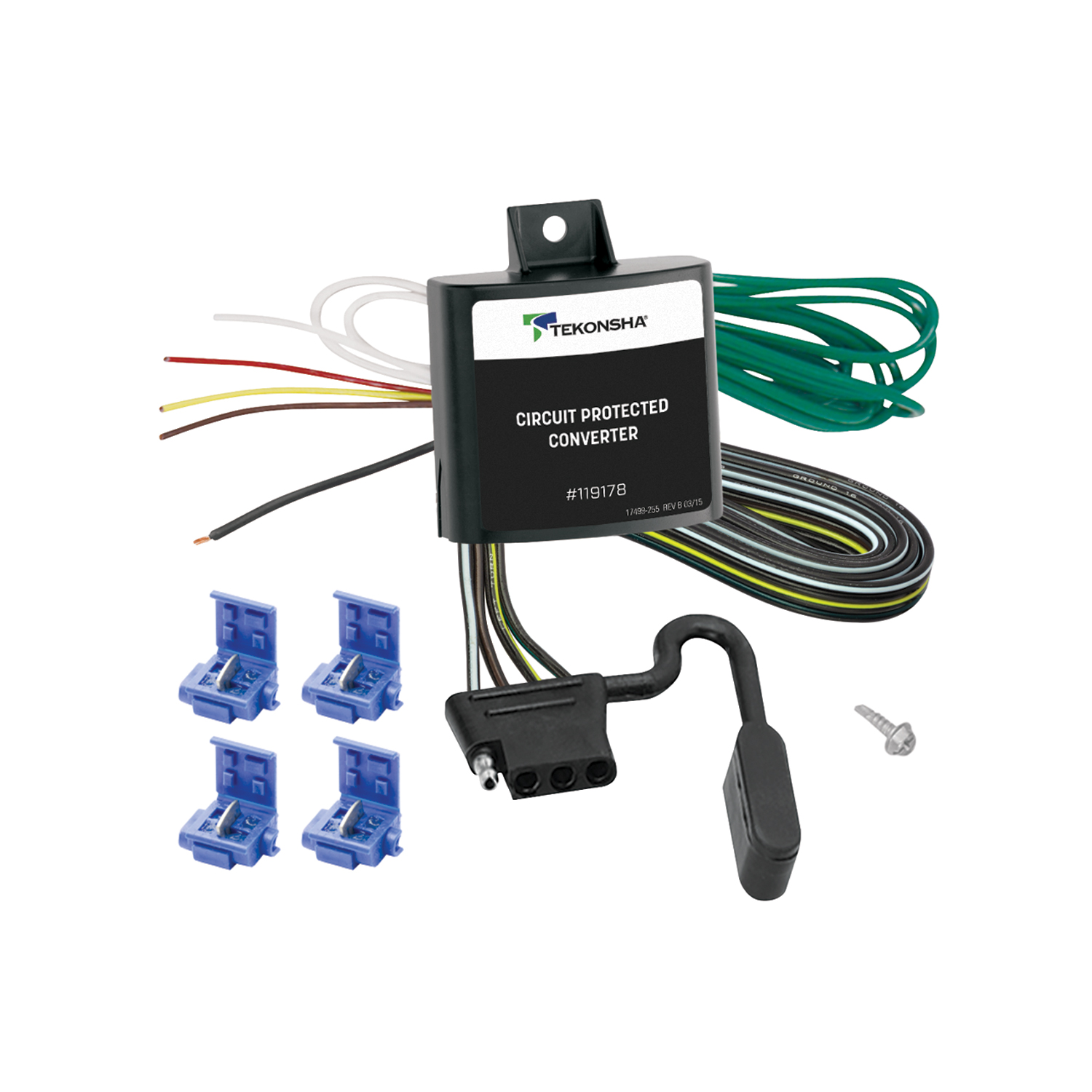
The Circuit Protected Converter is designed for 12 volt negative ground tow vehicles with separate turn/stop lights and no factory wiring harness. It is not compatible with vehicles that have combined turn/stop lights or existing factory trailer wiring harnesses. Check your vehicle's electrical system to confirm it is 12 volt negative ground before purchasing.
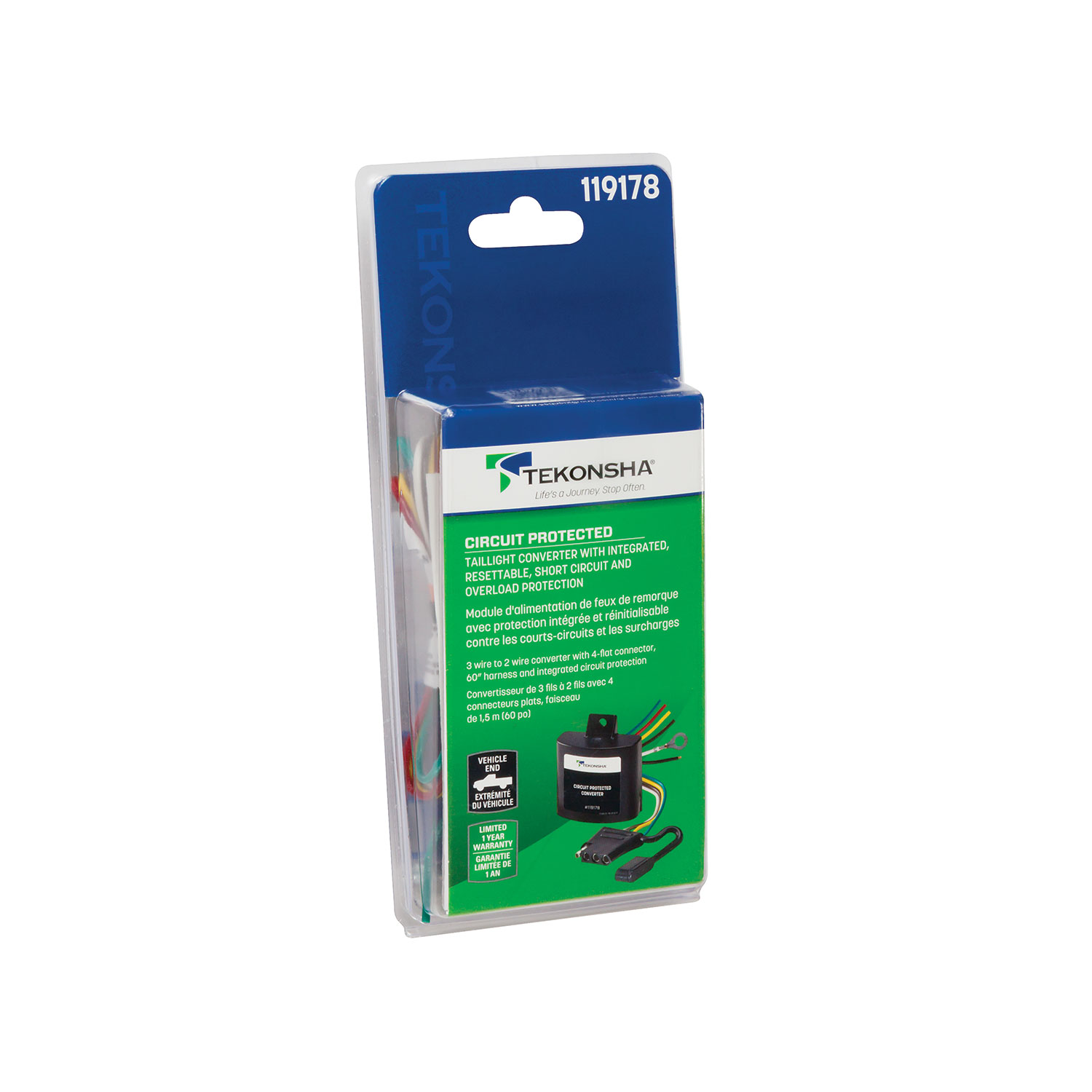
The Circuit Protected Converter is a device that connects your tow vehicle's tail lights and turn signals to a trailer's electrical system. It converts the vehicle's lighting signals (left turn, right turn, stop, and tail lights) into the appropriate signals for a trailer connector. It includes circuit protection to prevent overloads that could cause fires.
You will need: a drill with a 3/32" drill bit, wire crimpers, a Phillips head screwdriver, and a test probe (or circuit tester). A test light or trailer is also required to verify the installation after completion.
Yes. You must disconnect and isolate the vehicle's negative (-) battery terminal before wiring the power supply. Read and follow all warnings and cautions printed on the tow vehicle's battery before disconnecting it.
Mount the converter in an out-of-the-way spot near the left tail light, either in the trunk or on the frame rail if mounted under the vehicle. The converter must be mounted so that the wiring is directed downward. If directing wiring downward is impossible, direct it to the side instead.
Yes, a drill with a 3/32" drill bit is required to locate a suitable grounding point. Before drilling, verify what is behind any surface to avoid damage to the vehicle or personal injury. Do not drill into any exposed surfaces.
The converter uses the following wire colors: green wire, red wire, yellow wire, brown wire, and white wire. These connect to the vehicle's 12 volt battery, tail lights, and harness. Use blue wire taps for connections. The white wire must be grounded securely to the tow vehicle chassis or existing ground stud.
Attach the trailer wiring to the vehicle using splice connectors as shown in the installation illustration. Use blue wire taps for the connections. After all connections are made, secure all loose wires with cable ties.
With the ground wire connected and all other circuits attached, attach the ground lead of a circuit tester to the exposed ground terminal of the 4-flat connector end. Activate the tow vehicle's left turn, right turn, tail, and stop lights one at a time. Probe the three receptacles of the 4-flat end to confirm proper functions. All connections must be complete to function properly. Test and verify installation with a test light or trailer once installed.
Do not exceed the lower of your towing manufacturer's rating or these limits: maximum stop/turn light is 1 per side (2.1 amps), and maximum tail lights is 7.5 amps. Overloading the circuit can cause fires. Read your vehicle's owner's manual and instruction sheet for additional information.
Wear safety glasses during installation. Do not probe across two wires or between a wire and the vehicle structure, as this can damage electronic components. Before drilling, verify what is behind any surface to avoid damage to the vehicle or personal injury. Do not drill into exposed surfaces. Read and follow all warnings and cautions printed on the tow vehicle's battery.
Reconnect the tow vehicle's negative (-) battery cable after you have located a suitable grounding point and before you begin the testing procedure. This is step 7 in the installation sequence.
The white wire is the ground wire. It must be grounded securely to the tow vehicle chassis or an existing ground stud. This connection is essential for the converter to function properly.
Blue wire taps are splice connectors used to attach the trailer wiring to the vehicle's electrical system. The manual specifies that blue wire taps must be used for all connections in this installation.
Use a circuit tester to carefully probe one wire at a time to determine each vehicle function. The manual illustration shows which functions correspond to left turn, right turn, stop, and tail lights. Do not probe across two wires or between a wire and the vehicle structure, as this can damage electronic components.
The converter works with 12 volt negative ground tow vehicles that have separate turn/stop lights and no factory wiring harness. Check your vehicle's electrical system before purchasing.
Drill with 3/32" bit, wire crimpers, Phillips screwdriver, and test probe. You'll also need a test light or trailer to verify installation.
Yes, disconnect and isolate the negative battery terminal before wiring. Reconnect it after locating the grounding point, before testing.
Yes, you need to drill a hole for the grounding point using a 3/32" drill bit. Verify what is behind the surface before drilling to avoid damage.
Maximum 1 stop/turn light per side (2.1 amps) and maximum tail lights (7.5 amps). Do not exceed your vehicle manufacturer's towing rating.
Use a circuit tester to probe the 4-flat connector receptacles while activating each light function (left turn, right turn, tail, stop). Test with a test light or trailer to verify all functions work.
Verify that all connections are complete and properly made. The manual states that all connections must be complete to function properly. Use a circuit tester to probe each of the three receptacles of the 4-flat connector end while activating the corresponding light functions (left turn, right turn, tail, stop) to identify which connections are faulty. Ensure the ground wire is securely connected to the vehicle chassis or ground stud.
Use a circuit tester to probe the three receptacles of the 4-flat connector end one at a time while activating each light function (left turn, right turn, tail, stop). If a receptacle does not show the correct function, the corresponding wire connection may be loose, incorrectly spliced, or connected to the wrong vehicle wire. Verify each wire connection matches the correct vehicle function using the installation illustration.
Free Shipping
Ships free on all orders
 Authorized Dealer


FREE ShippingFREE SHIPPING
Estimated delivery Mon, Sep 28 - Thu, Oct 1
Order before 2 PM EST Monday–Friday for same-day processing
Guaranteed safe & secure checkout
No reviews have been added for this product.