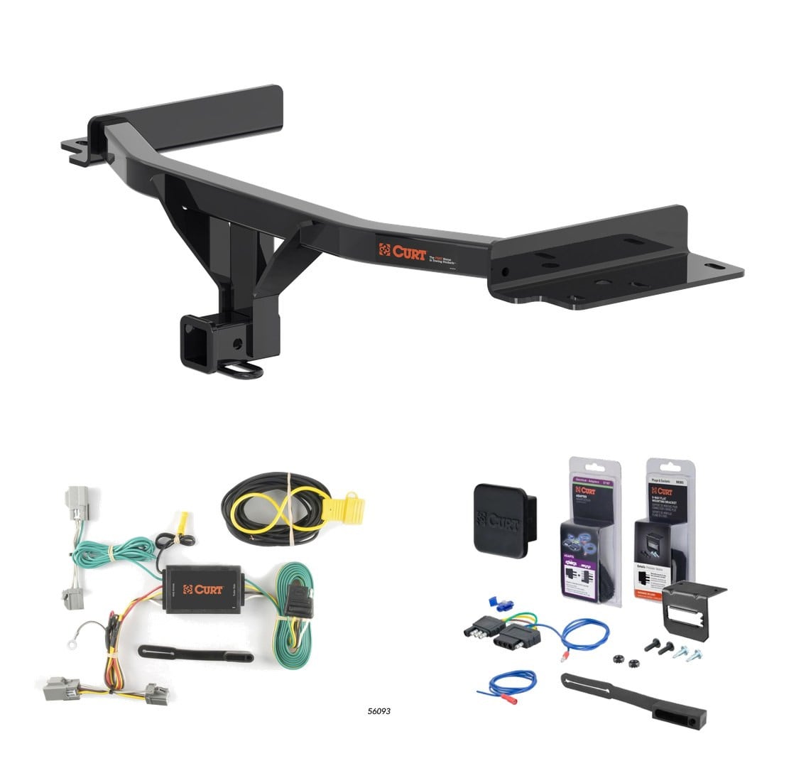
2025 - 2026 Ford Explorer Curt 2" Class 3 Trailer Tow Hitch + 5-Flat Wiring Kit Tow Boat/Utility Trailer with Surge Brakes 13438CURTOriginal price was $462.75. Current price is $374.75.In Stock
View productOur in-house experts typically reply within one business day.

CURT
Verify Fitment
Select your vehicle to confirm this part fits.
2020 - 2024 Lincoln Aviator
Confirmed to Fit






Always the correct part
We know our products
Quality Products
Free Shipping!
Always the correct part
We know our products
Quality Products
Free Shipping!
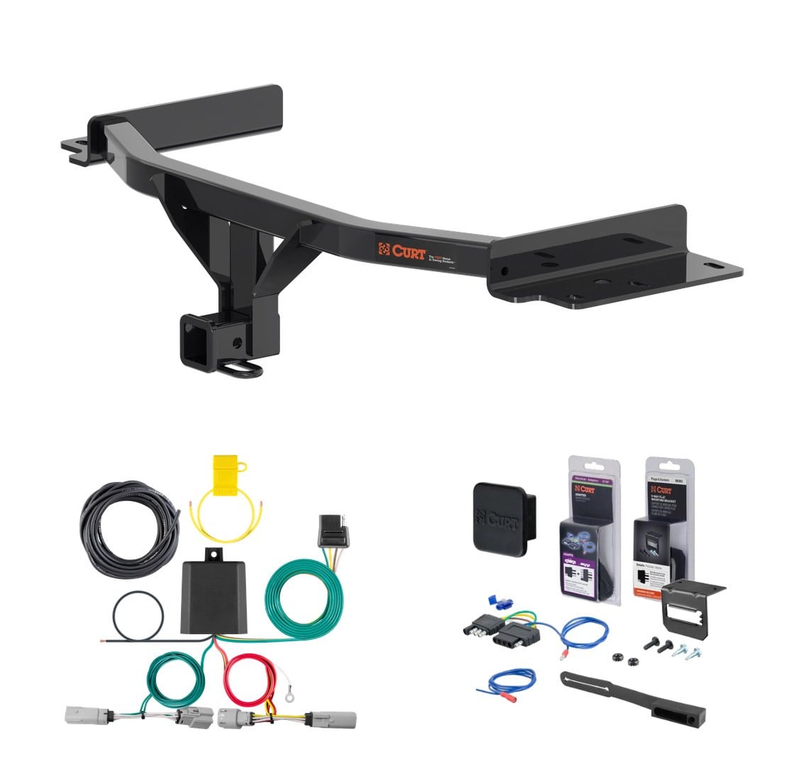
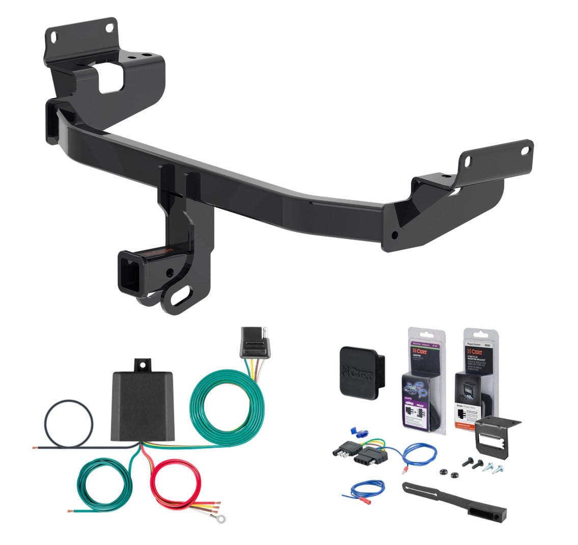
Complete CURT Class 3 2" trailer hitch and 5-flat wiring kit (with 4-way to 5-way adapter for surge brakes) engineered for the 2025 - 2026 Lincoln Aviator. Vehicle-specific fit, plug-and-play installation, all hardware and instructions included.
This custom kit fits the following vehicles:
All Hardware and Installation Instructions Included!
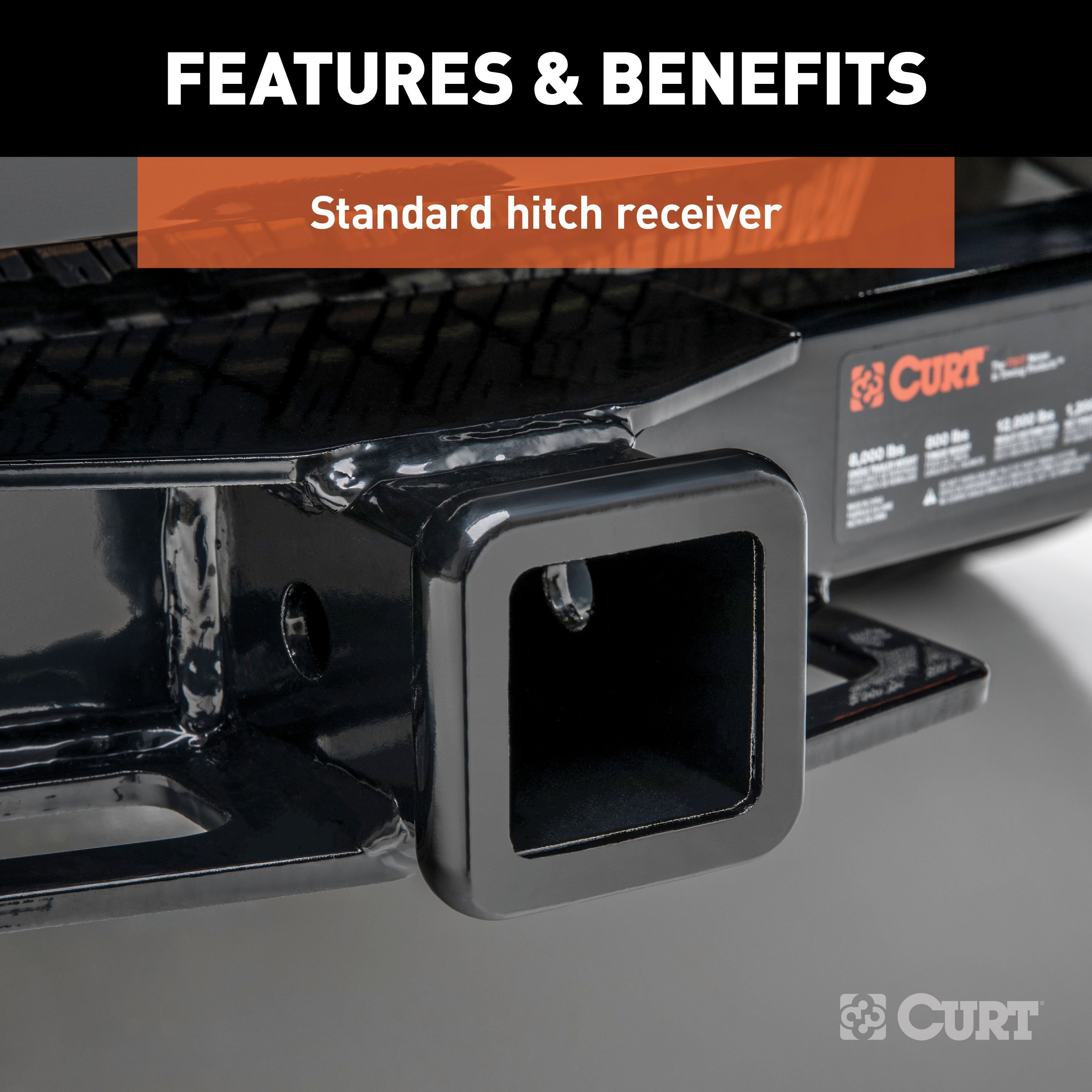
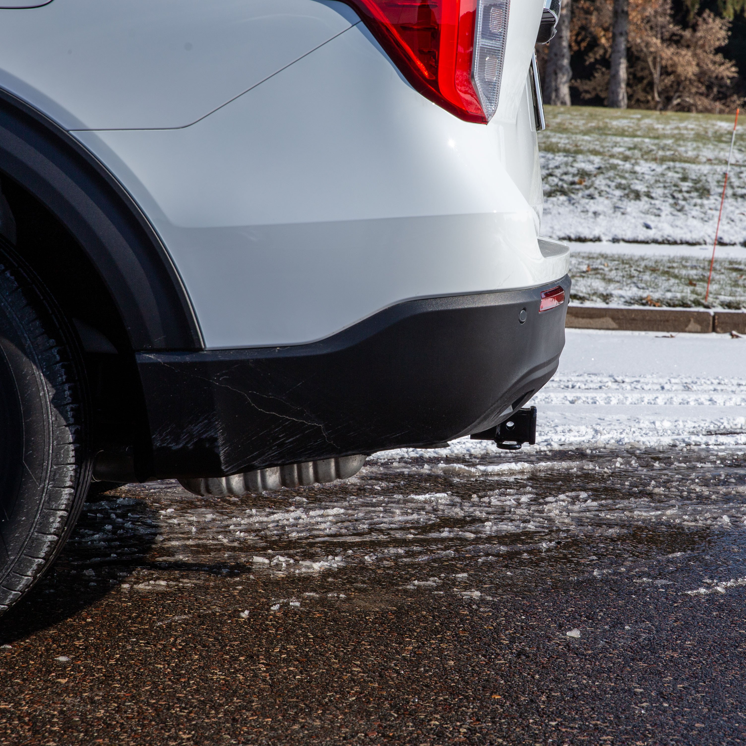
Whatever your task at hand -- whether it's launching that boat before daybreak, setting up your camper before the rush or getting a final load to the dump before close -- CURT class 3 trailer hitches offer the strength needed for serious towing. They make it easy to hitch up and Bring It, offering a vehicle-specific fit and the weight capacity to handle a variety of trailers. Custom class 3 hitches are the most common type of receiver hitch for pickup trucks and SUVs. Because of their weight range, they are also found on full-size cars, crossovers and minivans. Each custom-fit class 3 hitch package is made for vehicle-specific mounting. This particular kit fits certain years of the Ford Explorer and Lincoln Aviator (see application info to verify vehicle compatibility). It provides a weight carrying capacity of 6,000 lbs. GTW and 600 lbs. TW. CURT class 3 trailer hitches are typically used to attach and haul utility trailers, boat trailers, campers, snowmobile or ATV haulers and more (NOTE: Never exceed the lowest-rated towing component). Each class 3 hitch has a 2" receiver tube and is tested in accordance with SAE J684 for safety. To ensure that CURT class 3 receiver hitches have what it takes for serious trailering, they are designed using a hands-on approach and are constructed with rugged, high-strength steel and precise welding. We also protect our class 3 hitches in a co-cured finish of liquid A-coat and black powder coat for superior resistance to rust, chipping and UV damage.
If your vehicle is not equipped with wiring for towing a trailer, CURT custom wiring is the ideal solution. A custom wiring harness -- also called a T-connector -- is a simple, plug-and-play electrical device that plugs into your automotive electric system and provides a standard, universal trailer wiring connection. This is done using two or more vehicle-specific, OEM-compatible connectors to plug into the taillight assembly, eliminating the need for cutting, splicing and soldering during installation. Custom wiring harnesses are made vehicle-specific, and while they are not available for all vehicles, they do offer one of the fastest, easiest and most secure ways to wire a vehicle for towing. This particular plug-in harness provides a 4-way flat connector socket and is designed to be a custom wiring harness to fit certain years of the Lincoln Aviator (to verify your vehicle compatibility, see application info). It comes with all necessary wiring components to establish a reliable trailer wiring connection, as well as a dust cover to keep the connector clean when not in use. You have a picture in mind of your next destination -- maybe it's the boat landing at your favorite fishing spot, maybe it's a campsite that overlooks one of nature's masterpieces, or maybe it's the next big jobsite. However, turning that picture into a reality takes more than just daydreaming. It takes a solid connection and the right amount of power. CURT custom wiring is made with some of the most sophisticated technology in the industry and is designed to install with ease, giving you a long-lasting electrical connection for your towing hitch setup.

CURT offers a variety of high-quality trailer hitches and accessories for select vehicle models. Find the perfect fit for your towing needs at TowUniverse.
CURT, a Lippert brand, offers a complete line of towing products and is the leading manufacturer of custom-fit trailer hitches. We offer the broadest selection of custom-fit hitches, and each one is designed, welded, and coated in Wisconsin.
CURT is also a leader in flat towing products, as well as 5th wheel, gooseneck, and weight distribution hitches, ball mounts, electrical components, cargo solutions, and other towing accessories.
For everything from passenger cars and vans to full-size pickups and SUVs, CURT is 'The First Name in Towing Products®.'

Experts available to answer your questions
Call 888-634-94941 compatible vehicles
| Year | Make & Model | Notes |
|---|---|---|
| 2020 - 2024 | Lincoln Aviator | — |
The 20 - 24 Lincoln Aviator Curt 2" Class 3 Trailer Tow Hitch + 5-Flat Wiring Kit Tow Boat/Utility Trailer with Surge Brakes 13438 (Part #5W-CHW-2180) fits 2020-2024 Lincoln Aviator models. The 2024 model year is the last year covered by this part number. For newer models, check for an updated version.
Yes, the 20 - 24 Lincoln Aviator Curt 2" Class 3 Trailer Tow Hitch + 5-Flat Wiring Kit Tow Boat/Utility Trailer with Surge Brakes 13438 (Part #5W-CHW-2180) is designed to fit the 2020-2024 Lincoln Aviator.
The 20 - 24 Lincoln Aviator Curt 2" Class 3 Trailer Tow Hitch + 5-Flat Wiring Kit Tow Boat/Utility Trailer with Surge Brakes 13438 (Part #5W-CHW-2180) fits the following vehicles: 2020-2024 Lincoln Aviator. Always verify your specific year, make, and model before ordering.
The 20 - 24 Lincoln Aviator Curt 2" Class 3 Trailer Tow Hitch + 5-Flat Wiring Kit Tow Boat/Utility Trailer with Surge Brakes 13438 (Part #5W-CHW-2180) Refer to the included instructions for installation details. Basic hand tools are typically all you need.
Yes, CURT part number 13438 is designed for 2020-present Ford Explorer and Lincoln Aviator SUVs. Confirm your vehicle year and model match this range before purchasing.
Yes, CURT part number 13438 is designed for 2020-present Lincoln Aviator and Ford Explorer SUVs. Confirm your vehicle year and model match this range before purchasing.
The CURT 13438 is rated for a maximum of 6,000 lbs trailer weight and 600 lbs tongue weight when used as a weight-carrying hitch. You must never exceed your vehicle manufacturer's recommended towing capacity, which may be lower than the hitch rating.
Required tools are: ratchet, torque wrench, 6" socket extension, 7mm/10mm/21mm sockets, aviation shears, power drill with 1/4" drill bit, marker, tape measure, safety glasses, and plastic rivet gun. Using proper tools will greatly improve installation quality and reduce installation time.
Two people may be required to ease installation. The manual recommends reading all instructions thoroughly before beginning and notes that using proper tools will greatly improve the quality of the install and reduce the time required.
No, the CURT 13438 requires no frame drilling. It uses fishwire hardware to route fasteners through existing access holes and mounting holes on the frame.
Yes, trimming is required. You must trim the rear fascia and wire track using aviation shears. The trim diagram shows approximate dimensions of 4.75" and 3.5". All dimensions are approximate, so you must confirm fit prior to trimming. You must also remove the heat shield and wheel well fasteners to access the installation area.
Yes, you must lower the exhaust by removing one fastener on the outside of each frame rail using a 10mm socket, and remove two exhaust isolator hangers using the Rubber Isolator Removal Diagram as reference. You must support the exhaust to avoid damage during this process.
If an underbody panel is present, you must remove it by removing eight fasteners using a 10mm socket and four plastic fasteners. Set the panel aside for reinstallation after the hitch is installed.
Remove the M16 bumper bolt in the frame on each side using a 21mm socket. Return these bolts to the vehicle owner—they are not part of the hitch installation.
Fishwire two 1/2" carriage bolts and two CM-SP6 spacers into the access hole and out the mounting holes on each side. Do not reinstall the rearward most frame rail nut. Reinstall the trimmed heat shield after fishwiring the hardware.
Torque the 1/2" hardware to 75 ft-lbs. This is applied after raising the hitch into position.
Torque the M16 hardware to 146 ft-lbs. This is applied after raising the hitch into position.
Reinstall vehicle components using steps 1–5 in reverse order. This means reinstalling the M16 bumper bolts, wheel well fasteners and heat shield, exhaust isolator hangers and exhaust fasteners, and finally the underbody panel if it was present.
If a kick sensor is present, remove four of the six rivets using a drill along the rear fascia, starting from the driver side, to avoid damaging the kick sensor while trimming. Replacement rivets are included in the hardware kit. When raising the hitch into position, it will be positioned between the upper and lower kick sensor wires.
Safety glasses must be worn at all times while installing this product.
All non-trailer loads applied to this product must be supported by CURT 18050 stabilizing straps. Failure to properly support non-trailer loads will void the product warranty.
Periodically check the receiver hitch to ensure all fasteners are tight and all structural components are sound. This ongoing inspection helps maintain the integrity and safety of the installation.
The kit includes: four 1/2-13 UNC 1-1/4" grade 8 carriage bolts (10-10278), four serrated flange nuts 1/2-13 UNC grade 8 (20-00062), four 0.250 x 1.00 x 3.00" square hole spacers (CM-SP6), four 1/2" fishwire (1_2 FISHWIRE), four M6 black nylon rivets (10-10401), two M16x2 35mm class 10.9 hex cap screws (10-10403), and two M16 flat washers (30-00185).
When trimming the fascia and wire track using aviation shears, move the sensor wire out of the wire track to avoid cutting it. If a kick sensor is present, remove four of the six rivets using a drill along the rear fascia, starting from the driver side, before trimming to avoid damaging the kick sensor.
Yes, the CURT 13438 is designed for 2020-present Ford Explorer and Lincoln Aviator SUVs.
The CURT 13438 is rated for 6,000 lbs trailer weight and 600 lbs tongue weight. Never exceed your vehicle manufacturer's recommended towing capacity.
No, the CURT 13438 requires no frame drilling. It uses fishwire hardware through existing frame access holes.
Yes, you must trim the rear fascia and wire track using aviation shears. Approximate trim dimensions are 4.75" and 3.5", but you must confirm fit prior to trimming.
Required tools: ratchet, torque wrench, 6" socket extension, 7mm/10mm/21mm sockets, aviation shears, power drill with 1/4" drill bit, marker, tape measure, safety glasses, and plastic rivet gun.
Torque 1/2" hardware to 75 ft-lbs and M16 hardware to 146 ft-lbs.
All non-trailer loads must be supported by CURT 18050 stabilizing straps. Failure to properly support non-trailer loads voids the warranty.
Yes, you must lower the exhaust by removing one fastener on each side using a 10mm socket and remove two exhaust isolator hangers. Support the exhaust to avoid damage.
The Curt 56453 is a wiring converter system for SUVs and vans that converts factory taillight signals to a 4-flat trailer connector. It includes a powered converter module that processes left turn (yellow), right turn (green), brake (red), and taillight (brown) signals from the vehicle's existing taillights and routes them to a 4-flat connector for trailer use.
The Curt 56453 is designed for SUVs and vans with third-row seats and spare tire access in the cargo area. The manual does not specify which makes and model years are compatible. Contact Curt Manufacturing or consult a fitment database to confirm compatibility with your specific vehicle.
No. The converter system is designed only for 12-volt negative ground electrical systems. It cannot be used on positive ground vehicles.
Required tools are: ratchet, 7mm socket, socket extension, flathead screwdriver, panel trim removal tool, wire crimper, wire stripper, cutting tool, and electrical tape. Cable ties and double-sided tape are provided with the product.
The kit includes a black converter box, a 4-flat connector with dust cover, a white ground wire with ring terminal, yellow, green, brown and red signal wires, a black 12-gauge power wire with fuse holder (15-amp max), cable ties, double-sided tape, a screw for the ground connection, and a 15-amp fuse.
Yes. You must disconnect the negative battery terminal in the engine compartment on the driver side before beginning installation. Fasten this wire down and away from the battery while completing the installation. Reconnect it only after all other steps are complete and the fuse is installed.
Open the trunk and place third-row seats in the down position. Remove floor coverings to expose the spare tire. Remove trim covers from cargo tie-down points using a flathead screwdriver, then remove the cargo tie-downs using a 7mm socket. Remove the skid plate by releasing push fasteners with a panel trim removal tool and separating the hatch sensor connector. Remove side panel pockets using the panel trim removal tool.
The yellow wire (left turn signal) is routed from the converter box to the driver-side taillight housing. It is installed between the main harness and the taillight connector. The converter box itself is adhered to a flat spot inside the vehicle near the taillight where the yellow wire is routed, using the provided double-sided tape.
The green wire (right turn signal) is routed along the back of the vehicle from the driver side to the passenger side. It is installed between the main harness and the passenger-side taillight connector, following the same procedure as the yellow wire on the driver side.
Use a panel trim removal tool to loosen the sidewall panels and locate the taillight housing. Separate the existing connectors carefully, taking care not to damage the locking tabs. Install the signal wire (yellow on driver side, green on passenger side) between the main harness and the taillight. Ensure the connectors are fully inserted with locking tabs in place.
Drilling may be required for the ground wire connection. You must locate a suitable grounding point near the converter, such as an existing screw with nut in the vehicle frame. If no existing point is available, drill a 3/32-inch pilot hole for the provided screw. The area must be free of rust, dirt and paint. Always check for hidden items behind or under any surface before drilling to avoid damage and personal injury.
If a suitable existing grounding point is not available, drill a 3/32-inch pilot hole for the provided screw. The area should be free of rust, dirt and paint.
Signal circuits are rated at 5.0 amps per side. Tail and running circuits are rated at 7.5 amps total. Do not exceed the product rating or the tow vehicle lamp load rating, whichever is lower.
The battery connection must be fuse-protected with a 15-amp maximum fuse. A fuse holder with 15-amp fuse is provided. Install the fuse after all other installation steps are complete. Exceeding this rating can cause loss of warranty, overheating and potential fire.
The power wire is 12-gauge or larger. It is routed from the vehicle battery to the converter using butt connectors, as shown in the Powered Converter Lead Instruction Sheet.
Yellow = left turn signal; Green = right turn signal; Red = brake signal; Brown = taillight (running light). The white ground wire connects to the vehicle frame. The black power wire connects to the positive battery terminal.
Route the 12-gauge black power wire from the vehicle battery to the converter, taking care to avoid pinch points and hot or rotating components. When passing the power wire through sheet metal, use an existing grommet, add a grommet, or use silicone to protect the wire from sharp edges. Secure the power wire to the vehicle chassis using the provided cable ties.
Attach the ring terminal of the white ground wire to the vehicle body using the screw provided. Locate a suitable grounding point near the converter, such as an existing screw with nut in the vehicle frame, or drill a 3/32-inch pilot hole if necessary. The area must be free of rust, dirt and paint.
When not in use, roll up the 4-flat connector and store it in a convenient, out-of-the-way location. When in use, route it to the center of the vehicle. Secure any loose wires with the provided cable ties. Install the provided 4-flat dust cover to help prevent corrosion.
Do not exceed the product rating or the tow vehicle lamp load rating, whichever is lower. Exceeding the product rating can cause loss of warranty, overheating and potential fire.
Before drilling, check for miscellaneous items that may be hidden behind or under any surface to avoid damage and personal injury. This is especially important when drilling the 3/32-inch pilot hole for the ground wire connection.
Once the 12-volt power wire is connected to the harness, verify that the harness is functioning by attaching the battery and testing with a test light, 4-flat tester, or a functioning trailer. Do not install the fuse until all other steps are complete.
Periodic inspection of all wires and connections should be performed to ensure there is no visible damage or loose connections. Install the provided 4-flat dust cover to help prevent corrosion when the connector is not in use.
The Curt 56453 is designed for SUVs and vans with third-row seats and spare tire access. It requires a 12-volt negative ground electrical system. Confirm your specific vehicle make and model with Curt Manufacturing or a fitment database.
You need a ratchet, 7mm socket, socket extension, flathead screwdriver, panel trim removal tool, wire crimper, wire stripper, cutting tool, and electrical tape. Cable ties and double-sided tape are included.
Yes, disconnect the negative battery terminal before starting installation. Reconnect it only after all steps are complete and the 15-amp fuse is installed.
The battery connection must use a 15-amp maximum fuse. A fuse holder with 15-amp fuse is provided. Install the fuse after all other steps are complete.
Yellow = left turn, Green = right turn, Red = brake, Brown = taillight, White = ground, Black = power. The 12-gauge black power wire connects to the positive battery terminal.
After connecting the 12-volt power wire, test the harness with a test light, 4-flat tester, or functioning trailer before installing the fuse.
First, verify that the 15-amp fuse is installed in the fuse holder. Check that all wire connections are fully inserted with locking tabs in place at both the driver-side and passenger-side taillight connectors. Ensure the white ground wire ring terminal is securely attached to the vehicle frame and the black power wire is properly connected to the positive battery terminal. Test the system with a test light, 4-flat tester, or functioning trailer to identify which circuits are not working. Inspect all wires for visible damage or loose connections.
The yellow wire (left turn signal) may not be properly installed between the main harness and the driver-side taillight connector. Verify that the yellow wire is fully inserted and the connector locking tabs are in place. Check that the converter box is securely mounted with double-sided tape near the driver-side taillight. Inspect the yellow wire for visible damage. Test the circuit with a test light to confirm signal presence.
The green wire (right turn signal) may not be properly installed between the main harness and the passenger-side taillight connector. Verify that the green wire is fully inserted and the connector locking tabs are in place. Check that the green wire is properly routed along the back of the vehicle from the driver side to the passenger side without kinks or damage. Inspect the wire for visible damage and test the circuit with a test light.
The red brake wire may not be properly connected in the converter system. If the converter is being used as a powered module for a two-wire system, the red brake wire must be grounded. Verify that all connections at the taillight connectors are fully inserted with locking tabs in place. Check that the white ground wire is securely attached to the vehicle frame. Test the brake circuit with a test light.
The product rating or tow vehicle lamp load rating is being exceeded. Verify that the total electrical load does not exceed 5.0 amps per side for signal circuits or 7.5 amps total for tail and running circuits. Ensure the 15-amp fuse is the correct rating and is properly installed. Check that the battery connection is secure and there are no short circuits in the wiring. If the fuse continues to blow, discontinue use and contact the manufacturer.
On Sale Today
Original price was $493.75. Current price is $405.75.You save $88.00 (18%)
Free Shipping
Ships free on all orders
 Authorized Dealer


Quick Ship
In stock and ready to ship — order now!
FREE ShippingFREE SHIPPING
Estimated delivery Wed, Sep 16 - Sat, Sep 19
Order before 2 PM EST Monday–Friday for same-day processing
Guaranteed safe & secure checkout
No reviews have been added for this product.