2018-2021 Hyundai Kona Tekonsha Custom 7-Way + Brake Controller Install KitTekonshaOriginal price was $307.50. Current price is $290.78.Out of Stock
View productOur in-house experts typically reply within one business day.

Tekonsha
Verify Fitment
Select your vehicle to confirm this part fits.
2022 - 2023 Hyundai Kona
Confirmed to Fit


Always the correct part
We know our products
Quality Products
Free Shipping!
Always the correct part
We know our products
Quality Products
Free Shipping!
Free Shipping
Ships free on all orders
 Authorized Dealer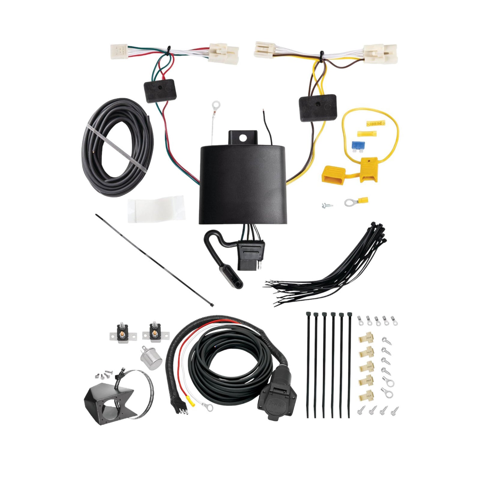

FREE ShippingFREE SHIPPING
Estimated delivery Thu, Sep 24 - Sun, Sep 27
Order before 2 PM EST Monday–Friday for same-day processing
Guaranteed safe & secure checkout

Tekonsha is a leading manufacturer of electronic trailer brake controllers, pioneering the category in the 1970s. The lineup spans proportional units such as the Prodigy P3 and Prodigy iD, time-delayed controllers, the wireless Prodigy RF, plus vehicle-specific wiring harnesses, adapters and trailer brake components engineered for smooth, predictable stopping at any speed.
Tekonsha Engineering Company began in 1964 building RV steps and mirrors. Within a few years it had found its real calling, and by the 1970s Tekonsha was pioneering the manufacture of electronic trailer brake controllers, the product category that still defines the brand. More than half a century later it remains the reference name in trailer braking and is part of the Horizon Global group alongside Reese, Draw-Tite, Fulton, Bulldog and Wesbar.
A brake controller is the component that tells a trailer's electric brakes how hard to work and when, and getting that right is the difference between a controlled stop and a shove from behind. Tekonsha builds both major types. Proportional controllers use an internal accelerometer to sense how quickly the tow vehicle is slowing and apply trailer braking to match, so light braking stays light and hard braking is immediate. Time-delayed controllers ramp to a preset output over a fixed interval, a simpler and more economical approach that suits occasional towing.
The current brake controller range covers most of that ground. The Prodigy iD pairs with a phone through Tekonsha's EDGE technology for setup and monitoring, the P3 offers storable settings for multiple trailers and a trilingual colour LED display, the Prodigy P2 adds a dimmable display and boost mode for heavier loads, and the Voyager keeps operation simple and dependable. The Prodigy RF mounts to the trailer itself and controls wirelessly, which suits rental fleets and drivers who swap tow vehicles.
Installation is supported by vehicle-specific brake control harnesses that plug into a factory connector rather than requiring cut-and-splice wiring, along with mounting brackets and adapters. Matched controller bundles pair a unit with the correct harness. Products are tested to meet and often exceed published industry standards.
Experts available to answer your questions
Call 888-634-94941 Year
1 compatible vehicles
| Year | Make & Model | Notes |
|---|---|---|
| 2022 - 2023 | Hyundai Kona | — |
Yes, the 2022-2023 Hyundai Kona Tekonsha Custom 7-Way + Brake Controller Install Kit (Part #TBCW70436) is designed to fit the 2022-2023 Hyundai Kona.
The 2022-2023 Hyundai Kona Tekonsha Custom 7-Way + Brake Controller Install Kit (Part #TBCW70436) fits the following vehicles: 2022-2023 Hyundai Kona. Always verify your specific year, make, and model before ordering.
The 2022-2023 Hyundai Kona Tekonsha Custom 7-Way + Brake Controller Install Kit (Part #TBCW70436) fits 2022-2023 Hyundai Kona models. The 2023 model year is the last year covered by this part number. For newer models, check for an updated version.
The 2022-2023 Hyundai Kona Tekonsha Custom 7-Way + Brake Controller Install Kit (Part #TBCW70436) Refer to the included instructions for installation details. Basic hand tools are typically all you need.
The BRAKE mate is a trailer brake control system that allows you to control trailer brakes from your vehicle. It connects to your vehicle's electrical system and includes a brake control unit that mounts under the dash, circuit breakers for power management, and a prewired connector that attaches to your trailer.
The manual does not specify which vehicle makes, models, or years are compatible with the BRAKE mate. Contact Cequent Towing Products technical service at (888) 521-0510 or consult a fitment database to confirm compatibility with your specific vehicle.
Yes. Step 4 of the installation instructions requires connecting the 4-pole flat connector to the vehicle's connector, which means your vehicle must already have a 4-pole flat connector. If your vehicle does not have one, the BRAKE mate cannot be installed using these instructions.
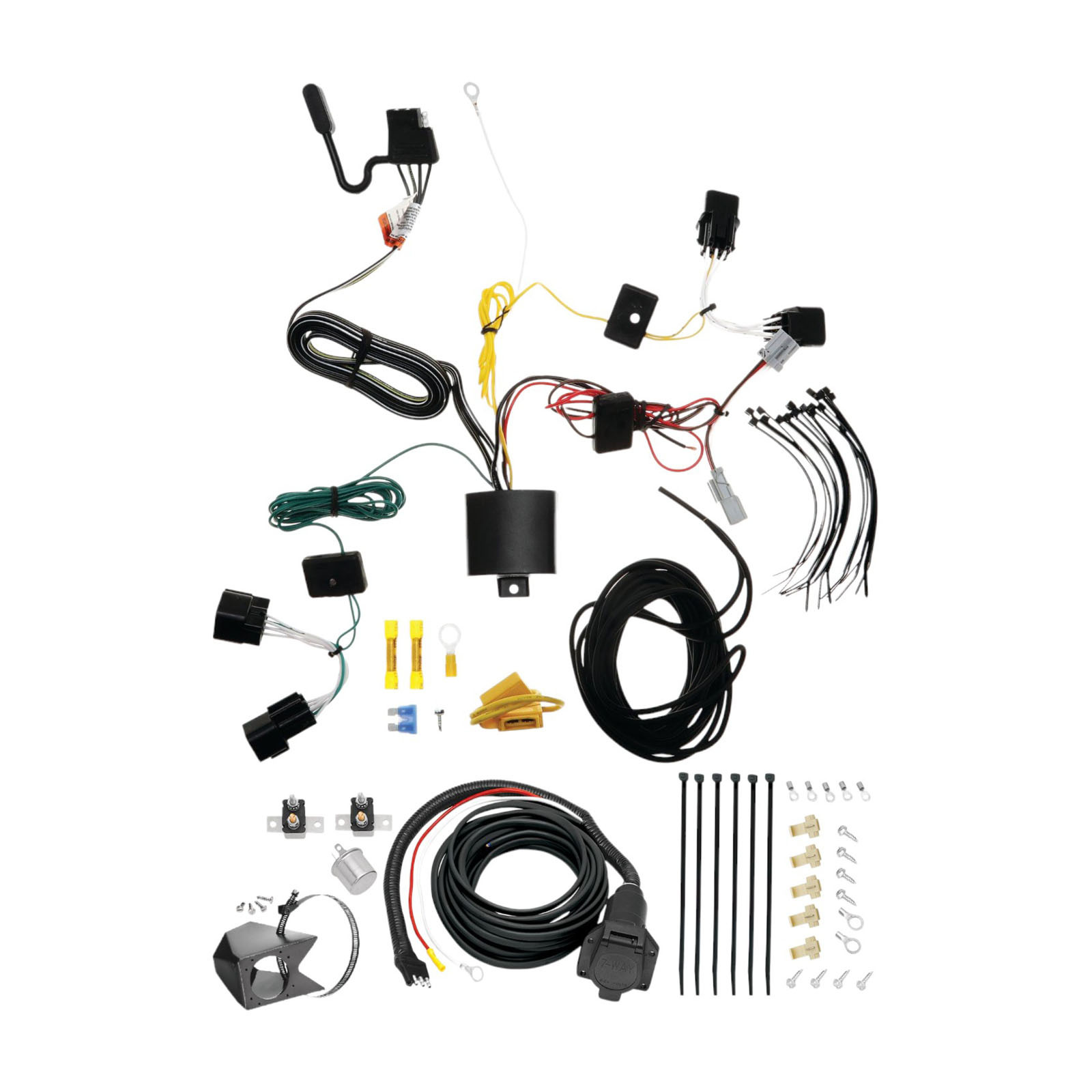
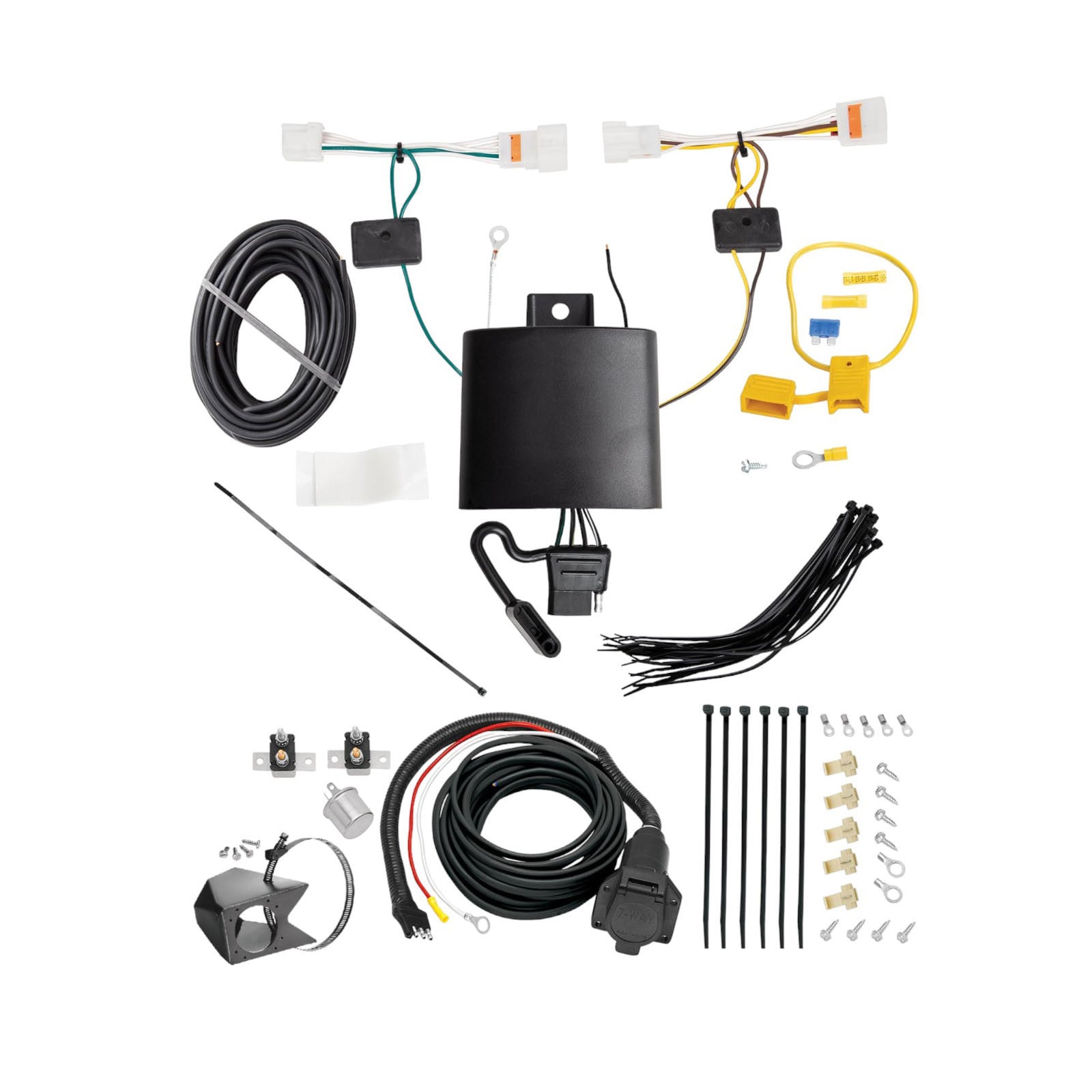
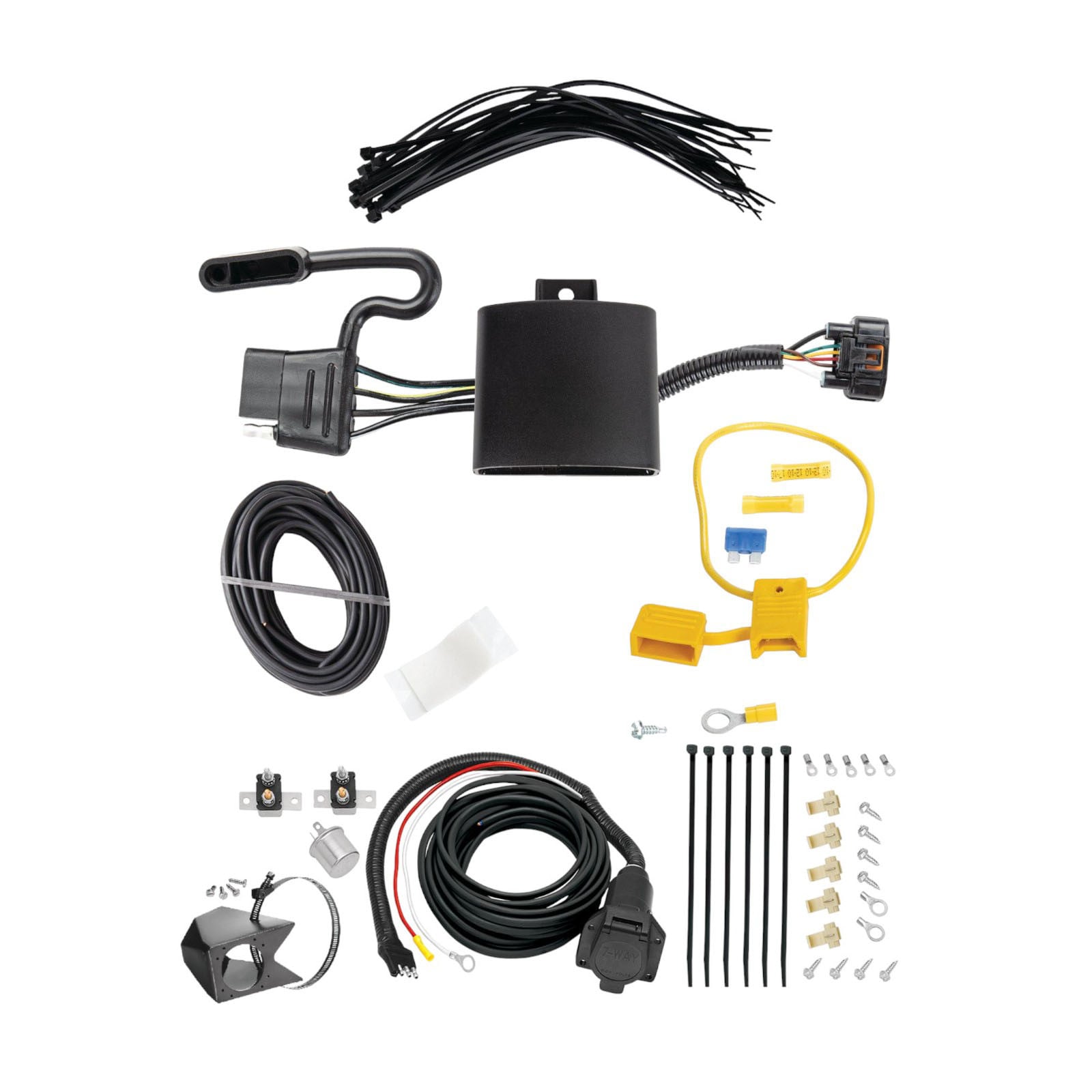
The kit includes: 1 prewired connector, 1 heavy duty flasher, 1 20 amp circuit breaker, 1 40 amp circuit breaker, 5 #10 G-ring connectors, 2 3/8" G-ring connectors, 5 Scotch locks, 8 self-tapping screws, and 6 wire tie straps.
The manual does not specify required tools. However, based on the installation steps, you will likely need a drill (to create a firewall hole if one does not exist), wire strippers, a screwdriver (for self-tapping screws), and possibly a crimper or pliers for ring connectors. Contact technical service at (888) 521-0510 for a complete tool list.
The manual does not specify whether the battery must be disconnected before installation. Contact Cequent Towing Products technical service at (888) 521-0510 for safety guidance before beginning work.
Mount the bracket for the round connector on the bumper if that is where you intend to install it. Some hitches have built-in brackets, so check your hitch first before mounting a separate bracket.
Mount the brake control unit under the dash onto something firm. The unit must be securely fastened to a solid surface.
Mount the 2 circuit breakers (20 amp and 40 amp) end to end on the firewall within reach of the BLUE/BLACK cable. Secure them with the self-tapping screws supplied in the kit.
You may need to drill a hole through the firewall to run the BLUE/BLACK 2-strand wire from the engine bay into the cab. Look for an existing spot first; if none is available, drill a hole and seal it with a rubber grommet or silicone to prevent water and debris from entering the cab.
Some hitch brackets may need to be cut to allow the various connectors to pass through. Check your specific hitch bracket during installation; if it blocks connector passage, you will need to cut it.
Yes. In step 9, you must cut the black wire to create two open ends. These ends are then fitted with ring connectors and attached to the 40 amp and 20 amp circuit breakers respectively.
WHITE = ground wire; BLUE/BLACK = 2-strand power and trailer brake wire (runs from rear connector to front of vehicle and through firewall); RED = power wire from brake control unit; BLUE = trailer brake wire from brake control unit; GREEN = wire from brake control unit to brake switch.
Connect the WHITE ground wire to the frame of the vehicle. This provides the ground connection for the system.
Run the BLUE/BLACK 2-strand wire along the frame rail to the front of the vehicle, avoiding the exhaust, axles, and brake cables. Secure it with the plastic tie straps supplied. Then run it up the firewall, avoiding the steering mechanism, and secure it with ties.
Split the BLUE/BLACK 2-strand wire down the middle. Connect the RED (power) wire of the brake control unit to the BLACK wire using a Scotch lock. Connect the BLUE (trailer brake) wire of the brake control unit to the BLUE wire using a Scotch lock. Connect the WHITE wire of the brake control unit to the ground on the vehicle body. Connect the GREEN wire of the brake control unit to the inactive side of the brake switch.
Run a heavy gauge wire from the battery or equivalent power source to the battery side of either circuit breaker. Attach a #10 G-ring connector to one end of the wire. Then split a wire off this main wire to the 20 amp breaker using a Scotch lock and attach a #10 G-ring connector to the end of this wire. Alternatively, you can run a jumper between the two breakers.
The circuit breakers protect the electrical system. The 40 amp breaker is connected to the auxiliary side of the wire going to the rear connector. The 20 amp breaker is connected to the auxiliary side of the wire going through the firewall to the brake control unit.
The heavy duty flasher is a replacement turn signal flasher. If your turn signals blink too fast after installation, replace your vehicle's original turn signal flasher with the one supplied in the kit.
After attaching the round connector with self-tapping screws, test the connector for: running lights, brake lights, turn signals, and hot wire (power). Note that the brake control output cannot be tested unless a trailer is connected to the connector.
If the turn signals are blinking too fast after installation, replace the turn signal flasher with the heavy duty flasher supplied in the BRAKE mate kit.
After drilling a hole through the firewall to run the BLUE/BLACK wire into the cab, seal the hole with a rubber grommet or silicone to prevent water and debris from entering the vehicle.
When running the BLUE/BLACK 2-strand wire along the frame rail and up the firewall, avoid the exhaust, axles, brake cables, and steering mechanism. These components can damage the wire or be damaged by it. Secure the wire with the supplied plastic tie straps.
Your vehicle must have a 4-pole flat connector. Contact Cequent Towing Products at (888) 521-0510 or check a fitment database to confirm compatibility with your specific make, model, and year.
The kit includes a prewired connector, brake control unit, 20 amp and 40 amp circuit breakers, 5 #10 G-ring connectors, 2 3/8" G-ring connectors, 5 Scotch locks, 8 self-tapping screws, 6 wire tie straps, and a heavy duty flasher.
You may need to drill a hole through the firewall to run the brake wire into the cab if an existing hole is not available. The hole must be sealed with a rubber grommet or silicone.
Connect WHITE (ground) to frame, RED (power) to BLACK wire, BLUE (trailer brake) to BLUE wire, GREEN to brake switch, and run BLUE/BLACK from rear connector through firewall to brake control unit.
Test for running lights, brake lights, turn signals, and hot wire (power). Brake control output cannot be tested without a trailer connected. If turn signals blink too fast, replace the flasher with the one supplied.
Avoid routing the BLUE/BLACK wire near the exhaust, axles, brake cables, or steering mechanism. Secure all wires with the supplied plastic tie straps.
Part number 118855 is designed for Hyundai Kona. However, the manual states that specific model years and trim levels must be verified on the Horizon Global website at www.horizonglobal.com for the most up-to-date compatibility information.
Required tools: safety glasses, Phillips screwdriver, wire stripper, wire crimper, 10 mm socket, ratchet, drill with 3/32" drill bit, fish wire, and a heat gun (for heat-shrink butt connectors). A test light is also provided for verification. You will also need silicone rubber sealant (not included) to seal the grommet.
Yes. You must locate the vehicle's battery, disconnect and isolate the negative battery cable before beginning installation. The negative cable is disconnected again in step 11 before connecting the power wire to the positive battery terminal.
Yes. You must drill a 3/32" hole to secure the white ground wire using the eyelet and screw provided. The manual states: do not drill into the vehicle floor or bed, and verify what is behind any surface prior to drilling to avoid damage to the vehicle and personal injury.
The fuse rating is 15 amps. A 15-amp fuse is provided in the hardware kit and must be installed in the fuse holder after the negative battery cable is reconnected.
After installation, test and verify the connector with a test light or trailer. For the initial test, reset the vehicle electrical system by temporarily removing the key from the ignition. All connections must be complete for the T-One® Connector to function properly. Do not exceed the towing manufacturing rating or specific amperage ratings stated on the product.
Clean the 4-way flat connector after each use. Before each trip, inspect the 4-way flat harness to ensure no damage to terminals and connection points. Ensure the harness does not get pinched in door latches, trailer connection points, or contact the road surface. Clean the connection and add dielectric grease (sold separately) to the terminal pins.
The T-One® Connector (part number 118855) is a trailer lighting module designed for Hyundai Kona vehicles. It provides a 4-way flat connector for trailer lighting and is installed by connecting to the vehicle's taillight wiring harness and battery. The module includes a black box that mounts behind the rear bumper fascia.
Yes, but with a critical restriction: if your vehicle is equipped with the Start/Stop option, you must connect the module only to the main vehicle battery. Do not connect the module power wire to the support battery. Failure to connect to the vehicle main battery may result in damage.
The installation difficulty is rated as Expert. Installation times are listed on Horizon Global websites or in downloadable application guides. The difficulty level is based on time and effort involved and may vary depending on installer expertise, vehicle condition, and availability of proper tools and equipment.
Mount the black box behind the rear bumper fascia on the driver's side, from inside the cargo area. Use the double-sided tape provided. Before mounting, clean the flat mount surface area using a 50-50 mixture of rubbing alcohol and water. The mounting point should be behind the partially removed trim panel close to the grommet.
The connector has four ends with different colored wires: brown and red wires connect to the driver's side taillight, yellow wire connects to the driver's side taillight in the bumper, and green wire connects to the passenger's side taillight in the bumper. Insert each T-One® Connector end between the vehicle and taillight connectors. Ensure all connector surfaces are clean and free of dirt before insertion.
Locate the grommet underneath the exposed area on the driver's side. Carefully slit the grommet so that both the yellow and green wires and the T-One® Connector ends pass through it to the other side of the vehicle's body. When routing wires through a grommet and along the exterior, avoid hot pipes, heat shields, the fuel tank, and other points that may pinch or break the wire. After installation, seal the slit grommet with silicone rubber (not included) to prevent moisture or dirt from entering the vehicle.
After disconnecting the negative battery cable, cut the fuse holder wire and attach the ring terminal to the vehicle's positive (+) battery cable. Connect the other end of the fuse holder to the black 12 gauge wire using the yellow heat-shrinkable butt connector provided. Route the black 12 gauge wire from the front of the vehicle rearward along the frame rail, avoiding hot pipes, heat shields, fuel tank, and pinch points. Connect the other end to the black power wire on the T-One® Connector's black box using another yellow heat-shrinkable butt connector. Heat each connector from the center outward until the tubing shrinks and sealant flows, then allow to cool.
1. Disconnect the negative battery cable. 2. Connect the T-One® Connector ends to the taillight connectors (brown/red to driver's side, yellow and green through grommet to bumper taillights). 3. Mount the black box behind the rear bumper fascia. 4. Ground the white wire to a suitable grounding point. 5. Connect the power wire to the positive battery terminal via the fuse holder and black 12 gauge wire. 6. Reconnect the negative battery cable. 7. Install the 15-amp fuse. 8. Test with a test light or trailer. 9. Reset the electrical system by temporarily removing the ignition key.
Locate a suitable grounding point near the black box, such as an existing ground stud. If no existing stud is available, drill a 3/32" hole. Do not drill into the vehicle floor or bed. Clean dirt and rustproofing from the area before drilling. Verify what is behind any surface prior to drilling to avoid damage to the vehicle and personal injury. Do not drill into any exposed surfaces. Secure the white wire using the eyelet and screw provided.
The T-One® Connector uses the following wire colors: brown and red wires connect to the driver's side taillight connector; yellow wire connects to the driver's side taillight in the bumper; green wire connects to the passenger's side taillight in the bumper; white wire is the ground wire that connects to a ground stud or drilled hole; black 12 gauge wire connects to the vehicle's positive battery terminal via the fuse holder; black power wire on the module connects to the black 12 gauge wire.
Two yellow heat-shrinkable butt connectors are provided. Use one to connect the fuse holder wire to the black 12 gauge wire, and use the other to connect the black 12 gauge wire to the black power wire on the T-One® Connector's black box. To apply: heat the connector using a heat gun, starting in the center of the splice connector and heating from the center out to the edges on each end until the tubing shrinks and sealant flows. Allow to cool before inspecting the splice.
Always wear safety glasses during installation. Do not touch the negative battery terminal to the positive battery terminal, as serious injury and damage to the vehicle's electrical system can occur. Read and follow all warnings and cautions printed on the vehicle's battery. Do not exceed the towing manufacturing rating (including in your vehicle owner's manual) or specific amperage ratings stated on the product. Overloading circuits can cause fires. Verify what is behind any surface prior to drilling to avoid damage to the vehicle and personal injury. Do not drill into vehicle floor, bed, or exposed surfaces.
First, ensure all T-One® Connector ends are fully inserted and locked in place. Check that the fuse is fully inserted into the fuse holder with no breaks. Verify the fuse holder is connected properly to the positive post of the battery. Ensure the module is connected to B+ (positive). Using a tester or voltmeter, check for voltage on either side of the yellow butt connector near the module. Remove the module's power fuse for 10 seconds and repeat the test. If the issue persists, check chassis grounds and ensure ring terminals are in full contact with the vehicle chassis.
No power to the 4-way connector can indicate several issues: the fuse may not be fully inserted or may be broken; the fuse holder may not be connected properly to the positive battery post; the module may not be connected to B+; or the installation may have activated circuit protection. To troubleshoot: ensure the fuse is fully inserted with no breaks; verify the fuse holder connection to the positive battery post; check for voltage using a tester or voltmeter on either side of the yellow butt connector near the module; start the vehicle and turn off all functions (tail lights, brake, turns); remove the module power fuse for 10 seconds and repeat the test.
After installation is complete, test and verify the connector with a test light or trailer. For the initial test, reset the vehicle electrical system by temporarily removing the key from the ignition. All connections must be complete for the T-One® Connector to function properly. A test light is provided in the hardware kit for this purpose.
Open the rear hatch. On the driver's side, use a trim panel tool, Phillips screwdriver, or 10 mm socket to remove the plastic threshold cover, cargo trays, and the side panel. Be careful not to break the mounting tabs. This exposes the vehicle's taillight wiring harness.
Underneath the vehicle on the passenger's side, locate the black environmental cover. Using a trim panel tool, remove the 3 plastic clips carefully to avoid damaging them. Using a 10 mm socket, remove the plastic nut and set the cover aside.
Route the 4-way flat connector through the driver's side panel and threshold into the storage compartment and store it there when not in use.
After reconnecting the negative battery cable, install the 15-amp fuse into the fuse holder. Then test and verify the installation with a test light or trailer. For the initial test, reset the vehicle electrical system by temporarily removing the key from the ignition. Ensure all connections are complete for the T-One® Connector to function properly.
After completing the electrical connections, reinstall any trim panels, cargo trays, threshold covers, and other items that were removed during installation. Be careful not to pinch or cut the wires when reinstalling these components.
Clean the 4-way flat connector after each use. Before each trip, perform a pre-trip inspection of the 4-way flat harness to ensure no damage to terminals and connection points for proper lighting connection and operation. Ensure the harness does not get pinched in door latches, trailer connection points, or contact the road surface. Clean the connection and add dielectric grease (sold separately) to the terminal pins.
The hardware kit includes: Perma Seal heat-shrinkable butt connectors (yellow), ring terminals, #8 screws, a 15-amp fuse, double-sided tape, a fuse holder, a 3/32" drill bit, a 10 mm socket, fish wire, and 6" wire ties. A test light is also provided. Silicone rubber sealant is not included but is required for sealing the grommet.
The black power wire is 12 gauge (12 ga.). This wire connects from the fuse holder to the black power wire on the T-One® Connector's black box using a yellow heat-shrinkable butt connector.
If the installation activates circuit protection, start the vehicle and turn off all functions: tail lights (head lights), brake, and turns. Remove the module power fuse for 10 seconds and repeat the test. This should reset the circuit protection.
First, ensure all T-One® Connector ends are fully inserted and locked in place. Remove the module's power fuse for 10 seconds and repeat the test. If still not functioning, check that the fuse is fully inserted into the fuse holder with no breaks, and verify the fuse holder is connected properly to the positive post of the battery. Check chassis grounds and ensure ring terminals are in full contact with the vehicle chassis.
Possible causes include: the fuse is not fully inserted or is broken; the fuse holder is not connected properly to the positive battery post; the module is not connected to B+ (positive); or the installation has activated circuit protection. To diagnose, verify the fuse is fully inserted with no breaks, check the fuse holder connection, use a tester or voltmeter to check for voltage on either side of the yellow butt connector near the module, and remove the module power fuse for 10 seconds and repeat the test.
Start the vehicle and turn off all functions: tail lights (head lights), brake, and turns. Remove the module power fuse for 10 seconds and repeat the test. This should reset the circuit protection.

Total for 1 item:
$18.99
No reviews have been added for this product.