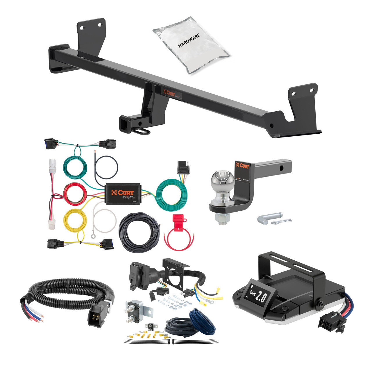
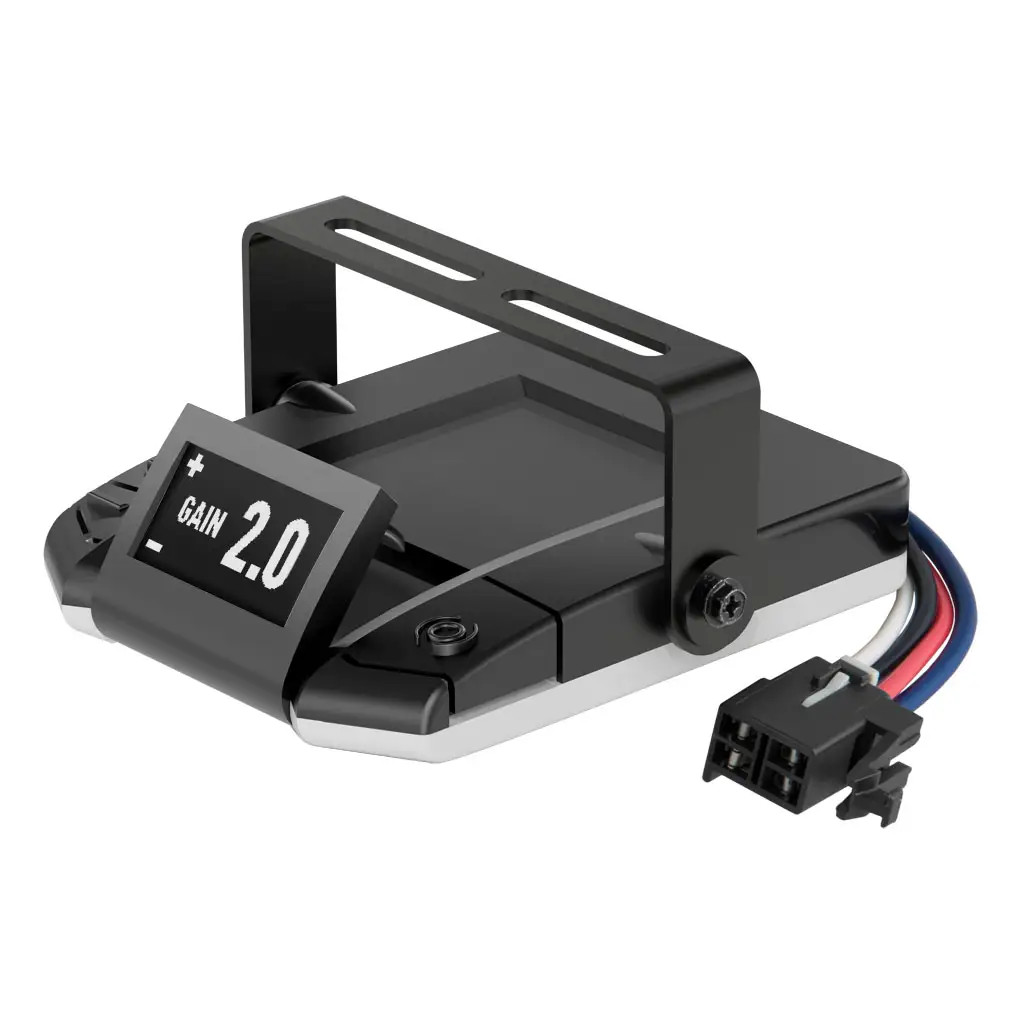
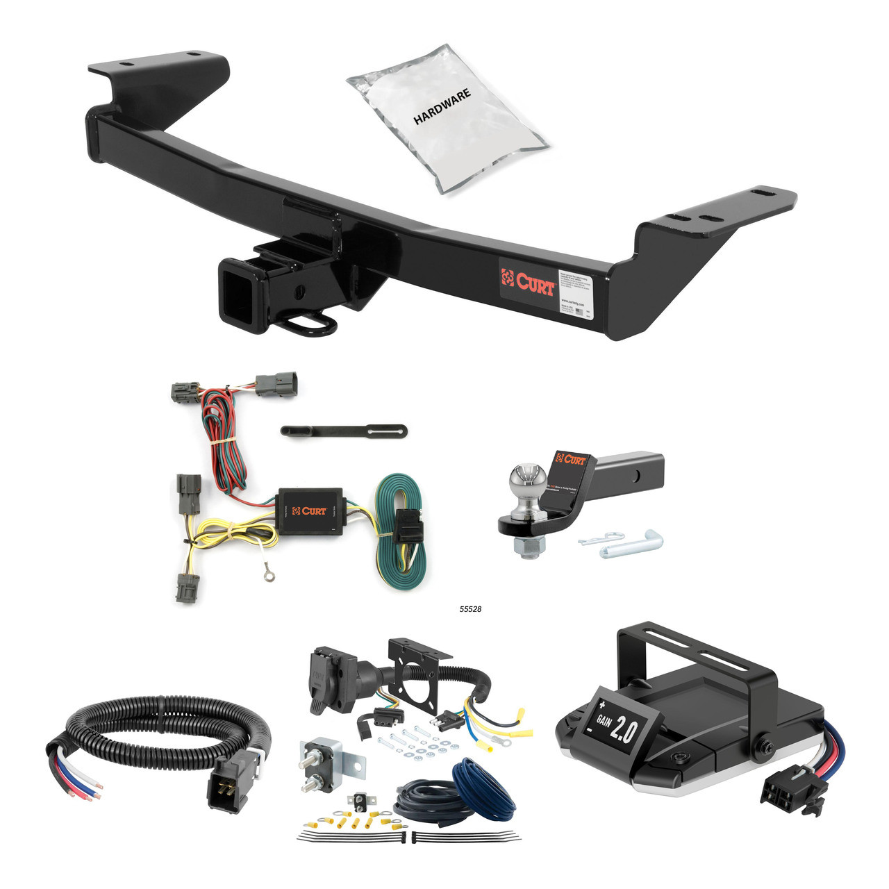
22-23 Hyundai Kona Excluding electric 1.25 CURT Trailer Hitch + Assure Proportional Brake Controller Kit HBCW1427CURTOriginal price was $1,019.60. Current price is $760.78.In Stock
View productOur in-house experts typically reply within one business day.

CURT
Verify Fitment
Select your vehicle to confirm this part fits.
2022 - 2023 Hyundai Kona N
Confirmed to Fit




Always the correct part
We know our products
Quality Products
Free Shipping!
Always the correct part
We know our products
Quality Products
Free Shipping!
| Finish | GLOSS BLACK POWDER COAT |
| Main Body Shape | Round |
| Material | Carbon Steel |
| Mount Type Description | Not Applicable |
| Receiver Tube Size | 2 IN |
| Side Application Type Description | Not Applicable |
| Tongue Weight (TW) | 750 LB |
| Warranty | Limited Lifetime Warranty (One-Year Finish, One-Year Parts) |
| Weight Carrying Capacity (WC) | 5,000 LB |
| Weight Distribution (WD) | 6,000 LB |
| Weight Distribution Tongue Weight (WDTW) | 750 LB |
| Battery-Powered | Yes |
| Converter Type | Universal, Potted, Powered, Protected, PWM |
| Electrical Component Location | Vehicle / Trailer |
| Electrical System Type | 3W |
| Material | THERMOPLASTIC RUBBER |
| Mount Type Description | Not Applicable |
| Output Type | 4-Way Flat |
| Side Application Type Description | Not Applicable |
| T-Connector Location | S1,S2 |
| Tail Light Circuits | 6.0 Amps |
| 29 | Pin |
| Turn and Brake Circuits | 3.0 Amps |
| Warranty | One-Year Limited Warranty |
| Side Application Type Description | Blank |
| Tongue Weight (TW) | 350 LB |
| Warranty | Limited Lifetime Warranty (One-Year Finish, One-Year Parts) |
| Drop | 3-1/4 IN |
| Finish | GLOSS BLACK POWDER COAT |
| Gross Trailer Weight (GTW) | 3,500 LB |
| Material | Blank |
| Mount Type Description | Blank |
Notes:
Notes:

CURT offers a variety of high-quality trailer hitches and accessories for select vehicle models. Find the perfect fit for your towing needs at TowUniverse.
CURT, a Lippert brand, offers a complete line of towing products and is the leading manufacturer of custom-fit trailer hitches. We offer the broadest selection of custom-fit hitches, and each one is designed, welded, and coated in Wisconsin.
CURT is also a leader in flat towing products, as well as 5th wheel, gooseneck, and weight distribution hitches, ball mounts, electrical components, cargo solutions, and other towing accessories.
For everything from passenger cars and vans to full-size pickups and SUVs, CURT is 'The First Name in Towing Products®.'

Experts available to answer your questions
Call 888-634-9494One-Year Limited
1 compatible vehicles
| Year | Make & Model | Notes |
|---|---|---|
| 2022 - 2023 | Hyundai Kona N | — |
Yes, the 22-23 Hyundai Kona N 1.25 CURT Trailer Hitch + Assure Proportional Brake Controller Kit HBCW1430 (Part #HBCW1430) is designed to fit the 2022-2023 Hyundai Kona N.
The 22-23 Hyundai Kona N 1.25 CURT Trailer Hitch + Assure Proportional Brake Controller Kit HBCW1430 (Part #HBCW1430) fits the following vehicles: 2022-2023 Hyundai Kona N. Always verify your specific year, make, and model before ordering.
The 22-23 Hyundai Kona N 1.25 CURT Trailer Hitch + Assure Proportional Brake Controller Kit HBCW1430 (Part #HBCW1430) fits 2022-2023 Hyundai Kona N models. The 2023 model year is the last year covered by this part number. For newer models, check for an updated version.
The 22-23 Hyundai Kona N 1.25 CURT Trailer Hitch + Assure Proportional Brake Controller Kit HBCW1430 (Part #HBCW1430) Refer to the included instructions for installation details. Basic hand tools are typically all you need.
Yes, CURT part 13427 is designed for 2020-present Hyundai Palisade SUVs. Verify your vehicle matches this model and year range before purchasing.
The CURT 13427 has two capacity ratings depending on how it is used. As a weight-carrying hitch: 5,000 lbs trailer weight and 750 lbs tongue weight. As a weight-distribution hitch: 6,000 lbs trailer weight and 750 lbs tongue weight. Never exceed your vehicle manufacturer's recommended towing capacity.
The hitch weight is 45 lbs.
Required tools are: ratchet, torque wrench, 6-inch socket extension, 11mm socket, 14mm socket, 17mm socket, 19mm socket, straight screwdriver, and 19mm boxed-end wrench. Safety glasses must be worn at all times during installation.
No, drilling is not required. The hitch uses existing vehicle weldnuts and tube spacers in the frame.
Two people may be required to ease installation, though the manual does not state whether a second person is mandatory or optional.
Three components must be temporarily removed or lowered: (1) the spare tire, lowered using an 11mm socket and ratchet; (2) the driver-side underbody panel, removed by taking out 3 push clips and turning 2 plastic retainers counterclockwise with a 14mm socket; and (3) the exhaust, lowered by unhoking the 4 rearward-most exhaust isolators. The exhaust must be supported while lowered.
The hitch includes: (1) four M10×1.25 hex cap screws (part 10-10271); (2) four M12×1.75 hex cap screws (part 10-10283); (3) four M12×1.75 hex nuts (part 20-00136); (4) eight 1/2-inch S-CON washers (part 30-00149); and (5) four 7/16-inch S-CON washers (part 30-00163). The M10 fasteners and 7/16-inch washers install into existing vehicle weldnuts on the driver and passenger frame rails. The M12 fasteners, hex nuts, and 1/2-inch washers also attach to the frame rails using existing tube spacers.
Torque all M12 fasteners (12mm) to 79 lb-ft and all M10 fasteners (10mm) to 48 lb-ft. Use a torque wrench to achieve these values.
No. Step 4 instructs to 'loosely install fasteners' when raising the hitch into position. Fasteners are fully torqued in step 5 after the hitch is positioned over the exhaust.
After torquing all fasteners, reinstall in this order: (1) the driver-side underbody panel; (2) raise the spare tire back into position; (3) reinstall the exhaust isolators.
Safety glasses must be worn at all times during installation. When lowering the exhaust, it must be supported—do not allow it to hang unsupported. Never exceed your vehicle manufacturer's recommended towing capacity when using the hitch.
Periodically check that all fasteners are tight and all structural components are sound. The manual does not specify a retorque interval or maintenance schedule beyond these periodic checks.
Professional installation time is approximately 90 minutes. Novice (DIY) installation time is approximately 39–45 minutes, depending on experience level.
CURT Manufacturing warrants the product to be free of defects in material and workmanship at the time of retail purchase by the original purchaser. If defective, CURT may repair or replace the product at their option when returned prepaid with proof of purchase. Warranty is voided by alteration, misuse, or improper installation. CURT's liability is limited to repair or replacement and excludes incidental or consequential loss or damage.
The product complies with safety specifications and requirements for connecting devices and towing systems of the state of New York, V.E.S.C. Regulation V-5 and SAE J684.
Yes, the CURT 13427 is designed for 2020-present Hyundai Palisade SUVs.
Weight-carrying: 5,000 lbs trailer / 750 lbs tongue. Weight-distribution: 6,000 lbs trailer / 750 lbs tongue. Never exceed your vehicle manufacturer's recommended towing capacity.
No, drilling is not required. The hitch uses existing vehicle weldnuts and frame spacers.
Ratchet, torque wrench, 6-inch socket extension, 11mm/14mm/17mm/19mm sockets, screwdriver, 19mm boxed-end wrench, and safety glasses.
M12 fasteners: 79 lb-ft. M10 fasteners: 48 lb-ft.
Spare tire, driver-side underbody panel, and exhaust isolators must be temporarily removed or lowered. All are reinstalled after hitch installation.
Wear safety glasses at all times. Support the exhaust when lowering it. Never exceed your vehicle manufacturer's recommended towing capacity.
Periodically check that all fasteners are tight and structural components are sound.
The kit includes: one 30 amp auto-resetting circuit breaker, two #10 ring terminals, two 3/8" ring terminals, two 1/2" ring terminals, three 12-10 gauge butt connectors, 10 feet of 10 ga black/white duplex wire, 20 feet of 10 ga blue cross-linked wire, and eight 8.5" cable ties.
Yes, but with a critical difference: these vehicles require the stop signal wire to be spliced to the light green wire on the turn signal harness connector under the dash, not to the brake pedal switch. Do NOT connect to the red wire with green stripe, as serious damage may occur. All other vehicles connect to the brake pedal switch instead.
You will need: a test light, wire stripper/cutter, crimp tool, and 3/8" box end wrench. The test light is used to identify the cold (switched) side of the brake pedal switch.
Yes. The manual cautions to disconnect the tow vehicle's negative battery cable before installation. Reconnect it only in the final step after all wiring is complete.
Mount the 30 amp circuit breaker near the tow vehicle's positive battery terminal. This keeps the power wire run as short as possible and protects the circuit.
Use 10 gauge (10 ga) black wire from the duplex wire included in the kit. Strip 3/8" of insulation from each end. Crimp a #10 ring terminal to the end that attaches to the circuit breaker stud labeled 'BAT', and a 3/8" or 1/2" ring terminal (sized to fit your battery terminal) to the end that attaches to the positive battery terminal.
Feed the 10 ga duplex wire from the brake controller in the cockpit through the firewall into the engine compartment toward the battery. Cut to length as needed. At the battery end, crimp a 3/8" or 1/2" ring terminal to the white wire and a #10 ring terminal to the black wire. Attach the black wire to the circuit breaker stud labeled 'AUX' and tighten the nut with a 3/8" box end wrench.
When passing the duplex wire through the firewall into the engine compartment, use an existing grommet, add a new grommet, or fill the hole with silicone rubber to insulate and protect the wire. The same protection applies when passing the blue cross-linked wire through any sheet metal at the rear of the vehicle.
In the cockpit, attach the black duplex wire to the brake controller's battery wire (typically black) and the white duplex wire to the brake controller's ground wire (typically white). Use either one of the supplied yellow butt connectors or solder the leads together and insulate with heat shrink tubing.
Locate the brake pedal switch on the back side of the vehicle's brake pedal. Use a test light or volt meter to identify the 'cold' or switched side—this terminal will only show power when the brake pedal is depressed. Attach the stop signal wire (typically red) from the brake controller to the cold side of the switch using a wire tap.
Locate the semi-circle turn signal harness connector on the steering column under the dash. It has two rows of wires: a row of four and a row of seven. Attach the stop signal wire (typically red) from the brake controller to the light green wire using a wire tap. Do NOT connect to the red wire with green stripe, as serious damage may occur.
Feed the 10 ga blue cross-linked wire from the brake controller to the trailer connector at the rear of the vehicle, taking up any slack in the wire. When passing through any sheet metal, use an existing grommet, add a new grommet, or fill the hole with silicone rubber to protect the wire.
Attach the blue cross-linked wire to the brake controller's electric brake wire (typically blue) using one of the supplied yellow butt connectors or by soldering and insulating with heat shrink tubing. At the rear of the vehicle, trim any loose blue wire and attach it to the trailer connector's electric brake terminal. Refer to the trailer connector's wiring diagram for the correct terminal location.
Secure any loose wires with the cable ties provided. Connect the black power wire from the circuit breaker to the positive side of the battery. Connect the white ground wire from the brake controller to the negative side of the battery. Finally, reconnect the tow vehicle's negative battery cable to the battery.
The circuit breaker is 30 amps and auto-resetting. It must be mounted near the positive battery terminal and connected directly to the positive battery terminal via the included black 10 gauge wire.
Use a 3/8" box end wrench to tighten the nuts on the circuit breaker studs labeled 'BAT' and 'AUX'.
The kit includes 10 feet of 10 gauge black/white duplex wire for the battery and brake controller connections, and 20 feet of 10 gauge blue cross-linked wire for the electric brake signal to the trailer connector.
Black wire connects to the positive battery and circuit breaker. White wire connects to the brake controller ground and negative battery. Red wire is the stop signal wire from the brake controller. Blue wire is the electric brake signal wire. The manual notes these are 'typically' these colours but recommends confirming with your brake controller documentation.
Yes. You can solder the leads together and insulate with heat shrink tubing as an alternative to using the supplied yellow butt connectors. This applies to connections between the duplex wire and the brake controller wires, and between the blue cross-linked wire and the brake controller.
The black power wire must connect directly to the positive battery terminal via the 30 amp circuit breaker. Connecting to the fuse panel or any other accessory wiring may damage vehicle wiring and cause trailer brake failure. The circuit breaker protects the circuit and must be the only protection between the battery and the brake control system.
Do NOT connect the stop signal wire to the red wire with green stripe on the turn signal harness. Serious damage may occur. Connect only to the light green wire. Also, do not connect to the brake pedal switch on these vehicles; use the turn signal harness instead.
The kit is universal but requires an existing trailer connector and brake controller. 1989-1991 Ford E & F-Series with ABS use a different stop signal connection (turn signal harness instead of brake pedal switch). Consult your brake controller documentation for compatibility.
No drilling is required. The kit connects to existing components: the battery, brake controller, brake pedal switch (or turn signal harness on 1989-1991 Ford E & F-Series with ABS), and trailer connector.
Do NOT connect the stop signal wire to the red wire with green stripe on the turn signal harness—serious damage may occur. Connect to the light green wire instead, and do not use the brake pedal switch.
Connecting to the fuse panel or accessory wiring may damage vehicle wiring and cause trailer brake failure. The 30 amp circuit breaker must be the only protection between the battery and the brake control system.
The 4-way flat electrical adapter converts a vehicle's 4-way flat trailer connector to other trailer connector types (6-way round, 7-way RV blade, or dual 4-way flat). This allows you to tow trailers with different connector styles. Single-output models (57184, 57183, 57185, 57626, 57676) convert to one connector type; dual-output models (57604, 57624, 57672, 57674, 57102) provide two different connector outputs simultaneously.
Yes. Your vehicle must be equipped with a 4-way flat trailer connector. If your vehicle does not have one, you will need to install a custom wiring harness or other 4-way flat trailer connector before installing this adapter.
Both convert a 4-way flat connector to a 7-way RV blade. The difference is that 57185 includes a mounting bracket, while 57184 does not.
Both convert a 4-way flat connector to a 6-way round. The difference is that 57626 includes a mounting bracket, while 57183 does not.
Curt offers three dual-output models that provide both a 4-way flat and a 7-way RV blade output: part numbers 57672, 57674, and 57102. All three include a mounting bracket.
Curt offers two dual-output models that provide both a 4-way flat and a 6-way round output: part numbers 57604 and 57624. Both include a mounting bracket.
You will need: a 1/8" drill bit, drill, Phillips screwdriver, wire stripper, cutting tool, terminal crimpers, and a test light. The manual also lists three self-tapping screws (#10 - 1/2") as required, though these are not included with the product.
No. The three self-tapping screws (#10 - 1/2") used to attach the mounting bracket are not included and must be purchased separately.
Mount the combination harness in a location on the tow vehicle that is within reach of the trailer's wiring harness and near the center of the vehicle. The mounting bracket (if included) should be attached to the vehicle's bumper or other suitable surface.
Yes. You must drill two 1/8" holes: one for the grounding point and one (or more) for the mounting bracket. Before drilling, you must check for brake lines, fuel lines, wiring and other components that may be hidden behind or under the surface to avoid damage.
No. You must never attach the mounting bracket directly to the hitch by cutting, welding or drilling into the hitch. Mount it to the vehicle's bumper or other suitable surface instead.
The adapter uses four wires: Yellow (auxiliary or back-up lights), Blue (electric brakes), Black (positive power with appropriate inline fuse), and White (ground). All wires except black and white must be connected using 12 gauge (minimum) wire and butt connectors to the appropriate vehicle functions.
The white wire is the ground connection. It must be attached with a ring terminal to a 1/8" hole drilled in a suitable grounding point on the vehicle using a #10 - 1/2" self-tapping screw. This ground connection is required for the harness to work properly. The white wire on the vehicle's 4-way flat connector does not support the ground (-) functions of the combination harness.
Yes. The black wire (positive power) must be connected with an appropriate inline fuse. The manual does not specify the fuse amperage rating.
Use 12 gauge (minimum) wire for all connections. The manual specifies this minimum gauge for the remaining wires (yellow, blue, and black) when connecting to appropriate vehicle functions.
Failing to properly ground the product can cause loss of warranty, overheating and potential fire. The white wire must be securely attached to a clean grounding point using a #10 - 1/2" self-tapping screw in a 1/8" hole. The area must be clean of dirt, debris or undercoating.
Before drilling, you must check for brake lines, fuel lines, wiring and any other components that may be hidden behind or under the surface. Drilling into these components can cause damage and personal injury.
Do not exceed the product rating or the tow vehicle lamp load rating, whichever is lower. Exceeding either rating can cause damage or unsafe operation.
Confirm proper function with a test light or by using a properly functioning trailer. This verifies that all connections are working correctly before towing.
Secure any loose wires using cable ties or equivalent product to prevent them from moving, catching on components, or becoming damaged.
Your vehicle must have a 4-way flat trailer connector. If it does not, you will need to install a custom wiring harness or other 4-way flat connector first. Check the part number table to confirm the adapter converts to the connector type you need.
You must purchase three #10 - 1/2" self-tapping screws for the mounting bracket. You will also need an appropriate inline fuse for the black (positive power) wire; the manual does not specify the amperage.
Yes, you must drill two 1/8" holes: one for grounding and one for the mounting bracket. Before drilling, check for brake lines, fuel lines and wiring behind the surface. Never drill into the hitch.
Yellow = auxiliary/back-up lights; Blue = electric brakes; Black = positive power (needs inline fuse); White = ground (must be properly grounded or warranty is void and fire risk exists). Use 12 gauge minimum wire and butt connectors.
Proper grounding of the white wire is critical. Failing to ground it properly can cause loss of warranty, overheating and fire. The grounding point must be clean of dirt, debris and undercoating.
Test with a test light or by using a properly functioning trailer to confirm all connections work. Secure loose wires with cable ties.
Part 56491 is a wiring location guide and powered converter module system for SUVs and vans. It provides instructions for routing trailer wiring through the vehicle and includes a converter module that manages signal and power circuits for trailer lights. The system is designed to work with 12-volt negative ground electrical systems.
Part 56491 is designed for SUVs and vans with 12-volt negative ground electrical systems. The manual does not specify which vehicle makes, models or years are compatible. Contact Curt Manufacturing or consult a fitment database to confirm compatibility with your specific vehicle.
No. The converter system is designed only for 12-volt negative ground systems. Do not use it on positive ground vehicles.
You will need: ratchet, 10mm socket, 14mm socket, socket extension, cutting tool, wire stripper, wire crimper, flathead screwdriver, panel trim removal tool, and electrical tape. A fish wire (or substitute such as a cut-up wire hanger, stiff wire, rope or string) is also required to route the harness through blind holes.
The kit includes a custom wiring harness with yellow and green wire housings, a white ground wire with ring terminal, a converter module, two-sided tape, zip ties, a ground screw, a fuse holder with 10-amp fuse, and cable ties for securing the power wire to the vehicle chassis.
Yes. You must disconnect the negative battery terminal in the engine compartment on the driver side before beginning installation. Fasten this wire down and away from the battery while completing the installation process.
Yes. You must remove both the driver side and passenger side taillights. Use a panel trim removal tool to remove the taillight fastener covers, then use a 10mm socket to remove the bolts securing each taillight. Pull the taillight straight back and separate the connectors carefully without damaging the locking tabs.
Fish wire is a tool used to push or pull an electrical wire through a blind hole. It can be a cut-up wire hanger, stiff wire, rope or string. Make sure it is long enough to stick out on the other side of the hole. Insert the fish wire through the blind hole, locate it on the other side, use tape to secure the harness to the fish wire, and pull back up. If the fish wire or harness gets hung up, you may need to push back down, wiggle it around or twist the wire to loosen it.
Starting on the driver side, locate the housing with the yellow wire on the custom wiring harness. From under the vehicle bumper, attach this to the fish wire and pull the harness up to the taillight cavity. Attach the custom wiring harness to the vehicle factory wiring and attach to the taillight. Set the taillight inside the taillight cavity but do not reinstall with hardware yet. Route the housing with the green wire above the bumper and along the bumper to the passenger side of the vehicle, using zip ties as needed. Repeat the process on the passenger side using the housing with the green wire.
Locate a mounting spot for the module and secure it to the vehicle using the supplied two-sided tape and/or zip ties. The manual does not specify a particular location, so choose a spot that is accessible and protected from moisture and damage.
You should first locate an existing grounding point such as an existing screw or bolt in the frame of the vehicle. If no suitable existing fastener is available, you may drill a 3/32-inch pilot hole. Before drilling, the area must be free from rust, dirt and paint—use an abrasive pad or paper to clean it. Always check for miscellaneous items that may be hidden behind or under any surface before drilling to avoid damage and personal injury.
Drill a 3/32-inch pilot hole if an existing grounding point is not available. Before drilling, ensure the area is free from rust, dirt and paint by using an abrasive pad or paper. Always check for hidden items behind or under any surface before drilling.
The wiring harness uses the following color scheme: Yellow = Left turn, Green = Right turn, Red = Brake, Brown = Taillight, and White = Ground. The converter module also includes a black wire that connects to the positive battery terminal and a white ground wire with a ring terminal.
Route a 12-gauge wire or larger from the converter to the vehicle battery location, taking care to avoid pinch points and hot or rotating components. When passing the power wire through sheet metal, use an existing grommet, add a grommet or use silicone to protect the wire from sharp edges. Connect the black wire to the positive battery terminal using a ring terminal. Secure the power wire to the vehicle chassis using the supplied cable ties. Do not install the fuse until all other steps are complete.
The battery connection must be fuse-protected with a 10-amp maximum fuse. Do not exceed this rating. Exceeding the product rating can cause loss of warranty, overheating and potential fire.
Signal circuits are rated at 3.0 amps per side. Tail and running circuits are rated at 6.0 amps total. Do not exceed the product rating or the tow vehicle lamp load rating, whichever is lower.
Disconnect the negative battery terminal before beginning installation. Do not lay tools across the positive battery terminal (typically noted with red covers or a red '+' symbol), as this can cause a ground short resulting in sparks and/or electrical shocks. When routing the power wire, avoid pinch points and hot or rotating components. When passing the power wire through sheet metal, use an existing grommet, add a grommet or use silicone to protect it from sharp edges. Always check for miscellaneous items that may be hidden behind or under any surface before drilling to avoid damage and personal injury. Do not exceed the product rating or tow vehicle lamp load rating.
Once the custom harness is installed, verify that it is functioning by attaching the 4-flat connector to any trailer with functioning lights. The taillights on the vehicle to be towed should function along with the taillights on the vehicle that is powering them. You can also use a test light to check for proper function.
Periodic inspection of all wires and connections should be performed to ensure there is no visible damage or loose connections.
Part 56491 is designed for SUVs and vans with 12-volt negative ground electrical systems. Confirm compatibility with your specific vehicle make, model and year by contacting Curt Manufacturing or checking a fitment database.
Yes. Disconnect the negative battery terminal in the engine compartment before beginning installation.
Drilling is required only if no existing grounding point is available on the vehicle frame. If drilling is necessary, drill a 3/32-inch pilot hole in a clean, rust-free area.
Use 12-gauge wire or larger to route power from the converter to the vehicle battery.
Signal circuits are rated at 3.0 amps per side; tail and running circuits are rated at 6.0 amps total. Do not exceed the product rating or the tow vehicle lamp load rating, whichever is lower.
On Sale Today
Original price was $1,009.60. Current price is $748.78.You save $260.82 (26%)
Free Shipping
Ships free on all orders
 Authorized Dealer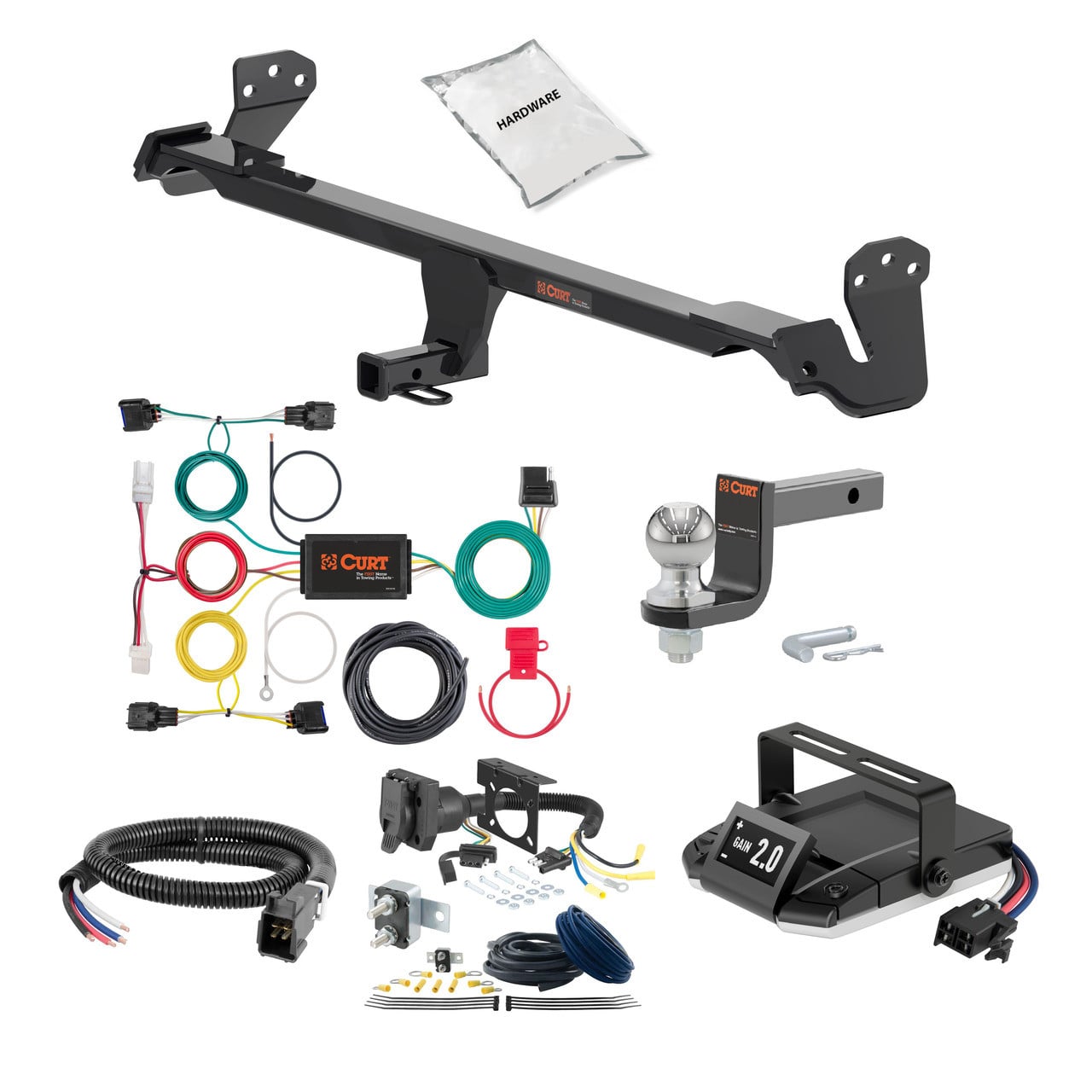


Quick Ship
In stock and ready to ship — order now!
FREE ShippingFREE SHIPPING
Estimated delivery Sun, Sep 27 - Wed, Sep 30
Order before 2 PM EST Monday–Friday for same-day processing
Guaranteed safe & secure checkout
No reviews have been added for this product.