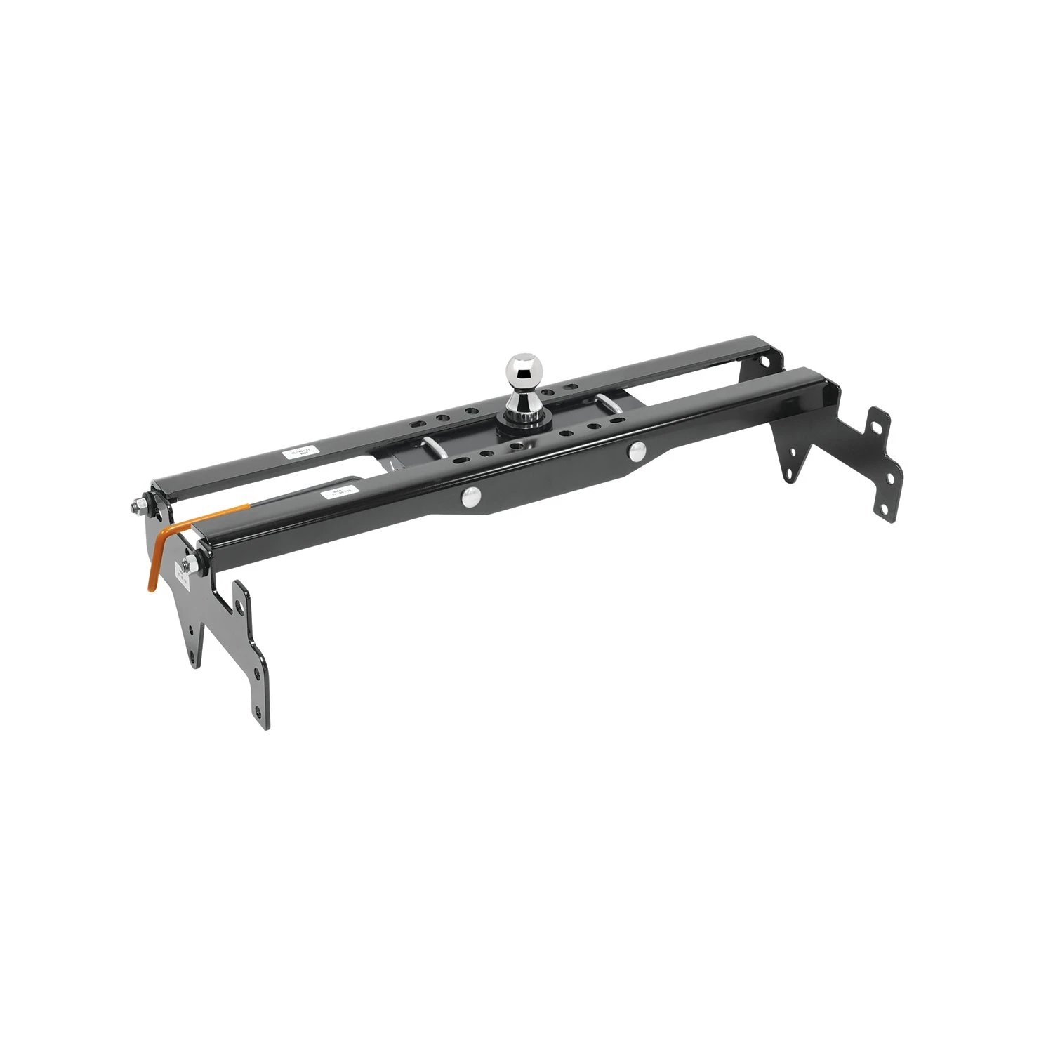
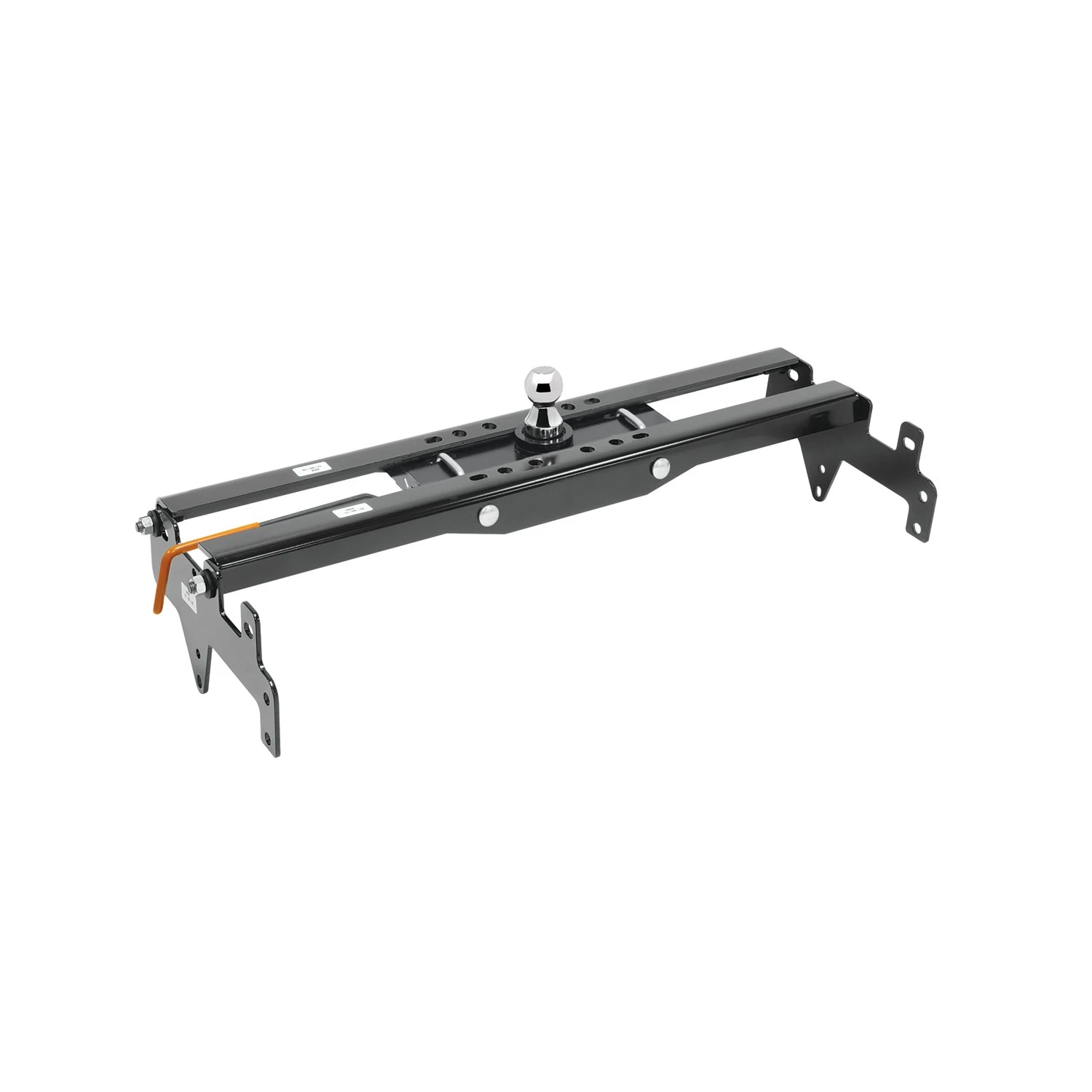
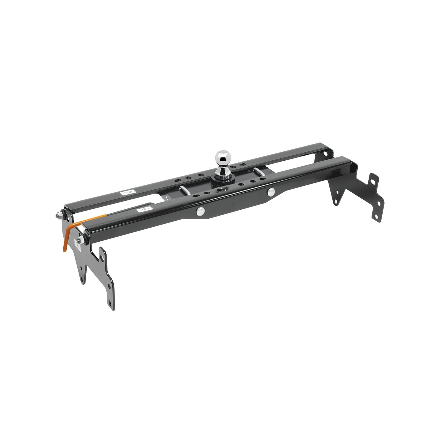
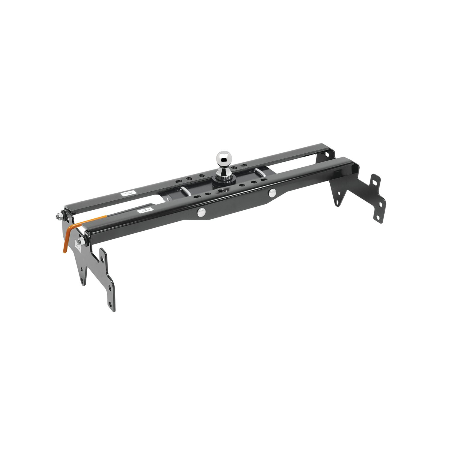
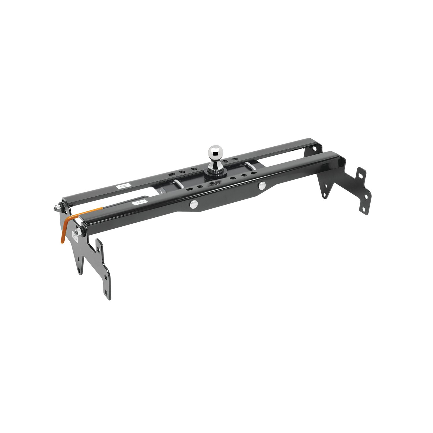
30K 2007-2013 GMC Sierra 1500 Draw-tite Hide-A-Goose Underbed Gooseneck Hitch KitDraw-titeOriginal price was $675.00. Current price is $546.18.Out of Stock
View productOur in-house experts typically reply within one business day.

Draw-tite

Always the correct part
We know our products
Quality Products
Free Shipping!
Always the correct part
We know our products
Quality Products
Free Shipping!

Draw-Tite has designed custom-fit trailer hitches since 1946 and is one of North America's most widely fitted hitch brands. Receiver hitches use solid all-welded construction and low-profile designs that follow modern vehicle contours, install with minimal bumper cutting or drilling, meet or exceed V5 CSA and SAE J684 standards, and carry a limited lifetime warranty.
Draw-Tite has been leading custom-fit trailer hitch design and engineering since its founding in 1946, and it remains one of the most widely fitted hitch brands in North America. The company's stated approach is straightforward: every hitch is tested rigorously so that it performs well beyond published industry standards, a philosophy it markets as Tested Tough. It sits within the Horizon Global towing group alongside Reese, Fulton, Bulldog, Tekonsha, Bargman and Wesbar.
Custom fit is the defining characteristic. Rather than adapting a universal design, Draw-Tite engineers a trailer hitch for a specific make, model and model year, so it bolts to existing frame locations with minimal bumper cutting or drilling. Low-profile designs follow the rear contours and aerodynamic styling of modern vehicles, which matters more than it once did now that rear fascias are shaped and sensor-equipped. Construction is solid all-welded steel for maximum strength, and every hitch meets or exceeds V5 CSA and SAE J684 standards and is backed by a nationwide limited lifetime warranty.
The range spans receiver sizes and classes to suit different loads, from 1-1/4 inch receivers for bike racks, cargo carriers and light trailers up through 2 inch receivers for heavier towing. Front mount hitches add a receiver at the front of the vehicle for winch mounts, snow plows, spare carriers and precise trailer positioning.
The Hidden Hitch series takes concealment further by mounting behind the vehicle's rear fascia, so the vehicle keeps its factory appearance until a removable receiver is fitted. Each is custom designed per make and model for a no-drill installation that does not compromise ground clearance, rated for up to 3,500 pounds gross trailer weight and 350 pounds tongue weight. Matching plug-and-play wiring completes the towing system.
Experts available to answer your questions
Call 888-634-9494Lifetime
Yes, the 4494 kit is designed for Ford Super Duty F-250, F-350, and F-450 models. It must be used with a 9468 head only.
Required tools: wrenches (3/4", 13/16", 15/16", 10 mm, 13 mm), drill bits (3/16", 9/16", 3-1/2" hole saw), drill, torque wrench, center punch, and tapered alignment pin. Fastener kits 4494F and 58534 are also required.
Yes. You must lower the spare tire, lower the exhaust system by unbolting the rear hanger and loosening the two forward hangers, and lower the electrical and brake line hanger on the driver side. All must be restored to position after installation.
Yes. You must drill a 3-1/2" hole in the truck bed for the gooseneck ball using the dimple in the center flat spot as a guide. You must also drill four pilot holes with a 3/16" bit and enlarge them to 11/16" for the safety chain U-bolts. All drilled holes must be touched up with paint.
Center section carriage bolts (4) 5/8-11 x 2.00 GR.8: 212 ft-lbs. Center section hex bolts (7) 5/8-11 x 2.00 GR.8: 212 ft-lbs. Rail hex bolts (8) 5/8-11 x 1.50 GR.8: 150 ft-lbs. Mounting bracket bolts (4) 5/8-11 x 4.250 GR.8: 212 ft-lbs. Tighten in the order specified in the manual.
Always ensure the ball is fully locked before towing. Check the ball, hitch coupler, safety chains, and other connections for proper operation every time you tow. Keep the ball and ball sleeve well lubricated. Periodically check and re-torque all hitch fasteners.
Keep the ball and ball sleeve well lubricated. Periodically check and re-torque all hitch fasteners to the specified torque values. Check the ball, hitch coupler, safety chains, and other connections for proper operation every time you tow.
The 4494 is a gooseneck hitch mounting kit manufactured by Horizon Global for Ford Super Duty F-250, F-350, and F-450 trucks. It provides a frame-mounted system to attach a gooseneck trailer ball and safety chain assembly to the truck bed. The kit includes frame brackets, mounting rails, a gooseneck center section, ball, U-bolts, and all required fasteners.
The 4494 kit can be used with a 9468 head only. It is not compatible with other gooseneck head models.
Yes. Some trucks are equipped from the factory with frame brackets that are welded to the inside of the frame. If your truck has these inside frame brackets, you do not need to install the inside frame brackets provided with the 4494 kit. You should still install the outside frame brackets as instructed.
Yes. Before installing the hitch, check for adequate clearance between the gooseneck trailer and the rear of the cab and the rear of the truck box. Additionally, all trucks have fuel lines, brake lines, and electrical wiring located along the vehicle frame where the kit installs. Carefully examine the location of these systems before installation to ensure they are not damaged when positioning hitch components.
The kit includes: (4) 5/8-11 x 4.25 GR.8 hex head bolts for frame brackets, (4) 5/8" flat washers, (4) 5/8" conical washers, (4) 5/8-11 GR.8 hex nuts for frame brackets, (4) 5/8-11 x 1.50 GR.8 carriage bolts for center section, (8) 5/8-11 x 1.25 GR.8 hex head bolts for rails, (8) 5/8" conical washers for rails, (7) 5/8-11 x 2.00 GR.8 hex bolts for center section, (7) 5/8" flat washers, (7) 5/8" conical washers, (7) 5/8-11 GR.8 hex nuts, (2) 5/8-18 x 4.50 U-bolts, (4) compression springs, (4) 5/8" conical washers for U-bolts, and (4) 5/8-18 lock nuts. Additional fastener kits 4494F and 58534 are required.
The kit includes a 1" Hi-Rise 2-5/16" diameter Elite gooseneck ball. This ball is installed in the gooseneck sleeve after drilling the 3-1/2" hole in the truck bed.
The exhaust system must be lowered to provide clearance for positioning the frame brackets and mounting rails underneath the truck. The rear exhaust hanger bracket must be unbolted from the frame, and the two forward exhaust hanger brackets must be loosened. The exhaust is lowered from the rear of the catalytic converter only and must be supported as required. After installation is complete, the exhaust system is raised back into position and all bolts are re-tightened.
Yes. The manual notes that this step may require an extra set of hands because the gooseneck center section is very heavy and it will be difficult to hold the part in place while attaching the washers and nuts to secure it.
Install frame brackets loosely in this order: (1) One bracket on the outside and inside of the driver side using two 5/8-11 x 4.25 GR.8 bolts, two 5/8" flat washers, two 5/8" conical washers, and two 5/8-11 GR.8 nuts per bracket. Both driver-side brackets are #1 brackets. (2) One bracket on the outside and inside of the passenger side using the same fasteners. The passenger-side outside bracket is #1 and the inside bracket is #2. All fasteners are tightened to 212 ft-lbs in the final torque sequence.
Before installing rails, insert one 5/8-11 x 1.50 GR.8 carriage bolt into the square hole in each of the four frame rails (#3, #4, #5, #6). Then loosely install each rail over the previously installed frame brackets: front passenger side (#4), rear passenger side (#6), front driver side (#3), and rear driver side (#5). For each rail, loosely install two 5/8-11 x 1.25" GR.8 hex head bolts and two 5/8" conical washers through the frame bracket into the threaded holes in the rail. All rail bolts are tightened to 150 ft-lbs in the final torque sequence.
Step 1: From underneath the vehicle, raise the gooseneck center section up to the bottom side of the rails and route the four carriage bolts previously installed in the rails through the four outside holes in the center section. Secure using four 5/8" conical washers and four 5/8-11 GR.8 hex nuts. Step 2: Install seven 5/8-11 x 2.00 GR.8 hex bolts, seven 5/8" flat washers, seven 5/8" conical washers, and seven 5/8-11 GR.8 hex nuts through the rails and center section as shown. Use a tapered alignment pin to properly align holes and slots before fastening. All center section bolts are tightened to 212 ft-lbs in the final torque sequence.
Use the dimple in the center flat spot of the truck bed as a guide. Drill the hole using a 3-1/2" hole saw. After drilling, clean up all metal shavings and touch up the drilled hole with paint to prevent rust.
Using the U-bolt slots as a guide, mark and center punch the position of four holes in the truck bed from underneath. These holes must be in a lower bed corrugation to limit the amount of U-bolt showing above the bed. Drill four pilot holes with a 3/16" drill bit, then enlarge them to 11/16". Touch up all drilled holes with paint. Install the U-bolts from the topside of the truck bed.
Placing the U-bolt holes in a lower bed corrugation limits the amount of the U-bolt showing above the bed, which reduces protrusion and improves the appearance and functionality of the installation.
The four 5/8-11 x 2.00 GR.8 carriage bolts that secure the gooseneck center section must be torqued to 212 ft-lbs. These are tightened first in the fastener torque sequence.
The seven 5/8-11 x 2.00 GR.8 hex head bolts that secure the gooseneck center section must be torqued to 212 ft-lbs. These are tightened second in the fastener torque sequence.
The eight 5/8-11 x 1.50 GR.8 hex head bolts that secure the mounting rails must be torqued to 150 ft-lbs. These are tightened third in the fastener torque sequence.
The four 5/8-11 x 4.250 GR.8 hex head bolts that secure the frame brackets must be torqued to 212 ft-lbs. These are tightened last in the fastener torque sequence.
Torque fasteners in this specific order: (1) Center section carriage bolts (4) 5/8-11 x 2.00 GR.8 to 212 ft-lbs, (2) Center section hex bolts (7) 5/8-11 x 2.00 GR.8 to 212 ft-lbs, (3) Rail hex bolts (8) 5/8-11 x 1.50 GR.8 to 150 ft-lbs, (4) Mounting bracket bolts (4) 5/8-11 x 4.250 GR.8 to 212 ft-lbs. This sequence ensures proper load distribution and structural integrity.
Tighten the 5/8-18 lock nuts on the U-bolts so that there is a minimum of 3 threads showing past the nuts. This ensures proper clamping force while allowing for inspection of the fastener.
Always ensure the ball is fully locked before towing. Additionally, never exceed the towing vehicle manufacturer's recommended towing capacity under any circumstances.
Keep the ball and ball sleeve well lubricated. This helps ensure smooth operation and extends the life of the components.
After installation, verify that all fasteners have been torqued to the specified values in the correct sequence. Ensure the spare tire, exhaust system, and electrical/brake line hanger have been restored to their original positions and all bolts re-tightened. Check that the gooseneck ball is properly installed and fully locked. Verify adequate clearance between the gooseneck trailer and the rear of the cab and truck box.
Periodically check and re-torque all hitch fasteners to the specified torque values. The manual does not specify an exact interval, but recommends periodic inspection and re-torquing as part of routine maintenance.
Every time you tow, check the ball, hitch coupler, safety chains, and other connections for proper operation. Ensure the ball is fully locked before towing.
The Hide-A-Goose is a gooseneck hitch assembly (part numbers 9488/9475) designed for pickup trucks to tow gooseneck trailers. It has a maximum Gross Trailer Weight (GTW) rating of 30,000 lbs (13,620 kg) and a maximum Tongue Weight (TW) rating of 7,500 lbs (3,405 kg). Do not exceed the lower of your towing vehicle manufacturer's rating or the fastener kit rating.
Yes. The Hide-A-Goose is intended to be used with Horizon Global manufactured mounting kits. When installed with these kits, the gooseneck hitch installation instructions are included as part of the mounting kit installation instructions. If Horizon Global mounting kits are not used, the product becomes a general application product, and the installer is responsible for selecting structurally safe materials and locations for attachment.
Yes. On Chevy/GMC 2500/3500 trucks, the 5/8" uneven U-bolt must be installed with the short leg forward on the driver's side. This orientation provides extra room for the fuel tank and related components.
You will need: a 15/16" wrench, a 3/16" drill bit, a 5/8" drill bit, and a 3.5" hole saw. A torque wrench is also required to tighten the 5/8" grade 8 fasteners to 210 lb.-ft. (285 N·m).
The kit includes: 1 head, 1 uneven 5/8" U-bolt with 2.5" and 3" legs, 4 carriage bolts (5/8"-11 x 2.00 Grade 8), 4 conical toothed washers, 4 conical toothed washers (second set), 4 hex nuts (5/8"-11), 4 lock nuts (5/8"-18), 1 handle, 1 2-5/16" ball, 1 spring clip, 1 vinyl handle, 1 5/8" U-bolt with 3" legs, 4 U-bolt springs, and 1 magnetic cover. A Draw-Tite brand label is also supplied.
Before installation, verify: (1) the hitch ball will be located along the truck's fore/aft centerline; (2) the ball centerline will be above and forward of the rear axle; (3) adequate clearance exists between the gooseneck trailer and the rear of the vehicle during turning; (4) adequate clearance exists between the forward corners of the trailer and the cab; and (5) the ball position and under-vehicle supports do not interfere with cross members, brake lines, electrical wiring, cables, fuel lines, or vents.
1. Mark the hitch ball center on the truck bed. 2. Center punch and drill a 3/16" pilot hole, then recheck clearances. 3. Enlarge the pilot hole with a 3.5" hole saw and file edges as needed. 4. Lift the head into position. 5. Use 5/8" conical toothed washers and hex nuts to install the head, but do not tighten completely at this time. 6. Align the ball sleeve on the head with the 3.5" hole in the bed and tighten the 5/8" fasteners.
1. Using the U-bolt slots as a guide, drill four 5/8" holes in the truck bed. These holes must be in lower bed corrugations to limit the amount of U-bolt showing above the bed. 2. Touch up the drilled holes with paint. 3. Install the U-bolts from the inside of the bed. 4. From under the truck, install the conical toothed washers, U-bolt springs, and 5/8" lock nuts. 5. Before tightening the lock nuts, lift the U-bolts up and down to ensure smooth operation; if not smooth, enlarge the holes as necessary. 6. Tighten the nuts so a minimum of 3 threads are showing past the nuts.
Yes. Drilling is required in three locations: (1) a 3/16" pilot hole at the marked hitch ball center, enlarged to 3.5" with a hole saw; (2) four 5/8" holes in the truck bed for the U-bolts, positioned in lower bed corrugations. Do not cut holes with a torch. File edges of the 3.5" hole as needed and touch up all drilled holes with paint.
All 5/8" grade 8 fasteners (excluding U-bolt fasteners) must be tightened with a torque wrench to 210 lb.-ft. (285 N·m). For U-bolt lock nuts, tighten them so a minimum of 3 threads are showing past the nuts. Check bolt torque monthly after installation.
If not installing the head on a Horizon Global manufactured mounting kit, you must secure the hitch to your mounting system using four holes in the front and back of the hitch and four 5/8" grade 8 bolts (not provided). This is in addition to the four vertical bolts provided in the kit and will allow you to obtain the maximum head rating of 30,000 lbs GTW / 7,500 lbs TW.
Connect the trailer following the coupler manufacturer's operating instructions, ensuring about 6" of clearance between the bottom of the trailer nose and the top of the pickup bed sides. Slowly back the trailer to a jackknifed position while checking for adequate clearance between the gooseneck trailer and the rear of the vehicle, and between the forward corners of the trailer and the cab. Slowly jackknife the truck and trailer in the opposite direction and check clearances to the end of the truck and the cab.
Check for clearance between the ball in its stored position and truck equipment (differential, brake lines, electrical lines, etc.) by measuring from the axle up to the rubber bumper stop and from the ball to the nearest item. If insufficient space is present, do not store the ball in the head when carrying heavy loads. The axle-to-rubber-bumper-stop distance should be less than the ball-to-nearest-item distance.
Use the magnetic cover to keep the assembly free of dirt and debris. Lubricate the hitch ball monthly or as needed with heavy grease. Lubricate the ball tube with heavy grease when the ball is installed and/or removed. Lubricate the locking pin monthly or as needed with spray-on penetrating oil. Check bolt torque monthly. Check all equipment before towing for worn or damaged parts and replace them immediately.
Observe safety precautions when working beneath a vehicle and wear eye protection. Do not cut access or attachment holes with a torch. If the hitch is removed, plug all holes in the trunk pan or other body panels to prevent entry of water and exhaust fumes. A hitch or ball that has been damaged should be removed and replaced immediately.
After installation, check the hitch frequently to ensure all fasteners and the ball are properly tightened. Before towing, verify clearances between the gooseneck trailer and the rear of the vehicle, and between the forward corners of the trailer and the cab, by slowly jackknifing the trailer in both directions. Check equipment before towing for worn or damaged parts.
The Hide-A-Goose is designed for pickup trucks with gooseneck trailers. Chevy/GMC 2500/3500 trucks require the U-bolt short leg forward on the driver's side. Verify clearance between the trailer and the rear of your vehicle and between the trailer corners and your cab before installation. Consult the mounting kit instructions or the manufacturer for specific vehicle compatibility.
You need a 15/16" wrench, 3/16" and 5/8" drill bits, a 3.5" hole saw, and a torque wrench. Drilling is required for the head (3.5" hole) and four U-bolt mounting holes (5/8" each).
Tighten all 5/8" grade 8 fasteners (excluding U-bolt fasteners) to 210 lb.-ft. (285 N·m) with a torque wrench. For U-bolt lock nuts, tighten until a minimum of 3 threads show past the nuts. Check torque monthly.
Verify the ball will be on the truck's centerline and above/forward of the rear axle. Confirm adequate clearance between the trailer and the rear of the vehicle during turning, and between the trailer corners and the cab. Ensure the ball position and supports do not interfere with cross members, brake lines, electrical wiring, fuel lines, or vents.
Connect the trailer with about 6" clearance between the trailer nose and the pickup bed. Slowly jackknife the trailer in both directions to verify adequate clearance between the trailer and the rear of the vehicle and between the trailer corners and the cab. Check all equipment for worn or damaged parts.
Lubricate the ball and locking pin monthly or as needed. Check bolt torque monthly. Use the magnetic cover to keep the assembly clean. Check all equipment before towing for worn or damaged parts and replace immediately.
If the U-bolts do not move smoothly during the test lift before final tightening, enlarge the four 5/8" holes in the truck bed as necessary. Once smooth operation is confirmed, proceed to tighten the lock nuts so a minimum of 3 threads are showing past the nuts.
On Sale Today
Original price was $968.75. Current price is $741.20.You save $227.55 (23%)
Free Shipping
Ships free on all orders
 Authorized Dealer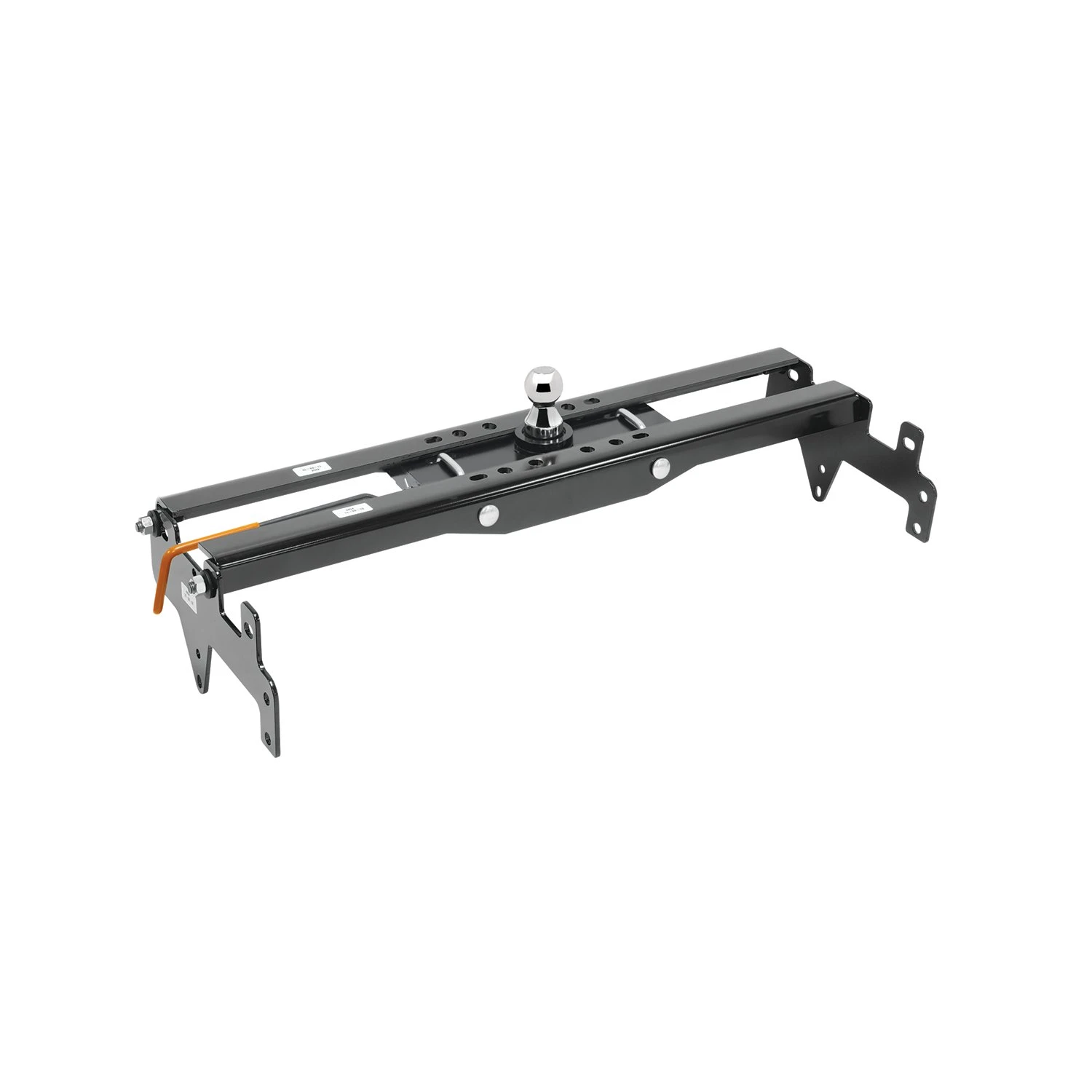
Quick Ship
In stock and ready to ship — order now!
FREE ShippingFREE SHIPPING
Estimated delivery Fri, Oct 16 - Mon, Oct 19
Order before 2 PM EST Monday–Friday for same-day processing
Guaranteed safe & secure checkout
No reviews have been added for this product.