
1980 - 1986 Ford F-350 Old body with 10" drop bumper Curt 2", Class 3 Trailer Tow Hitch + 4-flat Wiring Kit 13099CURTOriginal price was $548.90. Current price is $513.45.In Stock
View productOur in-house experts typically reply within one business day.

CURT
Verify Fitment
Select your vehicle to confirm this part fits.








Always the correct part
We know our products
Quality Products
Free Shipping!
Always the correct part
We know our products
Quality Products
Free Shipping!
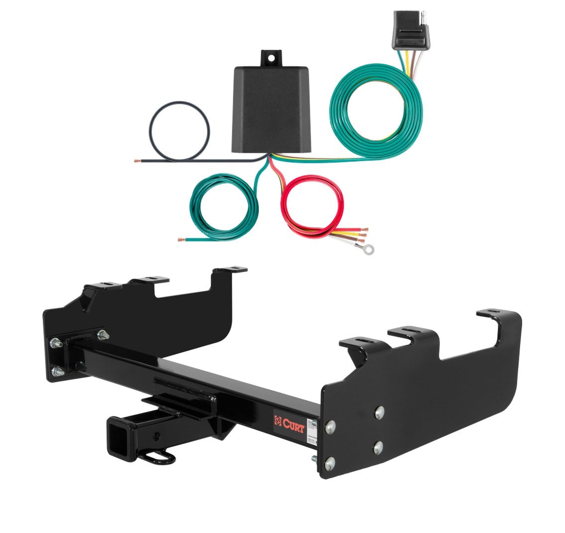
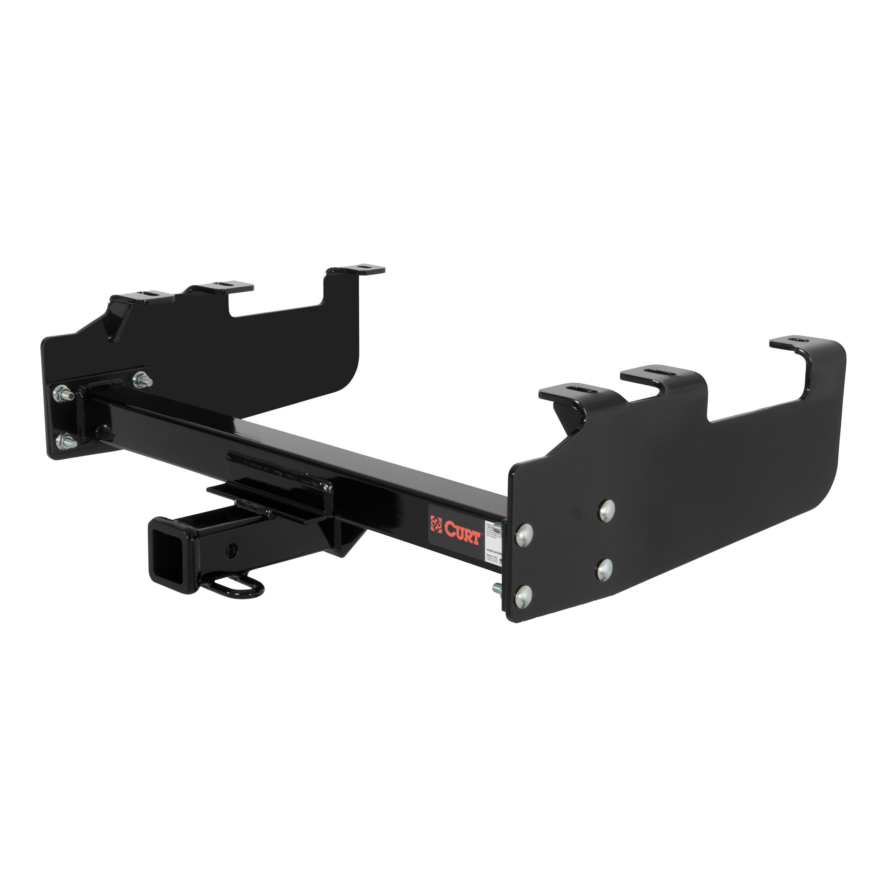
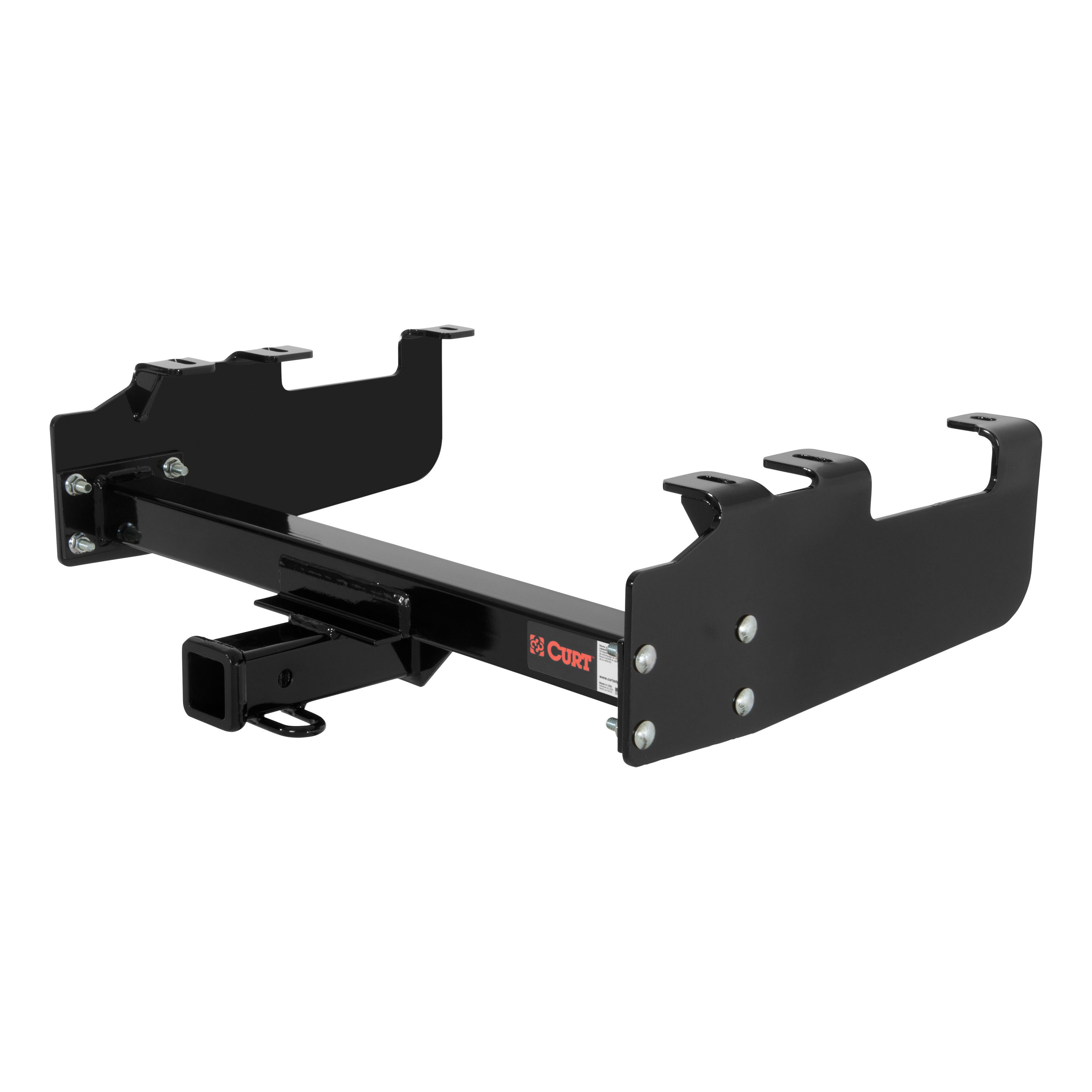
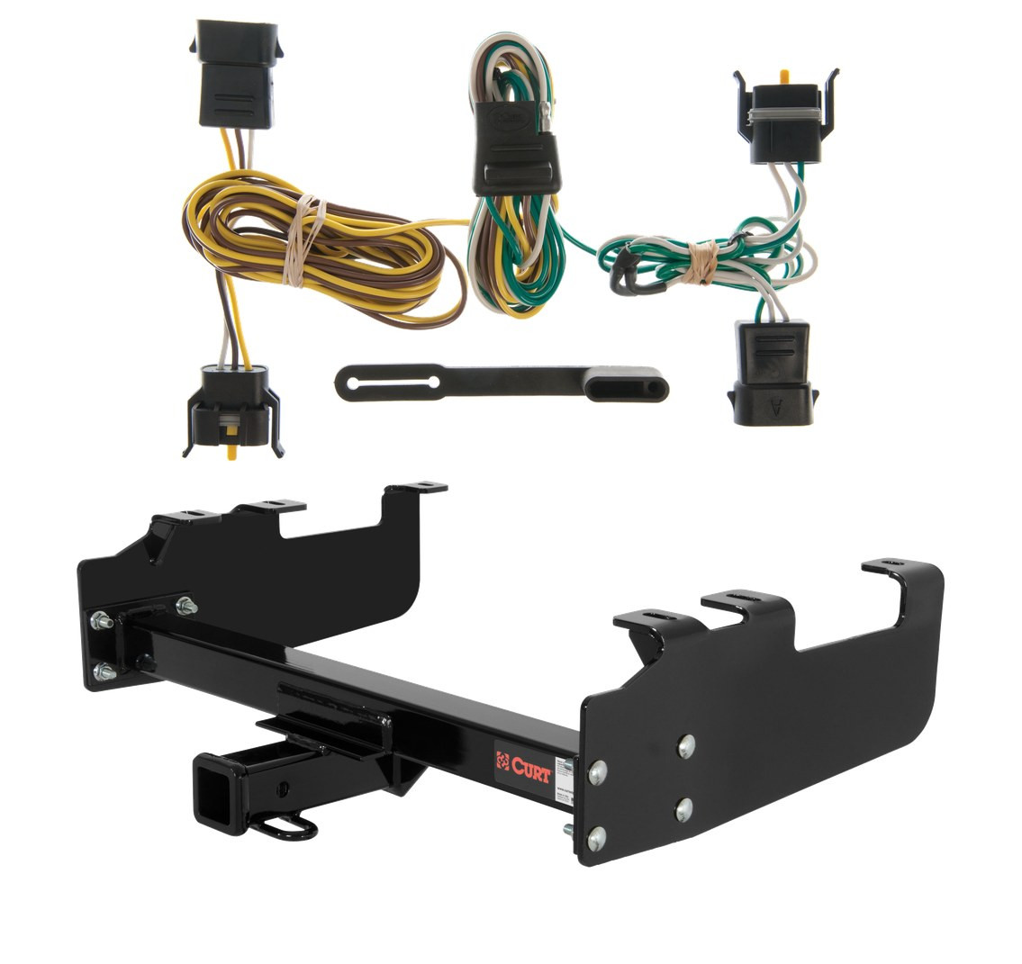
Complete CURT Class 3 2" trailer hitch and Universal Wiring Kit engineered for the 1980 - 1983 Ford F-100 With 10" drop bumper, old body. Vehicle-specific hitch fit, with a universal taillight converter for trailer wiring; all hardware and instructions included.
This custom kit fits the following vehicles:
All Hardware and Installation Instructions Included!
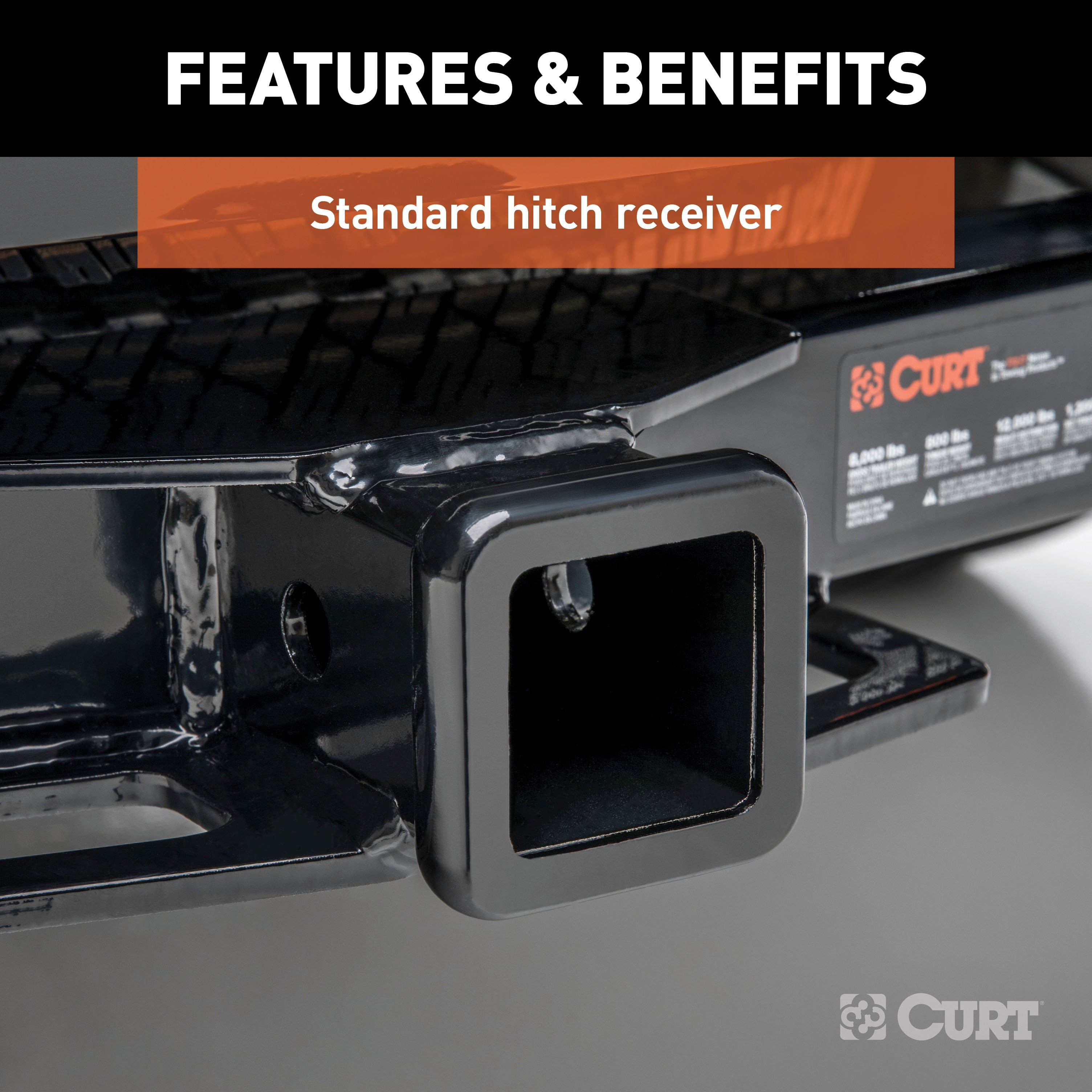
Whatever your task at hand -- whether it's launching that boat before daybreak, setting up your camper before the rush or getting a final load to the dump before close -- CURT class 3 trailer hitches offer the strength needed for serious towing. They make it easy to hitch up and Bring It, offering a vehicle-specific fit and the weight capacity to handle a variety of trailers. Custom class 3 hitches are the most common type of receiver hitch for pickup trucks and SUVs. Because of their weight range, they are also found on full-size cars, crossovers and minivans. Each custom-fit class 3 hitch package is made for vehicle-specific mounting. This particular kit fits older years of Ford, GMC and Chevy pickup trucks (see application info to verify vehicle compatibility). It provides a weight carrying capacity of 6,000 lbs. GTW and 600 lbs. TW. It is also compatible with a weight distribution hitch for level towing and a rating of 10,000 lbs. WD and 1,000 lbs. WDTW. CURT class 3 trailer hitches are typically used to attach and haul utility trailers, boat trailers, campers, snowmobile or ATV haulers and more (NOTE: Never exceed the lowest-rated towing component). Each class 3 hitch has a 2" receiver tube and is tested in accordance with SAE J684 for safety. To ensure that CURT class 3 receiver hitches have what it takes for serious trailering, they are designed using a hands-on approach and are constructed with rugged, high-strength steel and precise welding. We also protect our class 3 hitches in a co-cured finish of liquid A-coat and black powder coat for superior resistance to rust, chipping and UV damage.
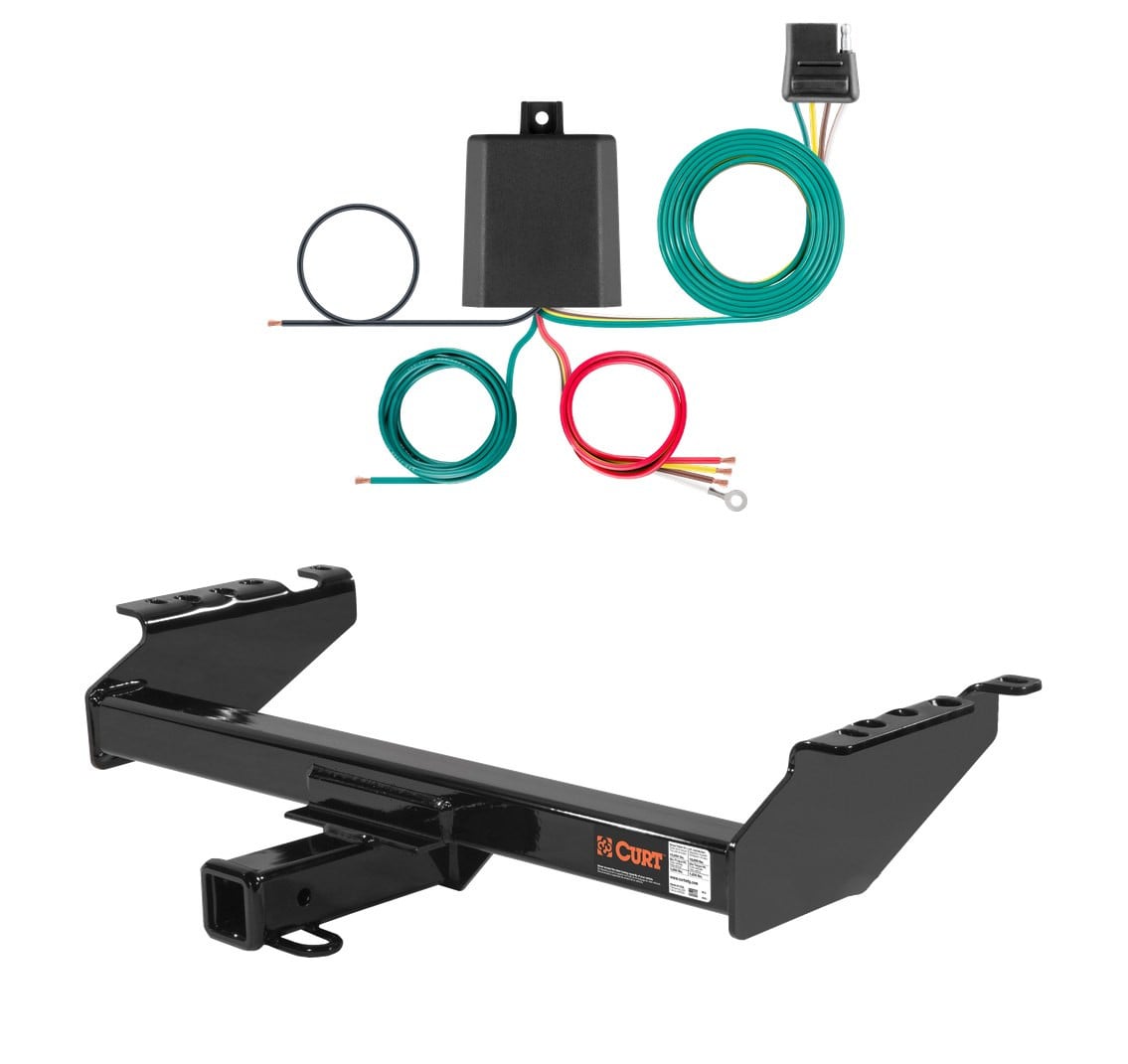
This CURT universal taillight converter is the go-to solution when a vehicle-specific custom harness isn't available for your make and model. It provides a standard 4-way flat trailer connector for tail lights, brake lights and turn signals, and is compatible with most vehicles (light splicing required). Built with surface-mount circuitry and a potted enclosure for durability against moisture, vibration and road debris. Includes a dust cover and is backed by a limited one-year warranty.

CURT offers a variety of high-quality trailer hitches and accessories for select vehicle models. Find the perfect fit for your towing needs at TowUniverse.
CURT, a Lippert brand, offers a complete line of towing products and is the leading manufacturer of custom-fit trailer hitches. We offer the broadest selection of custom-fit hitches, and each one is designed, welded, and coated in Wisconsin.
CURT is also a leader in flat towing products, as well as 5th wheel, gooseneck, and weight distribution hitches, ball mounts, electrical components, cargo solutions, and other towing accessories.
For everything from passenger cars and vans to full-size pickups and SUVs, CURT is 'The First Name in Towing Products®.'

Experts available to answer your questions
Call 888-634-94941 compatible vehicles
| Year | Make & Model | Notes |
|---|---|---|
| 1980 - 1983 | Ford F-100 | With 10" drop bumper, old body |
The 80 - 83 Ford F-100 With 10" drop bumper, old body Curt 2", Class 3 Trailer Tow Hitch + 4-flat Wiring Kit 13099 (Part #CHW-1009) fits the following vehicles: 1980-1983 Ford F-100. Always verify your specific year, make, and model before ordering.
Yes, the 80 - 83 Ford F-100 With 10" drop bumper, old body Curt 2", Class 3 Trailer Tow Hitch + 4-flat Wiring Kit 13099 (Part #CHW-1009) is designed to fit the 1980-1983 Ford F-100.
The 80 - 83 Ford F-100 With 10" drop bumper, old body Curt 2", Class 3 Trailer Tow Hitch + 4-flat Wiring Kit 13099 (Part #CHW-1009) fits 1980-1983 Ford F-100 models. The 1983 model year is the last year covered by this part number. For newer models, check for an updated version.
The 80 - 83 Ford F-100 With 10" drop bumper, old body Curt 2", Class 3 Trailer Tow Hitch + 4-flat Wiring Kit 13099 (Part #CHW-1009) Refer to the included instructions for installation details. Basic hand tools are typically all you need.
Yes, part number 13099 is designed for 1963–1996 Ford Trucks (all full size, old body style only). Your 1985 F-150 is within this range and should be compatible.
Yes, part number 13099 is compatible with 1970–2000 Chevrolet & GMC Pickup (full size with 10" step bumper). Your 1995 C1500 is within this range, provided it has a full-size frame and a 10" step bumper.
No. Part number 13099 is designed only for 1963–1996 Ford Trucks (all full size, old body style only). It is not compatible with Ford trucks manufactured after 1996.
The manual specifies compatibility with 1970–2000 Chevrolet & GMC Pickup (full size with 10" step bumper). If your vehicle does not have a 10" step bumper, compatibility is not confirmed by the manual. Contact Curt Manufacturing or a fitment specialist to verify.
The kit includes: 6× 1/2–13 UNC carriage bolts, 1–3/4" long (part 10-10272); 6× 0.250 × 1.50 × 2.00" square hole spacers (CM-SP1); 6× 1/2–13 UNC serrated flange nuts (part 20-00062); 8× 7/16–14 UNC serrated flange nuts (part 20-00103); and 8× 7/16–14 UNC carriage bolts, 1–1/2" long (part 10-10282).
Yes. Step 1 of the installation instructions requires you to remove the spare tire from the vehicle before beginning installation. Note that the spare tire carrier may need to be relocated and/or modified to retain under-vehicle tire stowage after the hitch is installed. On some Ford Pickup models with a 16" spare tire, the spare tire cradle may also require adjustment.
Yes. Step 2 requires you to measure the vehicle frame width. The bracket orientation depends on frame width: for 34" frames, position the side bracket with mounting flanges pointing inboard; for 38" frames, position the bracket with mounting flanges pointing outboard.
Yes, drilling is required. Step 4 requires you to drill six 17/32" diameter holes in the vehicle frame using the slotted holes in the bracket as a guide. The manual recommends starting with a smaller bit and working up to 17/32". In some cases, it may be possible to use existing holes in the frame instead of drilling new ones.
Drill six 17/32" diameter holes in the vehicle frame. The manual recommends starting with a smaller bit and working up to 17/32" to ensure accuracy. Use the slotted holes in the bracket as a guide for hole placement.
Torque all 1/2" fasteners to 110 lb.-ft. and all 7/16" fasteners to 70 lb.-ft. These torque values are applied after the crosstube assembly is installed into the side brackets and all fasteners are hand-tightened.
No. Step 5 instructs you to install the side bracket mounting fasteners but explicitly states "Do not tighten at this time." The fasteners are tightened to final torque (110 lb.-ft. for 1/2" fasteners) only after the crosstube assembly is installed and all fasteners are in place (Step 7).
The crosstube assembly is attached using 7/16" × 1–1/2" carriage bolts and 7/16" serrated flange nuts (part 20-00103). Eight of each fastener are included in the kit. These fasteners are torqued to 70 lb.-ft. after installation.
The six 0.250 × 1.50 × 2.00" square hole spacers (part CM-SP1) are installed inside the vehicle frame when mounting the side brackets. They are placed between the frame and the bracket mounting fasteners to ensure proper spacing and load distribution.
Do not exceed your vehicle manufacturer's recommended towing capacity. The hitch has its own capacity ratings (weight-carrying and weight-distribution modes), but the manual emphasizes that the vehicle's limit takes precedence. Consult your vehicle's owner manual for the maximum towing capacity.
Periodically check the receiver hitch to ensure that all fasteners are tight and that all structural components are sound. The manual does not specify an exact interval, but regular inspection before towing is recommended to maintain safety and warranty coverage.
1963–1996 Ford Trucks (all full size, old body style only) and 1970–2000 Chevrolet & GMC Pickup (full size with 10" step bumper).
Yes. You must drill six 17/32" diameter holes in the vehicle frame. The manual recommends starting with a smaller bit and working up to 17/32". Existing frame holes may be reused if available.
Six 1/2–13 UNC carriage bolts, six square hole spacers, six 1/2–13 UNC flange nuts, eight 7/16–14 UNC flange nuts, and eight 7/16–14 UNC carriage bolts.
Torque all 1/2" fasteners to 110 lb.-ft. and all 7/16" fasteners to 70 lb.-ft.
Periodically check all fasteners to ensure they are tight and inspect all structural components for soundness.
The CURT taillight converter (56496) is a module that converts a vehicle's taillight wiring to a 4-flat trailer connector. It allows you to connect a trailer with a 4-flat plug to vehicles that do not have a factory trailer connector. The converter interprets your vehicle's existing taillight signals (brake, turn, and tail lights) and outputs them through the 4-flat connector to power the trailer lights.
The converter is designed for SUVs, mini and full-sized vans, passenger cars, and pickup trucks. The manual provides wiring location guides for three vehicle categories: SUVs/vans (S-series locations), passenger cars (P-series locations), and pickup trucks (T-series locations). However, the manual does not provide a specific year, make, or model compatibility list. Contact CURT or consult a fitment database to confirm compatibility with your specific vehicle.
The converter is designed only for 12-volt negative ground electrical systems. Before purchasing, confirm your vehicle uses a 12-volt negative ground system. If your vehicle uses a different voltage or positive ground system, this converter will not work. Check your vehicle owner's manual or contact the vehicle manufacturer to verify your system type.
Included with the converter: snap locks, double-sided tape, cable ties, ground screw, and white ground wire with ring terminal. You must source separately: 12 gauge wire (or larger), 10-amp fuse (maximum), fuse holder, butt connectors, and ring terminal. Alternatively, CURT part 55151 is a kit that includes these items. Tools needed: multimeter or test light for wiring identification, wire strippers, and a drill with 3/32" bit (if drilling a ground hole is necessary). A socket wrench or screwdriver may be needed to disconnect the battery terminal.
Yes. Step 3 of the installation instructions requires you to locate the vehicle battery and disconnect the negative battery terminal before wiring the converter. The negative terminal must remain disconnected until Step 7, after all wiring is complete and the fuse is installed. This prevents electrical shorts and damage during installation.
The manual provides a 'How to Determine Vehicle Wiring Types' procedure on page 2. With the vehicle running and all lights off, probe the taillight connectors (still connected to the vehicle) using a multimeter set to DC volts or a test light. Wires carrying less than 2 volts (or that do not illuminate a test light) are not used. Then activate each light circuit (left turn, right turn, tail, brake) one at a time and probe the remaining wires to identify which wires carry which signals. This determines whether your vehicle has a two-wire system (combined stop/turn with independent tail) or three-wire system (independent stop, turn, and tail signals). This information is essential for correctly splicing the converter wires in Step 4.
Mount the converter near the taillight. The manual provides a wiring location guide showing eight possible locations for SUVs/vans (S1–S8), seven for passenger cars (P1–P7), and five for pickup trucks (T1–T5). These locations are behind taillight housings, rear bumpers, rear access panels, or under rear floor panels, depending on vehicle type. Once you have selected the location, adhere the black converter box using the provided double-sided tape and secure it with the included cable ties. Ensure the area is clean and dry before applying the tape.
In Step 4, use snap locks to attach the converter's input wires to the corresponding vehicle harness wires. The converter has four input wires: red (brake), yellow (left turn), green (right turn), and brown (tail). The wiring installation table on page 3 shows which converter wire splices to which vehicle wire, depending on whether your vehicle has a two-wire or three-wire system. For a two-wire system: green splices to the right stop/turn wire, yellow to the left stop/turn wire, brown to the tail wire, and red is grounded. For a three-wire system: green splices to the right turn wire, red to the stop wire, yellow to the left turn wire, and brown to the tail wire. Photos A, B, and C on page 3 show how to install the snap locks.
In Step 6, locate a suitable grounding point near the taillight. The white ground wire has a ring terminal attached. If an existing screw with nut is available in the vehicle frame, attach the ring terminal to that screw. If not, drill a 3/32" pilot hole in a clean, rust-free, paint-free area of the vehicle frame and use the provided screw to secure the ring terminal. Before drilling, check for hidden items behind or under surfaces to avoid damage and personal injury.
Route 12 gauge wire (or larger) from the converter's black power wire to the vehicle battery positive (+) terminal, taking care to avoid pinch points and hot or rotating components. At the battery, use a ring terminal (not included) to attach the wire to the positive post. Install a 10-amp fuse (maximum) in a fuse holder (not included) on this power wire, positioned as close to the battery as possible. Install the fuse only after all other wiring steps are complete. The negative battery terminal must remain disconnected until the fuse is installed.
In Step 7, secure any loose wires with the provided cable ties. This prevents wires from moving, chafing, or becoming pinched during vehicle operation. Route the 4-flat connector to the center of the vehicle when in use, and secure it in a convenient out-of-the-way location when not in use.
The converter is rated for a maximum of 3.0 amps per signal circuit (left turn, right turn, brake) and 6.0 amps total for tail and running circuits. Do not exceed these ratings. Also do not exceed your tow vehicle's lamp load rating, whichever is lower. Exceeding the product rating can cause loss of warranty, overheating, and potential fire.
The battery connection must be fuse-protected with a 10-amp maximum fuse. Do not use a fuse larger than 10 amps. The fuse holder and fuse are not included and must be purchased separately, or as part of CURT part 55151 kit. Install the fuse after all other wiring steps are complete and immediately before reconnecting the negative battery terminal.
Use 12 gauge wire or larger to route from the converter's black power wire to the vehicle battery. This wire must be routed carefully to avoid pinch points and hot or rotating components. The wire is not included and must be purchased separately, or as part of CURT part 55151 kit.
The converter has four input wires: red (brake signal), yellow (left turn signal), green (right turn signal), and brown (tail/running light signal). There is also a white ground wire with a ring terminal. Each input wire is spliced to the corresponding vehicle taillight wire using snap locks, according to your vehicle's wiring type (two-wire or three-wire system). The black power wire connects to the vehicle battery positive terminal through a fused connection. The white ground wire connects to the vehicle frame or body.
Before drilling any holes, check for miscellaneous items (wires, fuel lines, brake lines) that may be hidden behind or under surfaces to avoid damage and personal injury. Disconnect the negative battery terminal before beginning any wiring work. When routing the power wire to the battery, avoid pinch points and hot or rotating components. Ensure the area where you ground the converter is free of rust, dirt, and paint. Do not exceed the converter's amperage rating (3.0 amps per signal circuit, 6.0 amps total for tail/running) or your vehicle's lamp load rating, as this can cause overheating and fire. Use a 10-amp maximum fuse on the battery connection.
The manual provides two testing methods. Method 1 (test light): Attach the ground lead of the tester to the exposed ground terminal of the 4-flat connector. Activate the tow vehicle's left turn, right turn, tail, and brake lights one at a time. Probe the three receptacles of the 4-flat to confirm proper functionality. Method 2 (trailer): Mate the 4-flat with a trailer and run the same test using the trailer lights. If a function on the trailer lights does not work, disconnect the trailer 4-flat, turn the vehicle functions off, and recheck with a circuit tester. If the circuit tester shows the function is good, the problem is with the trailer, not the converter.
Included: snap locks, double-sided tape, cable ties, ground screw, and white ground wire with ring terminal. Not included: 12 gauge wire, 10-amp fuse, fuse holder, butt connectors, and ring terminal for the battery connection. These items must be purchased separately or as part of CURT part 55151 kit, which is sold separately.
After securing all loose wires with cable ties and installing the fuse on the battery power wire, reinstall all items you removed during installation (trim panels, bumpers, etc.). Reconnect the negative battery terminal. When the converter is in use, route the 4-flat connector to the center of the vehicle. When not in use, secure the connector in a convenient out-of-the-way location to prevent damage.
The converter fits SUVs, vans, passenger cars, and pickup trucks with 12-volt negative ground systems. The manual does not provide a specific year/make/model list. Contact CURT or check a fitment database with your vehicle details to confirm compatibility.
You must source: 12 gauge wire, 10-amp fuse, fuse holder, butt connectors, and a ring terminal for the battery. These are available separately or as CURT part 55151 kit.
Yes. Disconnect the negative battery terminal in Step 3 before wiring, and keep it disconnected until the fuse is installed in Step 7.
Drilling may be required. If a suitable existing screw is not available near the taillight for grounding, you must drill a 3/32" pilot hole in the vehicle frame. Before drilling, check for hidden items (wires, fuel lines) behind or under surfaces to avoid damage.
Maximum 3.0 amps per signal circuit and 6.0 amps total for tail/running circuits. Do not exceed these ratings or your vehicle's lamp load rating, whichever is lower.
Before drilling, check for hidden items (wires, fuel lines, brake lines) behind or under surfaces to avoid damage and personal injury.
Disconnect the trailer 4-flat connector from the converter. Turn off the corresponding function on the vehicle (e.g., turn off the left turn signal if the left turn on the trailer is not working). Recheck the function using a circuit tester on the 4-flat receptacles. If the circuit tester shows the function is working properly, the problem is with the trailer, not the converter. If the circuit tester shows the function is not working, the converter or vehicle wiring connection may be faulty.
On Sale Today
Original price was $548.90. Current price is $513.45.You save $35.45 (6%)
Free Shipping
Ships free on all orders
 Authorized Dealer
Quick Ship
In stock and ready to ship — order now!
FREE ShippingFREE SHIPPING
Estimated delivery Wed, Sep 23 - Sat, Sep 26
Order before 2 PM EST Monday–Friday for same-day processing
Guaranteed safe & secure checkout


Total for 4 items:
$618.45$656.41
No reviews have been added for this product.