
Air Lift LoadController (Compact, Single Path, Heavy Duty) 25854Air LiftOriginal price was $561.99. Current price is $407.99.In Stock
View productOur in-house experts typically reply within one business day.

Air Lift



Always the correct part
We know our products
Quality Products
Free Shipping!
Always the correct part
We know our products
Quality Products
Free Shipping!
Offering quick and convenient air pressure adjustment, LoadController (Compact, Dual Path, Heavy Duty) will have your vehicle back on the level in no time, eliminating the need to hunt for a gas station with an air compressor!

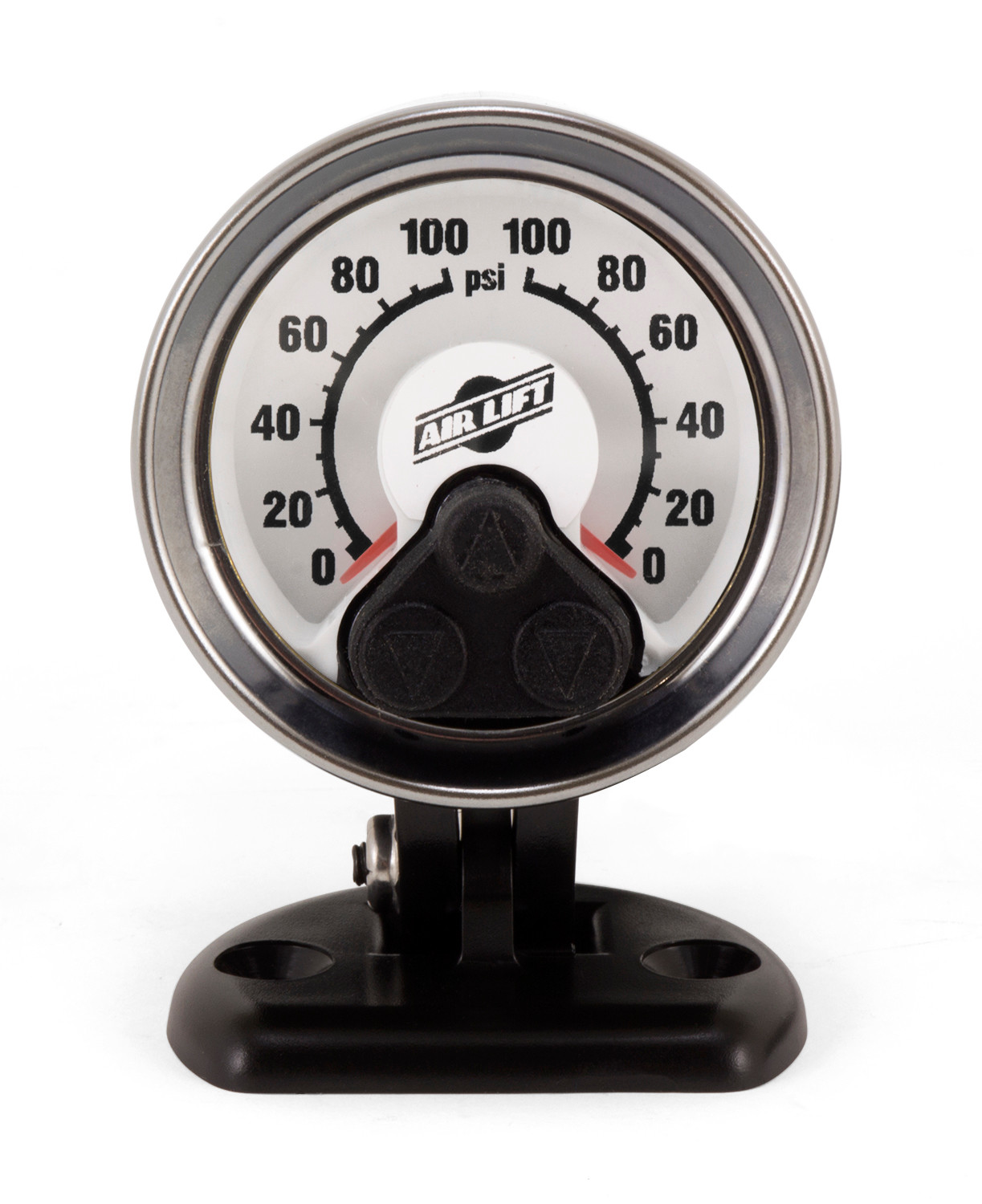
Offering quick and convenient air pressure adjustment, LoadController (Compact, Dual Path, Heavy Duty) will have your vehicle back on the level in no time, eliminating the need to hunt for a gas station with an air compressor! LoadController allows you to control the pressures of your air springs with the touch of a button, whether parked or on the road. There's no need to worry about changes in load or road conditions -- you can make on-the-go changes from inside the cab. With an exclusive low pressure sensor that automatically activates if pressure drops to an unsafe level, you can be sure that your vehicle and load are protected, no matter what the road throws at you. The easy-to-read, user-friendly pressure gauge features both inflate and deflate buttons, allowing users to users to quickly make changes in air pressure. LoadController is a dual path system, meaning that the air springs can be independently adjusted to different pressures, perfect for uneven loads. Dual path systems help to prevent air transfer between air springs, which provides a more stable cornering situation and significantly less body roll. The mounting pod is customizable to your preferences, with the ability to be mounted in the included mounting cup, flush mounted into the dash, or inserted into any 2 1/8 in. gauge pod. With the included, pre-assembled wiring harness, you'll be able to have your vehicle level and on the road in only a matter of hours. The heavy-duty compressor, perfect for frequent users of the system, mounts easily to the vehicle's frame and the routes the air line directly to the air springs. With the included, fully-illustrated installation manual provides clear instructions to make installation a breeze. As the leader in air suspension products for over 70 years, Air Lift is committed to delivering quality parts that last.
Air Lift Company has developed dependable air spring suspension products since our inception in 1949. Our original product, a rubber air spring inserted into a car’s factory coil spring, was created and patented in 1950. We’ve come a long way since 1949 and are proud to be a dedicated suspension specialist company.
Today, Air Lift load support products are sold worldwide and are engineered to fit over 540 vehicles. Our extensive product line offers air helper springs for trucks, RVs, SUVs, CUVs, and vans, as well as the most technologically advanced on-board air compressor systems for on-the-go air spring control.
Air Lift leads the industry in no-drill applications – kits that bolt onto your vehicle’s frame, speeding the installation process. Our teams work constantly to bring innovative products to you and upgrade existing products with the latest technology.
All of our efforts are spent ensuring your safety and comfort by designing, engineering, and manufacturing the highest quality suspension products. We are a family-owned business based in Lansing, Michigan, and make your family and cargo’s safety our top priority.
Experts available to answer your questions
Call 888-634-94942 Years
The Load Controller / Dual is an onboard air management system designed to work with Air Lift air spring kits. It includes a dual analog gauge, compressor, low pressure sensors, and control electronics. The system automatically maintains minimum air pressure in the air springs (preset to 5 PSI unless adjusted) and allows manual inflation to support vehicle load. It protects air springs from failure due to low pressure in the unloaded condition.
The Load Controller / Dual is compatible with Air Lift LoadLifter 5000, Air Lift 1000, and Ride Control air spring applications. If adding this control system to an Air Lift LoadLifter 5000 application, no modifications to the low pressure sensor are necessary. If adding to Air Lift 1000 or Ride Control applications that require a minimum of 10 PSI, the low pressure sensor must be adjusted from the factory 5 PSI setting.
Only if your specific application requires a minimum of 10 PSI. If it does, you must adjust the low pressure sensor from its factory preset of 5 PSI. To adjust: remove the rubber plug with pliers, use an allen wrench to turn the screw clockwise 4 1/4 turns, then push the rubber plug back in. No adjustment is needed for Air Lift LoadLifter 5000 applications.
Required tools include: pliers (to remove rubber plug from low pressure sensor), allen wrench (to adjust low pressure sensor), hose cutter (to cut existing air lines), 7/16" nut driver (for standard duty compressor mounting in some cases), drill with 13/64" bit (for standard duty compressor frame mounting), drill with 1" bit (for firewall/floorboard grommet hole), and crimp tool (for electrical connectors). A circular motion tool or lubricant may assist with pushing air lines onto barbed fittings.
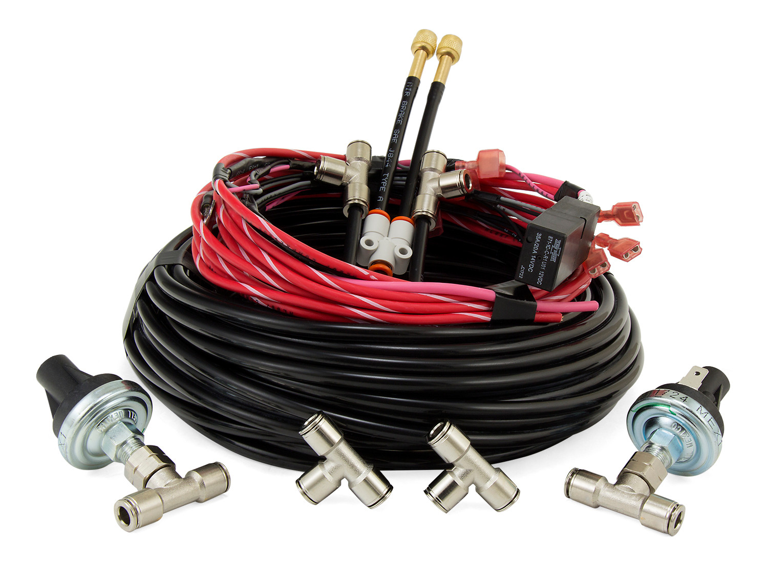
The kit includes: analog dual gauge (25195), harness (26918), two 5 PSI low pressure sensors (26042), 50 feet of 1/4" DOT air line (20946), gauge mounting kit (25196), grommet (10463), 15 amp spade fuse (24652), fuse holder (24539), two butt connectors (24752), three fuse adapters for different fuse types (24543, 24561, 24542), terminal connectors in various sizes (24524, 24594, 24595, 24592), five 8" zip ties (10466), two tee unions (21838), two #8-18X1" tek screws (24539), Y-assembly (26061A), and two tee fittings with check valves (21275). Choose the compressor separately: standard duty (16060) or heavy duty (16192).
The compressor must be located in a dry, protected area on the vehicle, shielded from direct splash and excessive moisture, which can damage the compressor and cause system failure. Avoid high heat environments and do not mount under the hood. If mounting outside the vehicle, the compressor body must be shielded from direct splash and the intake should be snorkeled inside the vehicle. Orient the compressor intake filter so moisture can easily drain. The compressor can be mounted in any position: vertical, upside down, sideways, etc. Verify that compressor harness #2 will reach the compressor and connect to harness #1.
Yes. The installation guide states that the air spring kit should be installed first per the instructions provided with the air spring kit. The Load Controller / Dual installation should be done after the air spring kit is installed.
Select a convenient mounting location with a sturdy rigid surface. The bottom edge of the dash on either side of the steering wheel is recommended. Attach the gauge pod to the selected location using the black self-tapping screws provided. An optional dash mounting bracket and hardware are also included if preferred.
Connect the color-coded wires to the gauge harness as shown in the electrical schematic (figure 2). Connect the low pressure switch assemblies as shown in the same schematic. Do not connect the power wire at this time. The wiring harness also connects the gauge pod to the low pressure sensor assembly, which should be located under the dash inside the vehicle and secured with the provided tie straps. Screw the ground eyelet to the firewall or other electrical ground in the cab.
Drilling may be required depending on compressor type and mounting location. For standard duty compressor mounting on box frames where the frame section is not wide enough to mount the compressor legs flat to the rail, you may need to drill 13/64" holes through the frame and use a 7/16" nut driver to install self-tapping screws. For heavy duty compressor mounting, drill holes using the compressor as a template and mount using the black mounting hardware provided. If routing the harness through the firewall or floorboard requires a new hole, drill a 1" diameter hole and install the provided grommet. Always check for hydraulic lines, gas lines, and electrical wires before drilling.
Do not drill any holes into the frame or floorboard before checking for hydraulic lines, gas lines, and electrical wires that may need to be moved aside. When attaching to the floorboard, check where the screws protrude through the floorboard on the inside of the vehicle. It may be necessary to trim or cover the top of the screws inside the vehicle. A sealer should be used around the screw to prevent elements from entering the cab area. All drilled holes and grommets must be sealed to prevent elements from entering the cab.
Hold the compressor in the recommended location. For box frames where the frame section is not wide enough to mount the compressor legs flat to the rail, use an L-bracket as shown in figure 11. In some cases, the mounting area may not provide enough room to use a drill to drive in the screws. If so, use the mounting brackets as a template to drill 13/64" holes through the frame first, then use a 7/16" nut driver to install the self-tapping screws. Attach the compressor ground wire to one of the mounting screws.
Using the compressor as a template, drill holes and mount the compressor using the black mounting hardware that comes in the box containing the compressor. Attach the compressor ground wire to one of the mounting screws.
Push the air line onto the barb fitting on the compressor. Make sure the air line covers all barbs. A small amount of water or lubricant and pushing with a slight circular motion will ease installation.
Remove the nut from the leader line and install it over the air line from the check valve assembly. Push the air line from the check valve assembly into the barbed fitting on the compressor leader line. Slide the nut over the fitting and tighten securely.
Use existing grommets in the floorboard or firewall to route the harness from the cab to the frame-mounted compressor. In some cases, a hole may have to be drilled to allow access for the harness. Drill a 1" diameter hole and install the provided grommet. It will be necessary to seal any grommets or holes that have been cut, drilled, or removed so as not to allow elements to enter the cab area. When routing the wiring harness, it should not be routed so as to lay on or near the exhaust pipe, muffler, or catalytic converter. Routing along the top of a crossmember or over a heat shield is recommended.
With the air springs deflated, use a hose cutter to cut the air line already installed between the air springs and the inflation valves. Install the provided tee fittings by pushing the air line into each leg of the tee until you feel a definite click. Each line should go in 9/16". Connect a single length of air line to the open leg of the tee. Connect as shown in the pneumatic schematic. Route the air line across the chassis from the far side over the exhaust system heat shields and along the frame up to the compressor. Avoid heat sources, sharp edges, and tight bends. Route air lines into the cab from the tee fitting and attach to the pressure switch assembly as shown in the pneumatic schematic. Route air lines from the low pressure switch to the gauge barb and press the air line over the gauge barb. Water or lubricant may assist in securing air lines over the barb; a circular motion will assist in installation.
Route the power wire to the vehicle fuse box. Determine which open terminal (accessory, etc.) works only when the key is in the "on" or accessory position, or refer to the owner's manual for an available accessory fuse. The terminal should have an amperage rating higher than the 15 amp in-line fuse. Connection to the fuse terminal depends on the type of fuse your vehicle uses. If your vehicle uses barrel type fuses, use adapter #1 (24543). If you have standard spade type fuses, use adapter #2 (24561). Many late model vehicles use a smaller spade type fuse which requires adapter #3 (24542). If using adapter #1 or #2, crimp on a 1/4" (14-16GA) female connector. If using adapter #3, crimp on a 3/16" (14-16GA) female connector. The harness comes with blunt cut wire so no cut-off is necessary; just crimp the wire right to the connector. Connect the adapter to the "HOT" side of the fuse.
The system uses a 15 amp in-line fuse (part number 24652). When connecting to the vehicle fuse box, the terminal should have an amperage rating higher than 15 amps.
Never run the compressor longer than 4 minutes continuously. Allow at least 5 minutes for cool-down before starting the compressor again.
Inflate to 30 PSI (2.07 BAR) for most applications. For Air Lift 1000 kits, inflate to 20 PSI (1.4 BAR). Use the on/off button to inflate both air springs and the small deflate button to adjust the pressure.
After inflating the air springs, check all fittings and inflation valve cores with a solution of 1/5 dish soap to 4/5 water in a spray bottle for leaks. If the compressor runs continually or often, there is a leak. Disconnect the compressor at the fuse box and test for leaks with a soapy water solution.
No. The installation of this kit does not alter the Gross Vehicle Weight Rating (GVWR) or payload of the vehicle. You must check your vehicle's owner's manual and not exceed the maximum load listed for your vehicle. GVWR is the maximum allowable weight of the fully loaded vehicle (including passengers and cargo), shown on the vehicle's Safety Compliance Certification Label. Payload is the combined maximum allowable weight of cargo and passengers, calculated as GVWR minus the Base Curb Weight.
The low pressure sensor protects the air springs from failure resulting from low pressure in the unloaded condition. It is preset to maintain a minimum pressure of 5 PSI in the air springs unless the setting was changed in the Getting Started section. The sensor measures the pressure in each spring and turns on the compressor if the pressure falls below the set PSI. The sensor should be located under the dash inside the vehicle and secured with the provided tie straps.
The Load Controller / Dual is compatible with Air Lift LoadLifter 5000, Air Lift 1000, and Ride Control air spring kits. If you have an Air Lift 1000 or Ride Control kit that requires 10 PSI minimum, you must adjust the low pressure sensor from its factory 5 PSI setting.
Yes. The kit includes all control components but not the compressor. You must choose either the standard duty compressor (part 16060) or heavy duty compressor (part 16192) separately.
Drilling may be required depending on your compressor type and mounting location. Standard duty compressor mounting may require drilling 13/64" holes in the frame. Heavy duty compressor mounting requires drilling holes using the compressor as a template. If the harness cannot route through existing grommets, you must drill a 1" hole for the provided grommet. Always check for hydraulic lines, gas lines, and electrical wires before drilling.
The system uses a 15 amp in-line fuse. Connection to your vehicle fuse box depends on your fuse type: barrel fuses use adapter #1, standard spade fuses use adapter #2, and smaller spade fuses use adapter #3. The vehicle fuse terminal must be rated higher than 15 amps.
Mount the compressor in a dry, protected area shielded from direct splash and moisture. Do not mount under the hood or in high heat environments. Verify the harness will reach from the cab to the compressor location. The compressor can be mounted in any position: vertical, upside down, or sideways.
Check all fittings and inflation valve cores with a solution of 1/5 dish soap to 4/5 water in a spray bottle. If the compressor runs continually or often, there is a leak; disconnect it at the fuse box and test with soapy water.
If the compressor runs continually or often, there is a leak in the system. Disconnect the compressor at the fuse box and test for leaks using a soapy water solution to identify the source.
Verify that the power wire is connected to the correct fuse terminal. The terminal should work only when the key is in the "on" or accessory position and should have an amperage rating higher than 15 amps. Ensure the adapter is connected to the "HOT" side of the fuse. Check that the 15 amp in-line fuse is not blown. With the ignition on, the compressor should turn on and fill the system to 10 PSI before shutting off.
On Sale Today
Original price was $855.99. Current price is $619.99.You save $236.00 (28%)
Free Shipping
Ships free on all orders
 Authorized Dealer
Quick Ship
In stock and ready to ship — order now!
FREE ShippingFREE SHIPPING
Estimated delivery Sat, Sep 26 - Tue, Sep 29
Order before 2 PM EST Monday–Friday for same-day processing
Guaranteed safe & secure checkout
No reviews have been added for this product.