
Air Lift LoadLifter 5000 Kit 57242Air LiftOriginal price was $667.99. Current price is $483.99.In Stock
View productOur in-house experts typically reply within one business day.

Air Lift
Verify Fitment
Select your vehicle to confirm this part fits.
2016 - 2023 Nissan TITAN XD
Confirmed to Fit

Always the correct part
We know our products
Quality Products
Free Shipping!
Always the correct part
We know our products
Quality Products
Free Shipping!
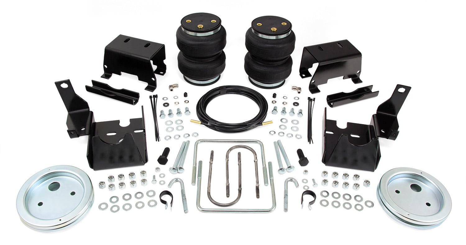
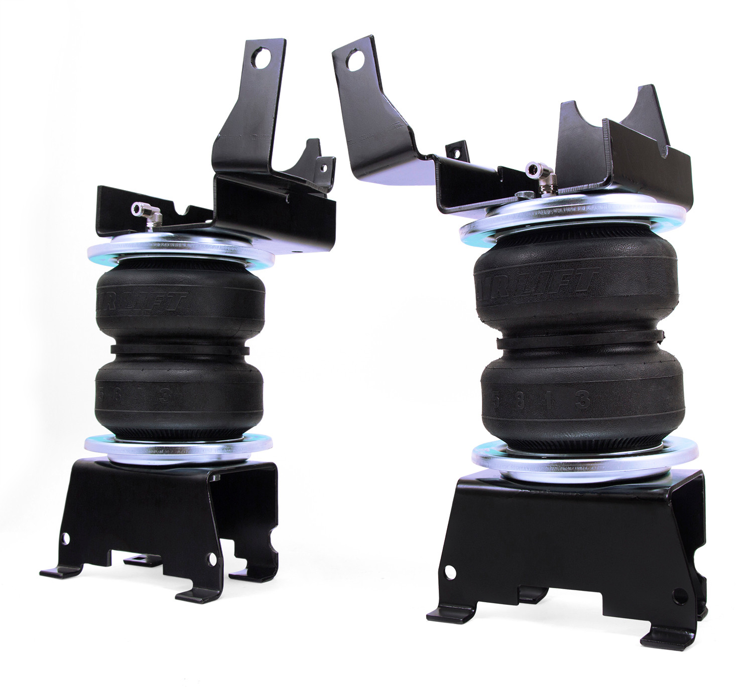
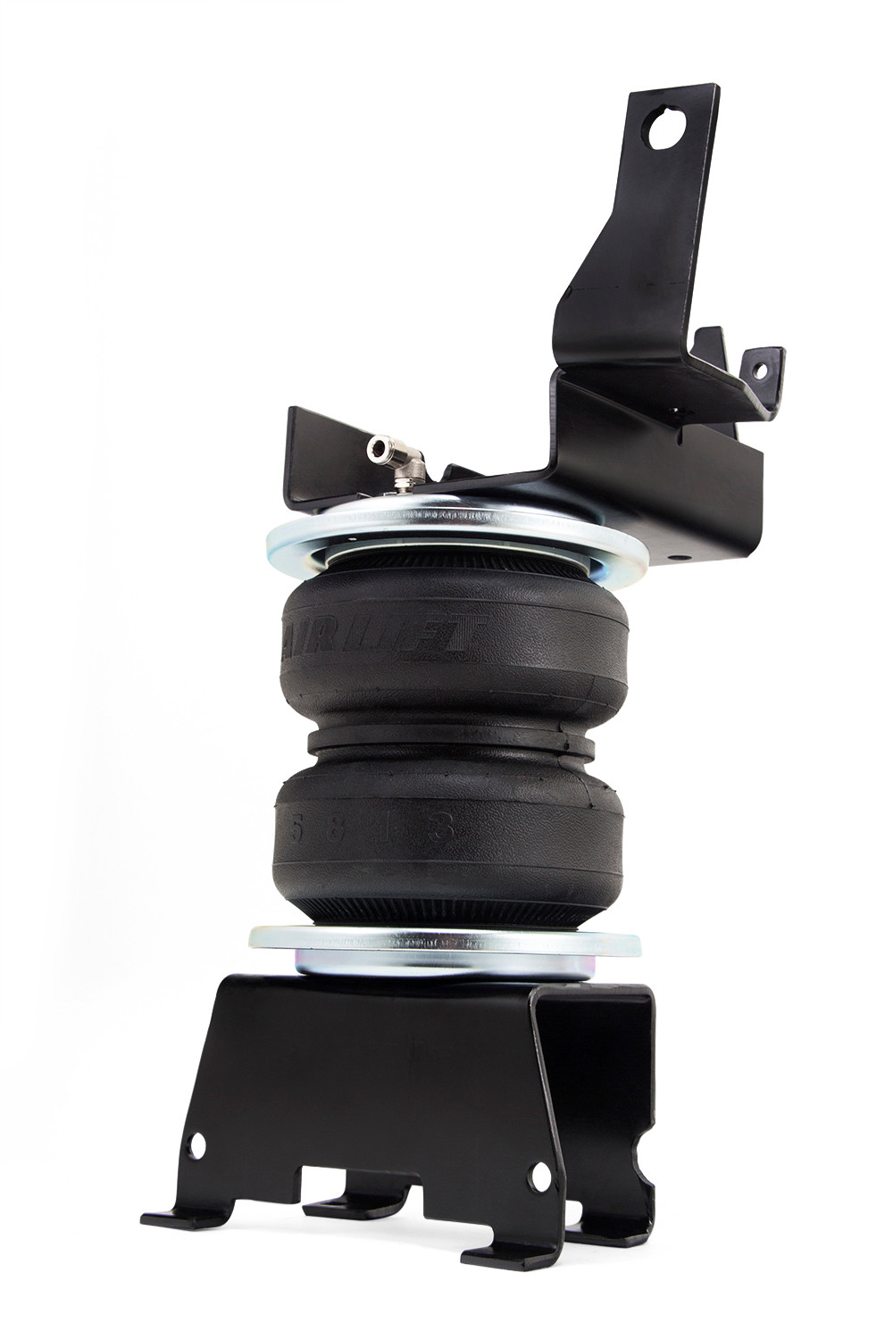
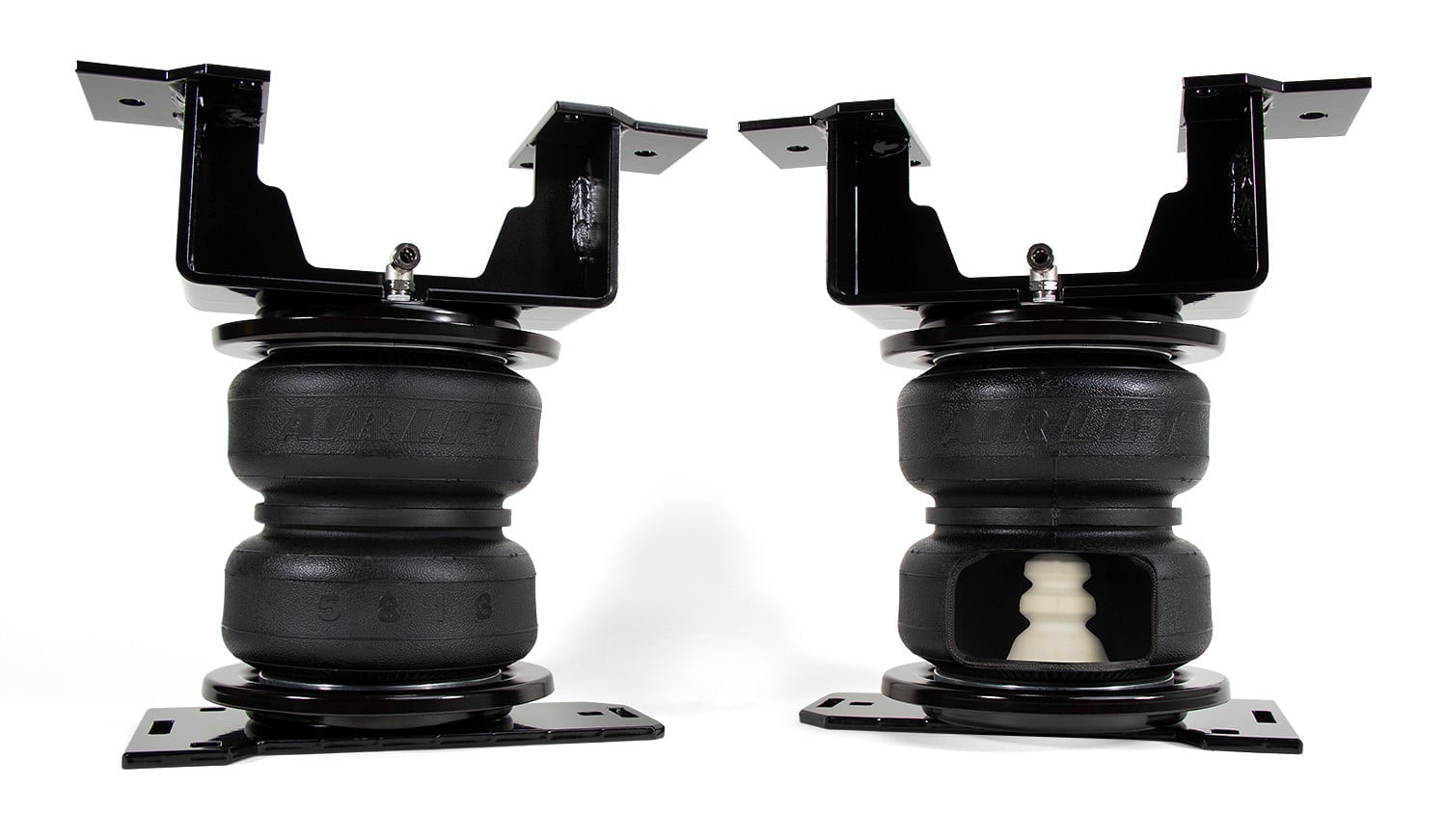
Offering up to 5,000 pounds of load-leveling capacity, the LoadLifter 5000 kit from Air Lift will make towing and hauling with your 2016-2021 Nissan Titan XD a breeze.

Offering up to 5,000 pounds of load-leveling capacity, the LoadLifter 5000 kit from Air Lift will make towing and hauling with your 2016-2021 Nissan Titan XD a comfortable and stress-free experience. For frequent use, our fully-adjustable, industry leading air springs are the perfect partner for your vehicle, eliminating any issues that you might face. The LoadLifter 5000 kit helps to eliminate problems frequently faced when towing and hauling, such as squat, poor headlight aim, trailer sway, body roll, and bottoming out. With the added stability and weight-distribution that air springs provide, you can haul safely, knowing that you have optimal braking and steering control. With the ability to adjust the air pressure from 5-100 PSI, your Titan XD can be ready for any weight and any situation (Note: Do not exceed vehicle's GVWR). An Air LIft exclusive, each kit comes equipped with upper and lower roll plates, added to protect the air springs from sharp edges, while increasing the load capacity by 10%. The air springs themselves are built like a tire, reinforced with 2-ply fabric for maximum strength. All of the end caps are made with an ultra high-strength nylon composite formula, strong as steel but much lighter and corrosion proof. As the leader in air suspension products for over 70 years, Air Lift is committed to delivering quality load support parts that last. To ensure the highest quality, longevity, and customer satisfaction, the key suspension components, including the air springs and all hardware, have all been torture-tested to 1 million cycles on our hydraulic test rig. With a lifetime warranty and 60-Day Ride Satisfaction Guarantee -- not to mention the Air Lift reputation for great customer service and technical support, should you run into any snags in the installation process -- you can purchase this kit with peace of mind. Installing the kit is a simple process, requiring only common hand tools and no frame drilling.
Air Lift Company has developed dependable air spring suspension products since our inception in 1949. Our original product, a rubber air spring inserted into a car’s factory coil spring, was created and patented in 1950. We’ve come a long way since 1949 and are proud to be a dedicated suspension specialist company.
Today, Air Lift load support products are sold worldwide and are engineered to fit over 540 vehicles. Our extensive product line offers air helper springs for trucks, RVs, SUVs, CUVs, and vans, as well as the most technologically advanced on-board air compressor systems for on-the-go air spring control.
Air Lift leads the industry in no-drill applications – kits that bolt onto your vehicle’s frame, speeding the installation process. Our teams work constantly to bring innovative products to you and upgrade existing products with the latest technology.
All of our efforts are spent ensuring your safety and comfort by designing, engineering, and manufacturing the highest quality suspension products. We are a family-owned business based in Lansing, Michigan, and make your family and cargo’s safety our top priority.
Experts available to answer your questions
Call 888-634-9494Limited Lifetime
1 compatible vehicles
| Year | Make & Model | Notes |
|---|---|---|
| 2016 - 2023 | Nissan TITAN XD | — |
The Air Lift LoadLifter 5000 Kit 57229 (Part #BBCG57229) fits 2016-2023 Nissan TITAN XD models. The 2023 model year is the last year covered by this part number. For newer models, check for an updated version.
Yes, the Air Lift LoadLifter 5000 Kit 57229 (Part #BBCG57229) is designed to fit the 2016-2023 Nissan TITAN XD.
The Air Lift LoadLifter 5000 Kit 57229 (Part #BBCG57229) fits the following vehicles: 2016-2023 Nissan TITAN XD. Always verify your specific year, make, and model before ordering.
The Air Lift LoadLifter 5000 Kit 57229 (Part #BBCG57229) Refer to the included instructions for installation details. Basic hand tools are typically all you need.
The LoadLifter 5000 is an air spring suspension support system that provides up to 5,000 pounds (2,268 kg) of load-leveling support. It uses reinforced, commercial-grade convolute bellows with an internal jounce bumper and offers air adjustability from 5 to 100 PSI (0.34 to 7 BAR). The system is designed to help level the vehicle when carrying heavy loads.
Yes, kit 57229 is designed for Nissan Titan XD in both 2WD and 4WD configurations. The kit includes all necessary hardware and components for installation on these models.
Yes, kit 57229 is compatible with both 2WD and 4WD Nissan Titan XD models. The installation process is the same for both drivetrain configurations.
Required tools include: metric and standard open-end box wrenches (set), ratchet with metric and standard sockets (set), 5/16" drill bit and drill, torque wrench, hose cutter or razor blade, hoist or floor jack, two safety stands, safety glasses, air compressor or compressed air source, spray bottle with dish soap/water solution, blue medium-strength threadlocking compound, and channel lock pliers or equivalent.
Yes, a torque wrench is required. Multiple fasteners must be torqued to specific values: 15 lb.-ft. (20 Nm) for U-bolts and J-bolts, 20 lb.-ft. (27 Nm) maximum for lower and upper mounting hardware, and 77 lb.-ft. (105 Nm) for the M14 hex flange bolt.
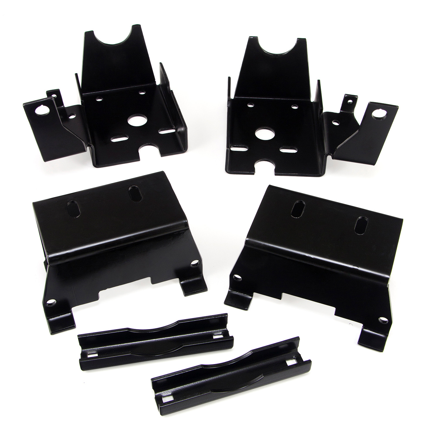
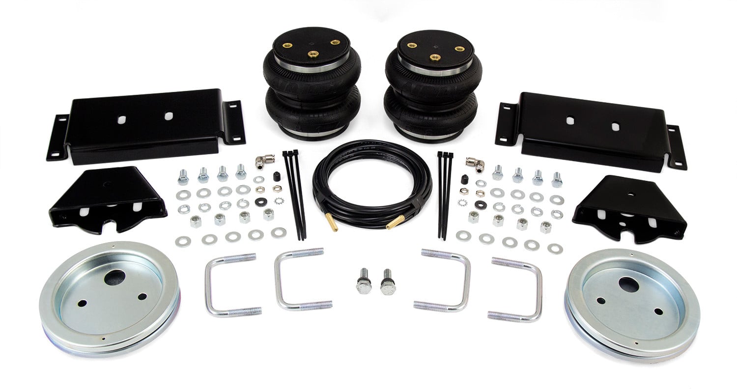
The kit includes: 2 lower brackets (part 03912), 1 left upper bracket (07802), 1 right upper bracket (07903), 2 axle clamp bars (01531), 2 air springs (58437), 4 roll plates (11951), 8 hex-cap screws 3/8"-24 x 7/8" (17203), 8 lock washers 3/8" (18444), 26 flat washers 3/8" (18444), 2 swivel elbow fittings 90-degree (21837), 2 P-clamps (10976), 2 round U-bolts (11520), 2 square U-bolts (11717), 4 carriage bolts 3/8"-16 x 4" (17166), 2 hex-head screws 1/4"-20 x 3/4" (17261), 2 J-bolts 3/8"-16 x 3.75" (17309), 2 hex flange bolts M14-1.5 x 40 (17508), 4 flat washers #12 (18419), 2 nylon lock nuts 1/4"-20 (18425), 18 nylon lock nuts 3/8"-16 (18435), 1 EVAP control valve bracket (11543), 1 hose assembly (20086), 6 zip ties (10466), 2 flat washers 5/16" (18501), 2 star washers (18411), 2 valve caps (21230), 4 hex nuts 5/16" (21233), and 2 rubber washers (21234).
The manual does not specify whether the battery must be disconnected. Contact Air Lift customer service at (800) 248-0892 for clarification on this safety requirement.
The first step is to raise the vehicle and support it using safety stands or equivalent so the axle can be safely dropped away from the frame. This is necessary to position the air spring assembly between the axle and frame. The manual shows the vehicle on a drive-on hoist with the axle supported.
Yes. You must pull the plastic harness fasteners away from the frame on the wiring harness behind the axle on both the passenger's (right) and driver's (left) side so that the harness is loose from the frame. This is done early in the installation process to provide clearance.
Yes. You must unbolt and pull aside the frame vent tube bracket and the vent tube itself so that it is away from the frame. This is done early in the installation and the vent tube will be reattached later.
Yes. You must remove the rear 5th-wheel hitch frame bolts and discard them. This is necessary to provide clearance for the upper bracket installation.
Yes. You must remove the ABS lines from the brackets on both the driver's (left) and passenger's (right) side axle. These lines will be reattached later using P-clamps and zip ties.
Yes, on the driver's (left) side only. You must loosen the left bolt that holds the rear brake line to the rear axle bracket, then rotate the brake line counter-clockwise as far as it will go. Tighten the brake line bolt so the line stays in this position. This is done to gain clearance for the lower bracket.
Yes, on gas models only. You must pull up on the EVAP control valve to remove it from the frame bracket, then bend the "fingers" on the bracket inboard and down using channel lock pliers or equivalent. Let the EVAP control valve hang at this time. The bracket will be reattached later during the installation.
Insert the J-bolts (part 17309, 3/8"-16 x 3.75") into the large hole on the inside of the frame rail, just behind the round crossmember, on both the driver's (left) and passenger's (right) sides. These bolts will later align with holes in the upper brackets.
Insert the square U-bolt (part 11717, L) around the spring perch, forward of the axle. Then rotate it around the back side of the perch, making sure that the U-bolt fits in between the ABS line/bracket and the spring. This U-bolt will later attach the lower bracket to the axle.
Set the round U-bolts (part 11520, K) into position over the round crossmember located above the axle on both the driver's (left) and passenger's (right) side. Be careful not to pinch any wiring that may be in the area on the driver's (left) side.
1. Set roll plates (part 11951, E) on top of the air springs (part 58437, D) with the radiused edge toward the air springs. 2. Install the 90-degree swivel fittings (part 21837, I) into the top of the air springs, finger-tight plus one and a half turns. 3. Set both upper brackets (parts 07802 and 07903, B1 and B2) onto the top of the air springs and attach with two 3/8"-24 x 7/8" hex-cap screws (part 17203, F), 3/8" lock washers (part 18444, G), and 3/8" flat washers (part 18444, H). Leave loose at this time.
Flip the assemblies upside down and set roll plates on the bottom of the air springs. Install the lower brackets (part 03912, A) onto the air spring assemblies with two 3/8"-24 x 7/8" hex-cap screws (part 17203, F), 3/8" lock washers (part 18444, G), and 3/8" flat washers (part 18444, H). Make sure that the flanges on the lower brackets face the fittings on the top of the air springs. Leave loose at this time.
The air fittings on the assemblies must face the outboard (tire side) of the vehicle when the assemblies are positioned onto the axle.
Raise the axle up just enough that the upper bracket touches the frame. While raising the axle, align the J-bolt and round U-bolts with the holes in the bracket. Attach the upper bracket to the 5th-wheel mounting hole located on the side of the frame using the M14-1.5 x 40 hex flange bolt (part 17508, P). Apply medium-strength (blue) threadlocker compound to the bolt before inserting it into the hole.
Torque the 3/8" U-bolts and J-bolts evenly to 15 lb.-ft. (20 Nm). Snug the M14 bolt first, then torque the U-bolts and J-bolts evenly, then torque the M14 hardware to 77 lb.-ft. (105 Nm).
Torque the M14-1.5 x 40 hex flange bolt (part 17508, P) to 77 lb.-ft. (105 Nm). Apply blue threadlocker compound to the bolt before installation.
The lower and upper mounting hardware should be tightened to no more than 20 lb.-ft. (27 Nm). This applies to both the lower bracket mounting hardware and the upper bracket alignment hardware.
Torque the axle clamp hardware to 15 lb.-ft. (20 Nm). Tighten the axle spring clamp evenly until tight before applying the final torque.
Torque the spring perch/lower bracket hardware to 15 lb.-ft. (20 Nm). Snug the hardware evenly first (do not tighten at this time), then apply the final torque.
Insert two 3/8"-16 x 4" carriage bolts (part 17166, M) through the holes in the lower bracket and install the lower axle clamp bar (part 01531, C) under the axle. Cap the carriage bolts with two 3/8" flat washers (part 18444, H) and 3/8"-16 nylon lock nuts (part 18435, S). Do not tighten at this time. Later, tighten the axle spring clamp evenly until tight, then torque to 15 lb.-ft. (20 Nm).
Push the lower bracket up against the stock leaf spring U-bolts, making sure the tabs on the lower bracket are locked around the outside of the U-bolts. Snug the spring perch/lower bracket U-bolt evenly (do not tighten at this time). The tabs must engage the outside of the U-bolts to properly secure the assembly.
In final adjustments, push the air spring inboard on the lower bracket and tighten the lower hardware to no more than 20 lb.-ft. (27 Nm). Then align the air spring by moving it forward or backward on the upper bracket, and tighten the upper mounting hardware to no more than 20 lb.-ft. (27 Nm).
Install the P-clamp (part 10976, J) over the wiring on the driver's (left) side and attach to the upper bracket, with the "P" facing the frame. Attach the P-clamp with one 1/4"-20 x 3/4" hex-head screw (part 17261, N), two #12 flat washers (part 18419, Q), and one 1/4" nylon lock nut (part 18425, R). Tighten securely.
On gas models only: 1. Install the P-clamp (part 10976, J) around the wiring harness on the driver's (left) side. 2. Insert one 1/4"-20 x 3/4" bolt (part 17261, N) into the EVAP control valve bracket (part 11543, T). 3. Insert the bracket into the EVAP control valve using the same slot the stock bracket was removed from. 4. Install the assembly onto the upper bracket. 5. Install the P-clamp previously put around the wiring onto the EVAP control valve mounting bolt and attach with a #12 flat washer (part 18419, Q) and 1/4" nylon lock nut (part 18425, R). If necessary, rotate or bend the bracket to gain as much clearance around the control valve as possible. Tighten securely.
Install the P-clamp (part 10976, J) around the passenger's (right) side wiring and ABS line that had been previously removed. Along with the previously removed axle vent tube bracket, attach the P-clamp and wiring to the upper bracket using the same hardware specified from the driver's (left) side: one 1/4"-20 x 3/4" hex-head screw (part 17261, N), two #12 flat washers (part 18419, Q), and one 1/4" nylon lock nut (part 18425, R). Tighten securely.
Yes. Bend the emergency brake line brackets located on the axle forward on both the driver's (left) and passenger's (right) side, forward of the axle, far enough for the line to gain clearance of the lower bracket.
Tie off the ABS line on the passenger's (right) side, which was disconnected from the axle bracket, to the axle vent tube with a zip tie (part 10466, U). Tie off the ABS line behind the axle on the driver's (left) side to the soft brake line with a zip tie (part 10466, U).
Yes, you must choose the location for the Schrader valve and drill a 5/16" (8 mm) hole if necessary. The manual shows three optional locations: inside the fuel tank filler door, inside the rear wheel wells, or in the license plate or rear bumper area. Make clean, square cuts with a razor blade or hose cutter when cutting the air line.
Yes, you must drill a 5/16" (8 mm) hole for the Schrader valve. The manual provides three optional locations: inside the fuel tank filler door, inside the rear wheel wells, or in the license plate or rear bumper area.
Cut the air line in half using a hose cutter, razor blade, or sharp knife. Make clean, square cuts. Do not use scissors or wire cutters, as these will damage the air line.
Use zip ties to secure the air line to fixed points along the chassis. Do not pinch or kink the air line. Leave at least 2" of slack in the air line to allow for any movement that might pull on the air line. The minimum bend radius for the air line is 1" (25 mm). Keep at least 6" (152 mm) of clearance between all air lines and the exhaust system. Avoid sharp bends and edges.
Keep at least 6" (152 mm) of clearance between all air lines and the exhaust system. If a heat shield was included in the kit, install it. If there is no heat shield but one is required, call Air Lift customer service at (800) 248-0892.
Attach the metal heat shield to the exhaust where it is closest to the air spring. Slide the air line thermal sleeve over the air line and place it where the air line is closest to the exhaust. Maintain 1/2" (13 mm) dead air space between the shield and exhaust. Use double hose clamps if necessary.
The minimum bend radius for the air line is 1" (25 mm). Avoid sharp bends and edges when routing the air lines.
The maximum air pressure is 100 PSI (7 BAR). Although the air springs are rated at this maximum inflation pressure, the air pressure actually needed is dependent on load and gross vehicle weight rating. Never inflate beyond 100 PSI (7 BAR).
The minimum recommended pressure is 5 PSI (0.34 BAR). Always maintain normal ride height and check air pressure weekly.
No. For safety and to prevent possible damage to the vehicle, do not exceed the maximum gross vehicle weight rating (GVWR) or payload rating as indicated by the vehicle manufacturer. The LoadLifter 5000 is designed to level the vehicle under load, not to exceed its rated capacity.
Perform the following checks in order: 1. Clearance test — Inflate the air springs to 40-60 PSI (2.8-4.1 BAR) and ensure at least 1/2" (13 mm) clearance from anything that might rub against each sleeve. Check the tire, brakes, frame, shock absorbers, and brake cables. 2. Leak test — Inflate the air springs to 40-60 PSI (2.8-4.1 BAR) and check all connections for leaks. All leaks must be eliminated before road testing. 3. Heat test — Ensure sufficient clearance from heat sources, at least 6" (152 mm) for air springs and air lines. 4. Fastener test — Recheck all bolts for proper torque. 5. Road test — Drive the vehicle 10 miles (16 km) and recheck for clearance, loose fasteners, and air leaks.
Inflate the air springs to 40-60 PSI (2.8-4.1 BAR) for both the clearance test and leak test. Check all connections for leaks and ensure at least 1/2" (13 mm) clearance from anything that might rub against each sleeve.
Inflate the air springs to 40-60 PSI (2.8-4.1 BAR) and make sure there is at least 1/2" (13 mm) clearance from anything that might rub against each sleeve. Be sure to check the tire, brakes, frame, shock absorbers, and brake cables.
Use a soapy water solution to check all air line connections and the inflation valve core. All leaks must be eliminated before the vehicle is road tested. Do not deflate and remove the air spring until the source of the leak has been identified.
Drive the vehicle 10 miles (16 km) and recheck for clearance, loose fasteners, and air leaks. This ensures that all components have settled into their final positions and that no issues have developed during initial operation.
Check air pressure weekly. Regular pressure checks help ensure the system is functioning properly and that the vehicle maintains the desired ride height.
Check air pressure weekly. Always maintain normal ride height. Never inflate beyond 100 PSI (7 BAR). If the system develops an air leak, use a soapy water solution to check all air line connections and the inflation valve core before deflating and removing the air spring.
Use a soapy water solution to check all air line connections and the inflation valve core. Spray the solution on all connections and look for bubbles, which indicate a leak. All leaks must be eliminated before the vehicle is road tested.
On Sale Today
Original price was $667.99. Current price is $483.99.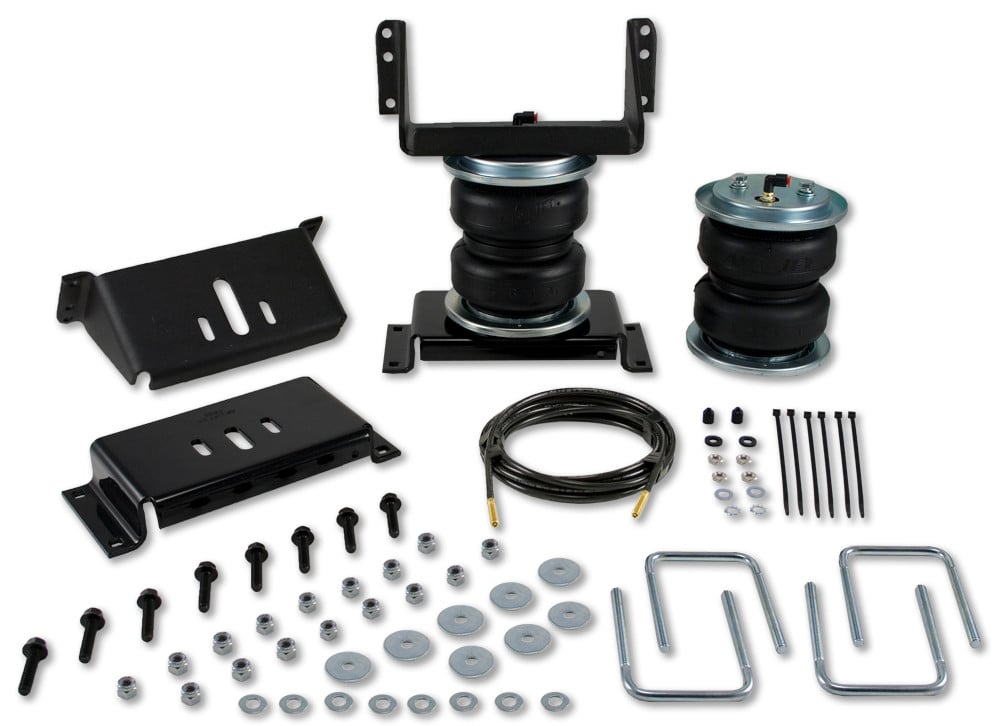

You save $184.00 (28%)
Free Shipping
Ships free on all orders
 Authorized Dealer
Quick Ship
In stock and ready to ship — order now!
FREE ShippingFREE SHIPPING
Estimated delivery Thu, Sep 24 - Sun, Sep 27
Order before 2 PM EST Monday–Friday for same-day processing
Guaranteed safe & secure checkout
No reviews have been added for this product.