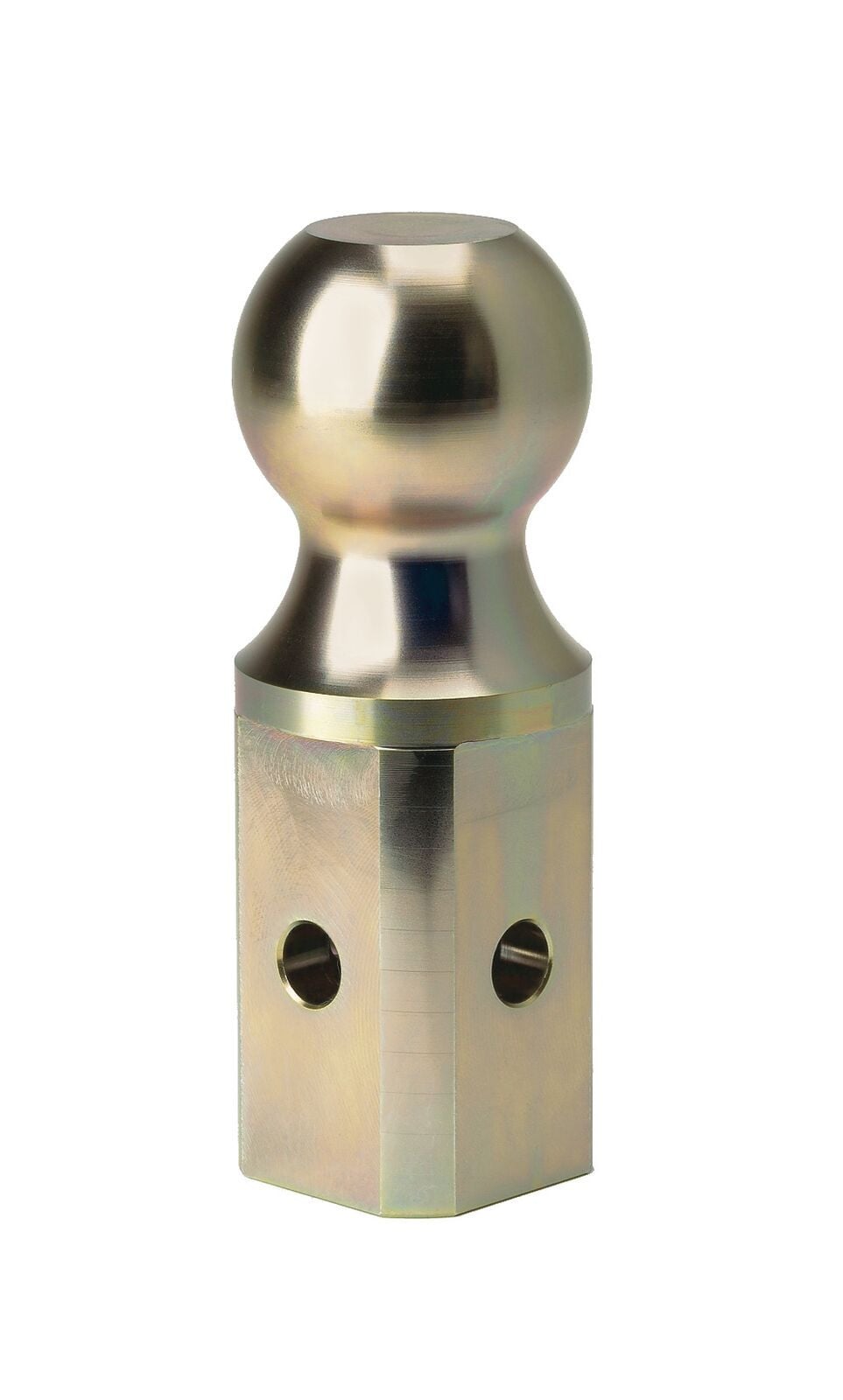
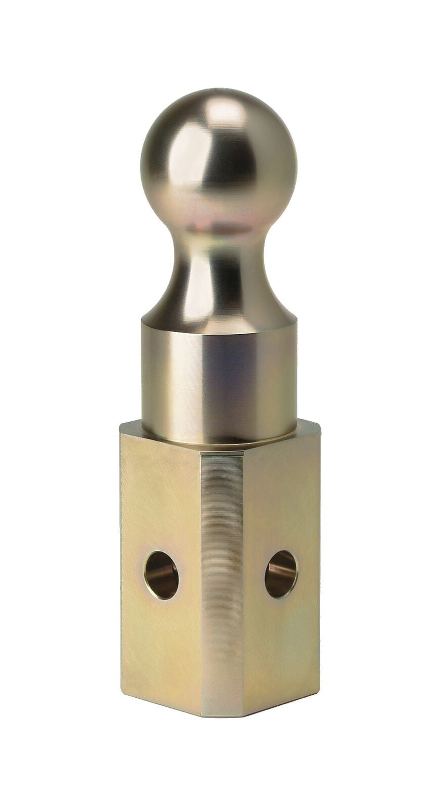
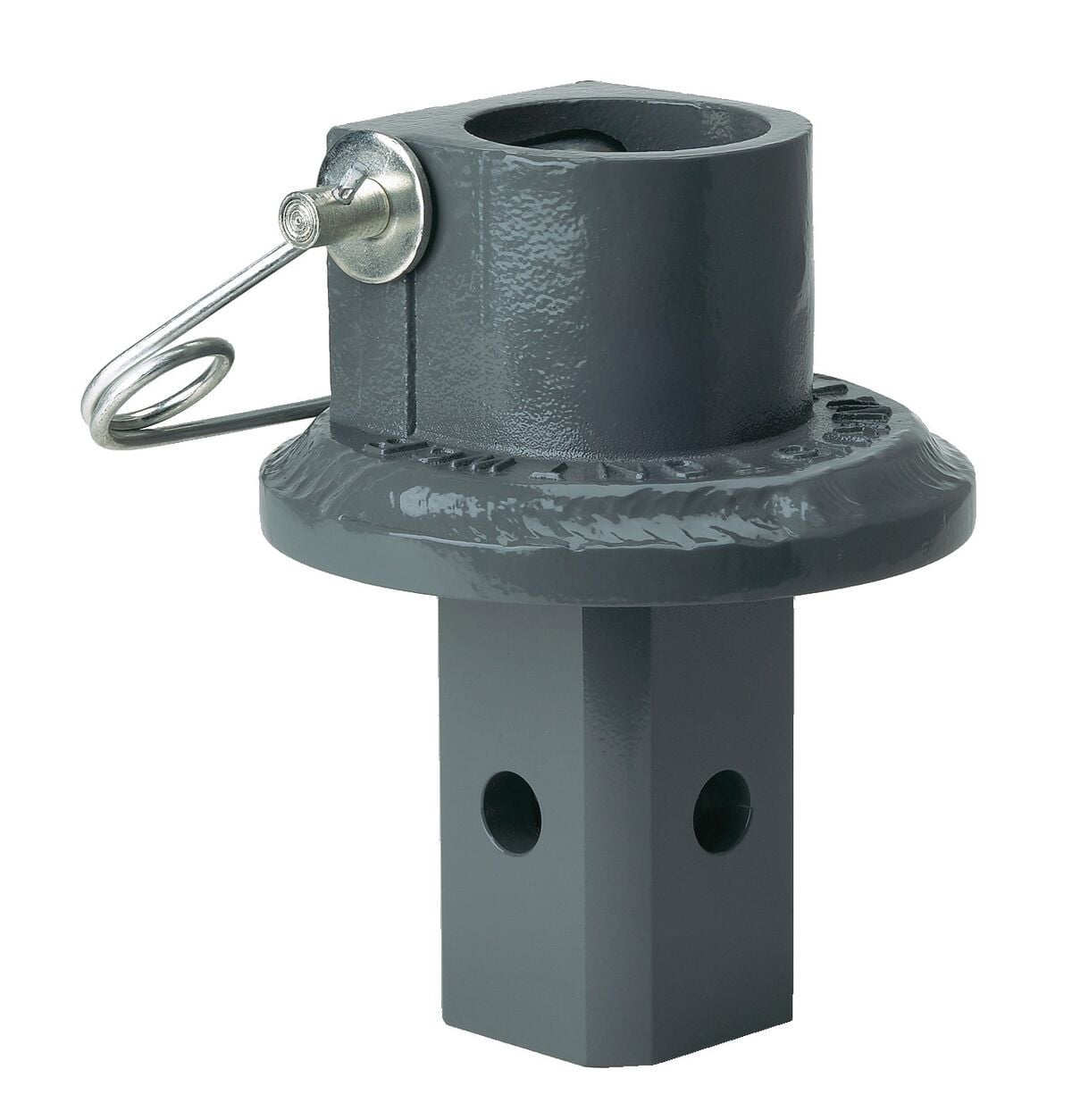
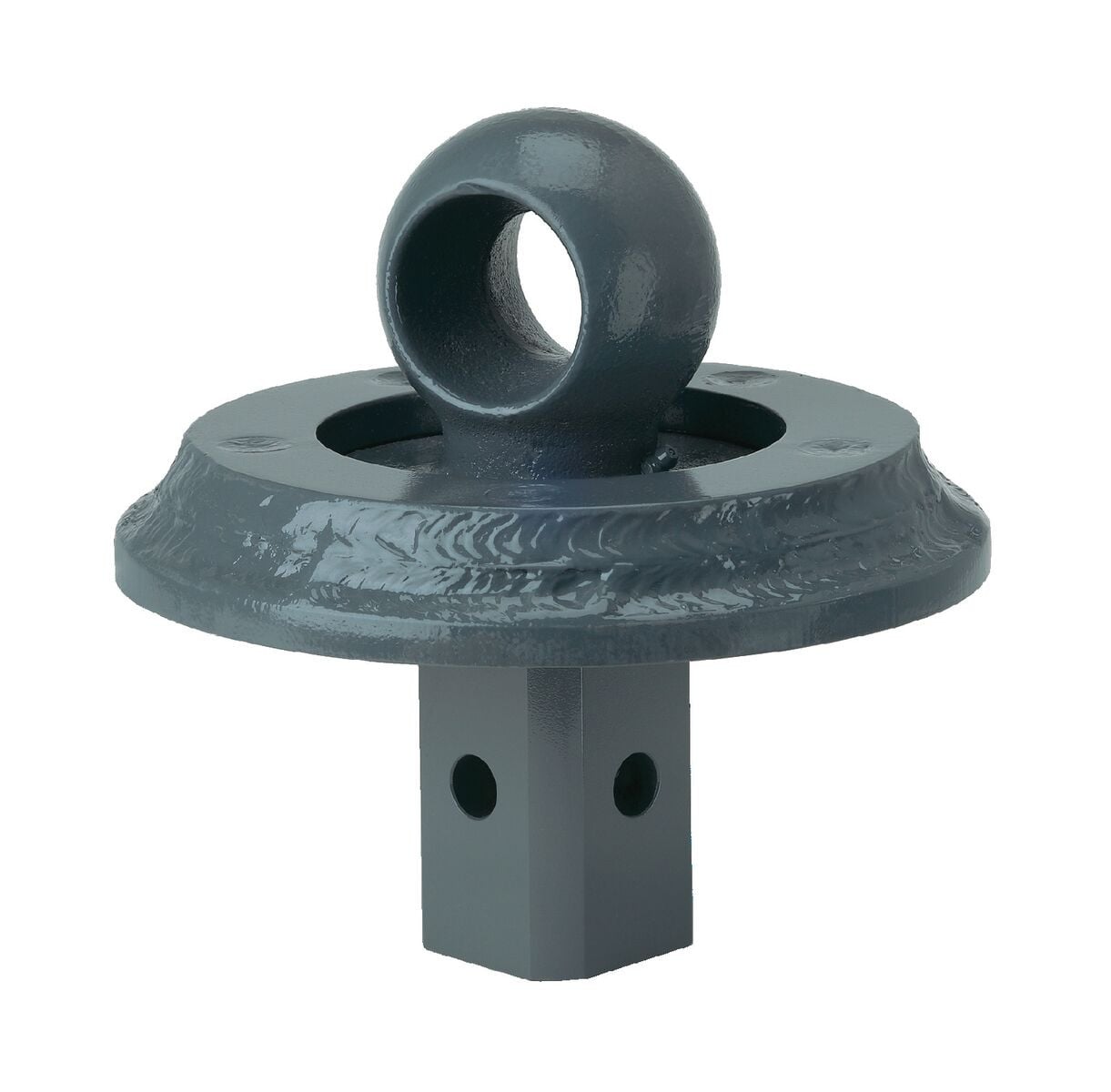
B&W Trailer Hitches 2-5/16" Replacement Ball For Turnoverball Gooseneck Trailer Hitch Ball GNXA2000B&W Trailer Hitches$86.00In Stock
View productOur in-house experts typically reply within one business day.

B&W Trailer Hitches
Verify Fitment
Select your vehicle to confirm this part fits.
2022 - 2025 Toyota Tundra
Confirmed to Fit


Always the correct part
We know our products
Quality Products
Free Shipping!
Always the correct part
We know our products
Quality Products
Free Shipping!
Free Shipping
Ships free on all orders
 Authorized Dealer

Quick Ship
In stock and ready to ship — order now!
FREE ShippingFREE SHIPPING
Estimated delivery Sun, Aug 30 - Wed, Sep 2
Order before 2 PM EST Monday–Friday for same-day processing
Guaranteed safe & secure checkout
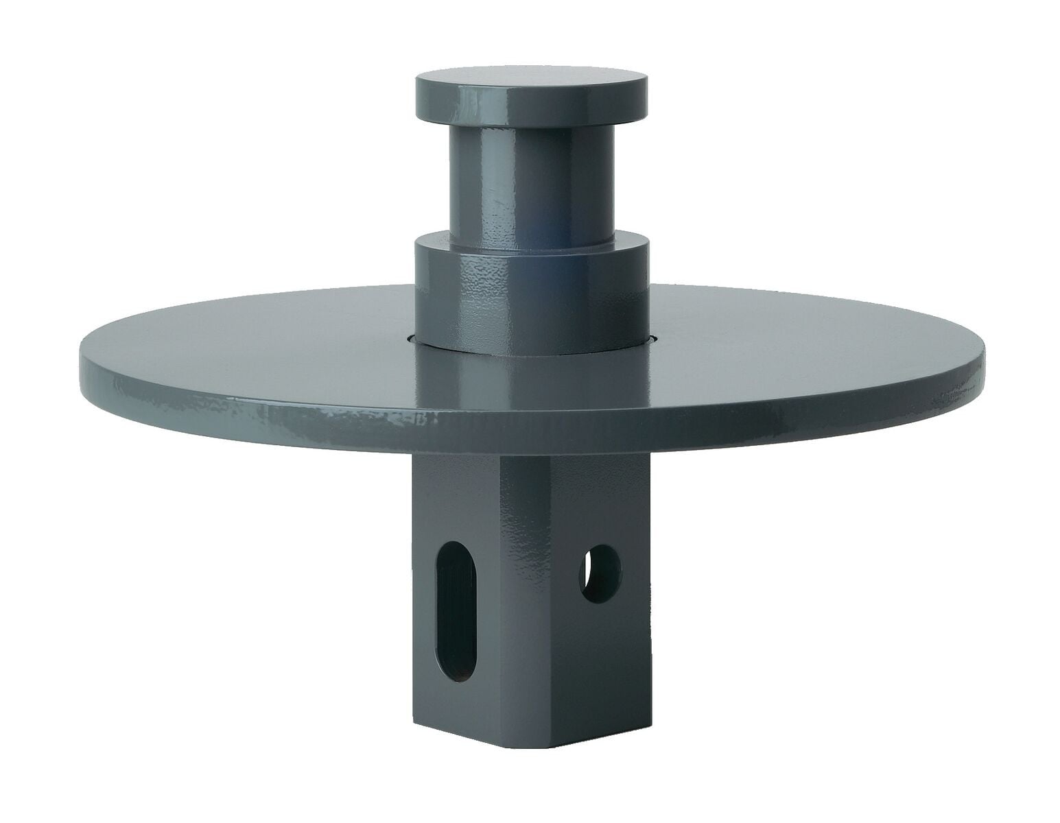
Effortlessly set up your B&W Turnoverball gooseneck trailer hitch center section (BW36FR - not included) with our custom-designed installation kit.
Upgrade your towing experience with our B&W Turnoverball Gooseneck Installation Kit. It's not just a product, it's a promise of quality and convenience.

B&W Trailer Hitches is an American manufacturer known for durable, innovative towing products, including gooseneck hitches, fifth-wheel hitches, receiver hitches, and ball mounts. Built in Kansas by employee-owners, B&W products are engineered for dependable performance, easy installation, and long-lasting quality.
B&W Trailer Hitches is an American manufacturer known for building innovative, dependable towing products designed to make hitching easier and towing more comfortable. The company began in 1987 in Humboldt, Kansas, when founders Roger Baker and Joe Works combined their fabrication experience to build custom truck beds and solve common problems faced by truck owners.
B&W changed the gooseneck hitch industry with the introduction of the Turnoverball Gooseneck Hitch. Its under-bed mounting system and reversible hitch ball allowed truck owners to quickly store the ball beneath the bed, leaving a clean and unobstructed surface when the hitch was not in use. B&W later applied the same practical approach to the Companion Fifth Wheel Hitch, creating a removable fifth-wheel hitch engineered for a quiet, smooth, and secure towing experience.
Today, B&W manufactures gooseneck hitches, fifth-wheel hitches, receiver hitches, ball mounts, and towing accessories at its nearly 600,000-square-foot facility. The company is owned by approximately 500 employee-owners who remain committed to American manufacturing, trusted materials, skilled craftsmanship, and long-lasting product quality.
Whether you are towing a work trailer, livestock trailer, camper, or fifth wheel, B&W Trailer Hitches offers thoughtfully engineered towing equipment built to perform mile after mile.
Experts available to answer your questions
Call 888-634-94941 compatible vehicles
| Year | Make & Model | Notes |
|---|---|---|
| 2022 - 2025 | Toyota Tundra | — |
The 2022 Toyota Tundra Trucks B&W Turnoverball Mounting Kit GNRM1222 (Part #BQVLGNRM1222) fits 2022-2025 Toyota Tundra models. The 2025 model year is the last year covered by this part number. For newer models, check for an updated version.
Yes, the 2022 Toyota Tundra Trucks B&W Turnoverball Mounting Kit GNRM1222 (Part #BQVLGNRM1222) is designed to fit the 2022-2025 Toyota Tundra.
The 2022 Toyota Tundra Trucks B&W Turnoverball Mounting Kit GNRM1222 (Part #BQVLGNRM1222) fits the following vehicles: 2022-2025 Toyota Tundra. Always verify your specific year, make, and model before ordering.
The 2022 Toyota Tundra Trucks B&W Turnoverball Mounting Kit GNRM1222 (Part #BQVLGNRM1222) Refer to the included instructions for installation details. Basic hand tools are typically all you need.
The Model 1222 is a gooseneck hitch designed specifically for 2022–2025 Toyota Tundra trucks. It comes equipped with a 2-5/16" ball and features a latch pin mechanism that can be inverted. The hitch mounts through the truck bed using a center section that passes through a 4" hole cut in the composite bed, with cross members and side plates securing it to the frame.
The Model 1222 is designed for 2022–2025 Toyota Tundra trucks in their original, unmodified condition. Compatibility with vehicles having replacement parts or other modifications is not guaranteed. You should inspect your vehicle for modifications before installation. The manual does not specify whether it fits crew cab, standard cab, or both configurations.
Yes. The 4" hole location is measured at 43-3/16" from the rear edge of the bed for both 8-foot long beds and short beds (less than 8 feet long). If your truck has a spray-in bed liner applied over the end of the bed, you must add the thickness of the liner to this measurement.
The Model 1222 comes equipped with a 2-5/16" ball. Trailers towed with this ball must have a 2-5/16" coupler. Towing with a larger coupler could cause loss of attachment between the trailer and the tow vehicle.
Required tools include: impact wrench or ratchet with 3/4" socket; 1/2", 3/4", and 12mm box end wrenches; marking tool (pencil or permanent marker); 4" hole saw; drill with 1/2" bit; pry bar; tape measure; torque wrench; pilot hole bit; flashlight; and ear protection. You will also need gloves, arm protection, eye protection, and nose and mouth protection rated for composite material work.
Yes. The spare tire must be removed before installation. Follow your vehicle manufacturer's instructions for removal. The tire is reinstalled after the hitch installation is complete.
Yes. The exhaust must be lowered to provide clearance for the center section. Locate the three rubber hangers toward the rear of the truck and use a pry bar to disconnect them from the exhaust. The exhaust is repositioned during installation and re-attached at the end.
Yes. A 4" hole must be cut through the composite truck bed using a 4" hole saw. Additionally, four 1/2" holes must be drilled through the bed for the safety chain U-bolts. The manual specifies that either a conventional hole saw or an abrasive-coated hole saw can be used for the composite material. All cut edges must be sealed with epoxy.
The 4" hole may be cut through both the removable bed liner and the bed. However, the manual warns that locating the center of the truck bed may be more difficult if the liner slides or moves, and failure to cut the hole in the correct location may adversely affect the installation and result in property damage. If you have a spray-in bed liner applied over the end of the bed, you must add the thickness of the liner to the 43-3/16" measurement.
At least two people are required to complete the installation. The manual specifically notes that positioning the center section under the bed is difficult and requires at least two people, and that some installation steps will need two people to complete.
A lifting device is recommended to safely hold the hitch in position during installation. The manual states that a simple mechanical lifting device is available for purchase from B&W. The device is used to pull the raised portion of the center section up through the 4" hole in the bed.
Yes. The truck must be lifted up by the frame so the suspension is relaxed. Installation occurs under the bed directly above the axle, and hitch components cannot be installed without adequate space between the axle and the bed. You must use only equipment designed for lifting and positioning vehicles for service.
Using a tape measure hooked over the rear edge of the bed at the tailgate end, measure 43-3/16" toward the front of the bed. Next, locate the center of the bed by measuring the distance between the wheel wells and dividing by two. The center of the 4" hole will be at the intersection of these two measurements. If your truck has a spray-in bed liner applied over the end of the bed, add the thickness of the liner to the 43-3/16" measurement.
Either a conventional hole saw or an abrasive-coated hole saw can be used to cut the 4" hole in the composite truck bed. After cutting, sand the edge of the hole to remove any burrs or frayed edges, and use a vacuum to remove composite dust.
Yes. Due to the composite construction of the bed, the edges of both the 4" hole and the four 1/2" drilled holes must be sealed with epoxy to restore the sealed surface finish and cover exposed fibers. The manual provides two epoxy packets for this purpose. Each packet should be mixed and applied within 3 minutes of opening. The 4" hole edge must dry at least 15 minutes before installing the center section, and the 1/2" holes must dry at least 15 minutes before installing the U-bolts.
The main torque specifications are: eight 1/2" bolts holding the center section to the cross members—110 ft. lbs.; four 1/2" carriage bolts holding the cross member brace to the cross members—110 ft. lbs.; four 1/2" bolts holding the side plates to the cross members—110 ft. lbs.; four 1/2" bolts holding the side plates to the frame—110 ft. lbs.; and the 5/16" nuts securing the latch pin handle—30 ft. lbs. The U-bolt lock nuts should be tightened until flush with the end of the U-bolt.
The 5/16" locking flange nuts securing the latch pin handle to the latching mechanism should be torqued to 30 ft. lbs.
The 1/2" lock nuts on the safety chain U-bolts should be tightened until the nut is flush with the end of the U-bolt. The manual does not provide a specific foot-pound torque value for these nuts.
The tightening sequence is critical and must be followed in this order: (1) Tighten the eight 1/2" bolts holding the center section to the cross members to 110 ft. lbs.; (2) Tighten the four 1/2" carriage bolts holding the cross member brace to the cross members to 110 ft. lbs.; (3) While ensuring the side plates are tight against the frame, tighten the four 1/2" bolts holding the side plates to the cross members to 110 ft. lbs.; (4) Finally, tighten the four 1/2" bolts holding the side plates to the frame to 110 ft. lbs. Failure to follow this sequence may result in hitch misalignment, which could affect performance or result in property damage or serious injury.
Most bolts should be left snug but not fully tightened until the final tightening sequence. The manual specifically states "Do not fully tighten hardware at this time" for the center section attachment (Step 4), cross member brace attachment (Step 7), side plate attachment to cross members (Step 1 of Install Side Plates), and side plate attachment to frame (Step 1 of Install Side Plates). Only after the center section is properly positioned and spaced should you follow the final tightening sequence to 110 ft. lbs.
Before installation, you must: (1) Remove the spare tire; (2) Lower the exhaust by disconnecting three rubber hangers; (3) Detach the fuel pump control module from the passenger side wheel well; (4) Detach tubing brackets and disconnect plastic tubing in front of the first bracket; (5) Detach the vent tube from the large canister near the rear; (6) Remove four plastic slot covers from the rear wheel wells; (7) Detach any wire/line connected to the top of the differential and the bed cross member above it, if present.
With the latch pin side of the center going forward and the raised portion up, guide the center over the exhaust. Move the center section to the driver side so the edge near the passenger side passes the two disconnected tubes. Pull down on the exhaust and move it toward the passenger side. Pull down and rotate the two tubes to make room for the center. Move the center forward and toward the passenger side so it passes over the two tubes. Once the tubes are under the cutouts in each flange of the center section, move the center back toward the rear of the truck and let it rest on the exhaust and tubes. A second person should carefully pull down on the tubes to give clearance.
Fish wire is used to thread carriage bolts and locking straps through the frame mounting slots. The fish wire is passed from the forward mounting slot through the frame and out of the rear mounting slot, carrying the carriage bolt and locking strap with it. This allows the bolts to be positioned inside the frame without direct access.
Pass the handle under the bed between the cross members on the driver side wheel well with the bend in the handle facing up. From the top down, insert a 5/16" carriage bolt in each of the square holes in the latching mechanism. Attach the handle to the latching mechanism over the 5/16" carriage bolts with two 5/16" locking flange nuts. The handle must not interfere with any other vehicle components; you may need to adjust the handle position by loosening the nuts and repositioning it. Finally, torque the nuts to 30 ft. lbs.
First, drill four 1/2" holes through the bed using the four guide holes as reference, pulling the exhaust toward the passenger side if needed. Remove any burrs created during drilling. Seal the edges of the drilled holes with epoxy and allow at least 15 minutes drying time. From the top side of the truck bed, drop a U-bolt in each set of holes. Place a conical spring over each leg of the U-bolts and secure with a 1/2" lock nut, tightening until the nut is flush with the end of the U-bolt.
After installation, you must: (1) Check latch pin engagement by pushing the handle toward the rear until the pin engages, verifying the pin passes completely through both walls of the ball socket, and making a mark on the latching mechanism to verify correct positioning; (2) Re-attach the exhaust hangers, tubing brackets, vent tube, and any detached wire to the differential; (3) Replace the spare tire; (4) Lubricate the 2-5/16" ball by applying a light coating of grease to the corners of the square shank; (5) Engage the pin by moving the handle toward the rear until it retracts and engages the ball.
With the ball removed, push the handle toward the rear of the truck until the handle retracts and the latch pin engages. Visually inspect the ball socket and verify that the latch pin has passed completely through both walls of the socket. Make a mark on the latching mechanism at the location shown in Figure G1 to indicate where the latching mechanism should be when the pin is correctly positioned. Retract the pin, replace the ball, and re-engage the pin. Check the marked location on the latching mechanism. If the mark is in the same location as when originally made, the latch pin has gone completely through the ball socket.
A visual inspection of the hitch should be performed before each time you tow. Regularly check that all pinned connections are secure and that all bolted connections are at the correct torque specification (110 ft. lbs. for main bolts, 30 ft. lbs. for handle nuts). Check for cracks or damage to the hitch. Do not tow with the hitch if cracks or damage outside of normal wear is found. Lubricate the 2-5/16" ball by applying a light coating of grease to the corners of the square shank.
The manual does not specify the tow capacity of the Model 1222. It states that you must not exceed the tow or tongue rating of the coupler, the tow or tongue rating of the hitch, or the tow or weight ratings of the truck or trailer. You should consult the vehicle and trailer manufacturer information for these ratings.
No. Operating the tow vehicle while the latch is in the open position may allow the handle to come into contact with the rear tire, which may damage the tire or the handle and could lead to serious injury or death. The latch should only be put in the open position when inverting the 2-5/16" ball or installing a B&W towing accessory.
No. Inverting the ball while hauling heavy loads may cause the ball to strike the truck's differential, drive line, or other components. You must inspect the relationship between the ball and truck components to ensure proper clearance. Failure to remove the ball when hauling heavy loads may result in property damage, injury, or death. A cover to prevent debris from entering the socket while operating without the ball in place is available from B&W.
Additional caution must be used when towing a wedge car trailer. Towing stability greatly depends on keeping the center of gravity as low as possible. Load heavy cars over the axles. Never tow with a single car on the front of the trailer. When towing a wedge car trailer, never exceed speeds that are reasonable for the roadway conditions (such as turns or curves). Failure to account for proper trailer center of gravity and reasonable speeds may cause damage to the truck, trailer, towing components, and loss of attachment between the truck and trailer.
You must wear gloves, arm protection, eye protection, and nose and mouth protection, all rated for use with composite material. This is required when cutting the 4" hole, drilling the 1/2" holes, and sealing the edges with epoxy. The epoxy manufacturer's material safety data sheet (MSDS) should be reviewed to select proper protective equipment; it can be found at https://theepoxysource.com/epoxy.htm under "RED EXTRA FAST" & "Reorder #04001".
The epoxy packets have a 24-month shelf life. If the date code on the center box is older than 24 months, call B&W for a replacement epoxy kit.
Failure of the pin to engage the ball and hitch properly could result in a loss of attachment between the trailer and the tow vehicle. If you experience engagement issues, verify that the handle is installed correctly by checking that it does not interfere with any other vehicle components. If problems persist, contact B&W at hitches@turnoverball.com or 800-248-6564 for support.
No. Do not modify this product in any manner. Doing so could alter its integrity and lead to a loss of attachment between the trailer and the tow vehicle.
If your truck has a removable bed liner, the 4" hole may be cut through both the liner and the bed. However, locating the center of the truck bed may be more difficult if the liner slides or moves. If your truck has a spray-in bed liner applied over the end of the bed, you must add the thickness of the applied liner to the 43-3/16" hole location measurement.
Due to the composite construction of the bed, if you intend to use a Companion 5th Wheel RV Hitch, installation of the plastic foot pads is not needed.
Yes, the Model 1222 is designed for 2022–2025 Toyota Tundra trucks in original, unmodified condition. Inspect your vehicle for modifications before installation, as compatibility is not guaranteed if parts have been replaced or other modifications made.
You need an impact wrench or ratchet with 3/4" socket, 1/2"/3/4"/12mm wrenches, a 4" hole saw, a 1/2" drill bit, a torque wrench, a pry bar, tape measure, marking tool, flashlight, and protective equipment (gloves, arm protection, eye protection, nose and mouth protection rated for composite material).
Main bolts (center section, cross member brace, side plates): 110 ft. lbs. Latch pin handle nuts: 30 ft. lbs. U-bolt lock nuts: tighten until flush with the end of the bolt.
Perform a visual inspection before each tow. Check that all pinned connections are secure and all bolted connections are at correct torque (110 ft. lbs. for main bolts, 30 ft. lbs. for handle nuts). Check for cracks or damage. Lubricate the 2-5/16" ball with a light coating of grease on the square shank corners.
The Model 1222 comes equipped with a 2-5/16" ball. Your trailer must have a 2-5/16" coupler. Towing with a larger coupler could cause loss of attachment between the trailer and truck.
Yes. The spare tire must be removed following your vehicle manufacturer's instructions. The exhaust must be lowered by disconnecting three rubber hangers using a pry bar. Both are reinstalled after installation.
First, verify that the latch pin handle is installed correctly and does not interfere with any other vehicle components. You may need to adjust the handle position by loosening the 5/16" nuts and repositioning it. Then, perform the latch pin engagement check: with the ball removed, push the handle toward the rear until the pin engages, and visually inspect the ball socket to verify the pin passes completely through both walls. If the pin still does not engage properly, contact B&W at hitches@turnoverball.com or 800-248-6564.
The center section may be difficult to move toward the passenger side over the two tubes. Have a second person carefully pull down on the two tubes to give clearance to the center section. Ensure the exhaust is pulled down and moved to the driver side, and that the two tubes are pulled down and rotated to make room for the center.
The fuel pump control module is located on the frame inside the passenger side wheel well. It is held in place by two screws on the outside of the frame. Remove these screws and allow the module to hang freely to give clearance for cross member installation.
The plastic tubing bracket is located on the top of the frame cross member directly behind and above the axle. Locate this bracket and detach it. Next, disconnect the tubing directly in front of the first tubing bracket from either one of the tubes. Refer to Figures A5 and A6 in the manual for bracket locations.
Locate the large canister near the rear of the truck, under the bed. The vent tube is in the middle of the canister. Detach it using a pair of pliers.
The manual states that the hitch is designed to install only at the described location and that failure to place the 4" hole precisely may result in added difficulty during installation or property damage. If the hole is not in the correct location, do not proceed with installation. Contact B&W at hitches@turnoverball.com or 800-248-6564 for guidance before drilling a new hole.
Once the epoxy packet is open, it should be mixed and applied within 3 minutes. If the epoxy has hardened, you cannot use it. If the epoxy packets have a date code older than 24 months, they may not work properly. Call B&W for a replacement epoxy kit. For future applications, work quickly after opening the packet and follow the mixing and application instructions in Step 4 of the Prepare to Install section.
Ensure you are using a calibrated torque wrench and tightening in the correct sequence: (1) eight 1/2" bolts holding the center section to the cross members to 110 ft. lbs.; (2) four 1/2" carriage bolts holding the cross member brace to the cross members to 110 ft. lbs.; (3) four 1/2" bolts holding the side plates to the cross members to 110 ft. lbs.; (4) four 1/2" bolts holding the side plates to the frame to 110 ft. lbs. If bolts still will not tighten properly, contact B&W for support.
No reviews have been added for this product.