
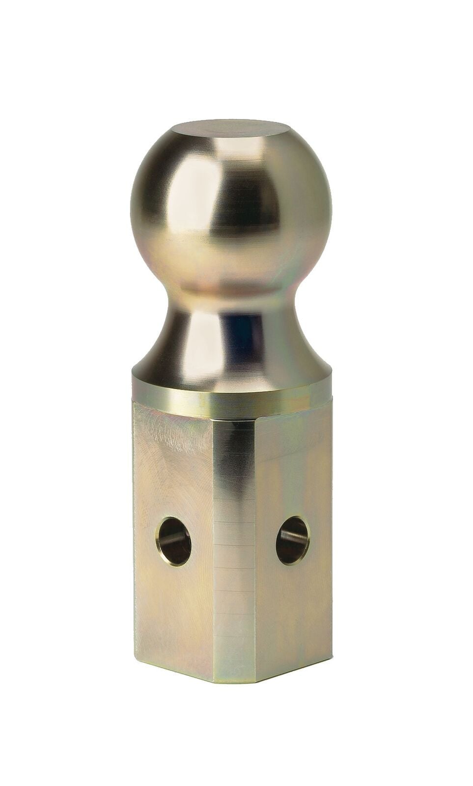
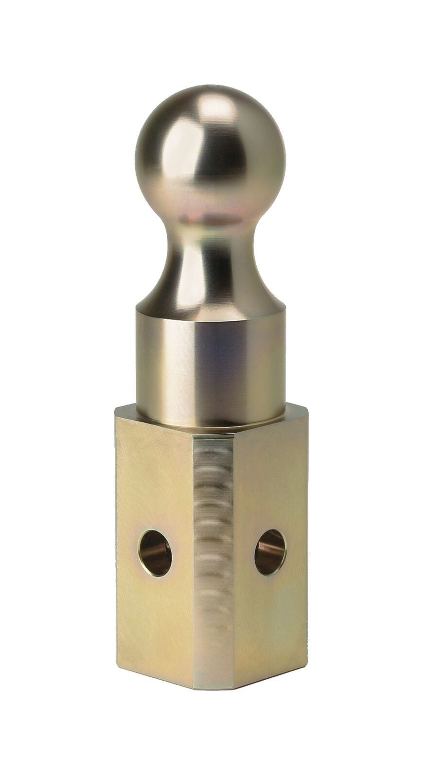
B&W Trailer Hitches 2-5/16" Replacement Ball For Turnoverball Gooseneck Trailer Hitch Ball GNXA2000B&W Trailer Hitches$86.00In Stock
View productOur in-house experts typically reply within one business day.

B&W Trailer Hitches


Always the correct part
We know our products
Quality Products
Free Shipping!
Always the correct part
We know our products
Quality Products
Free Shipping!
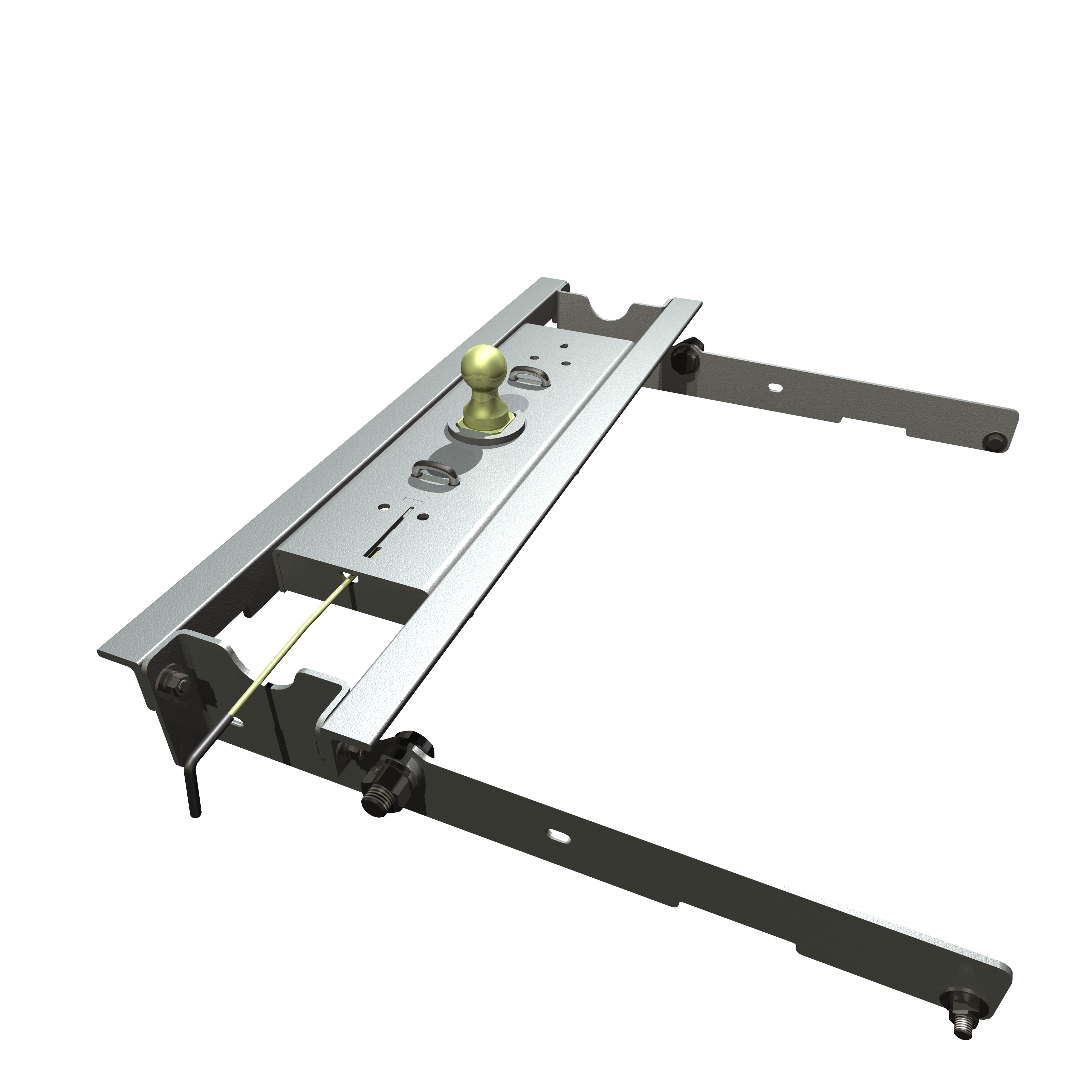
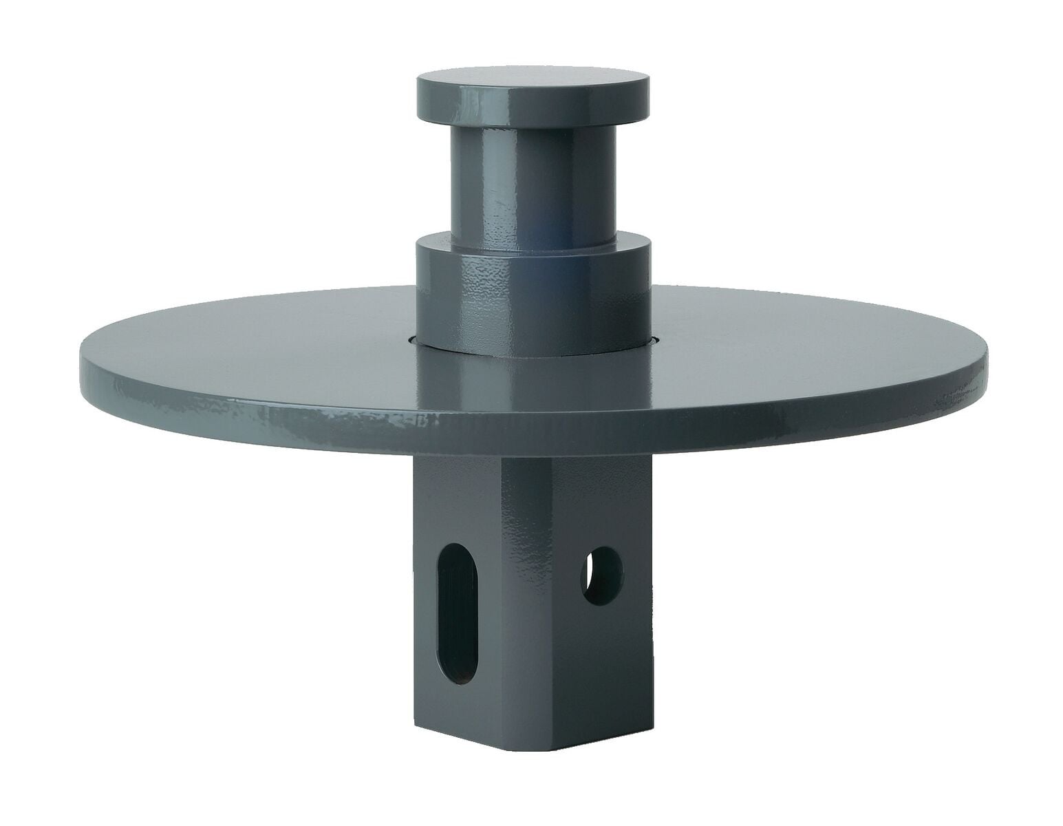
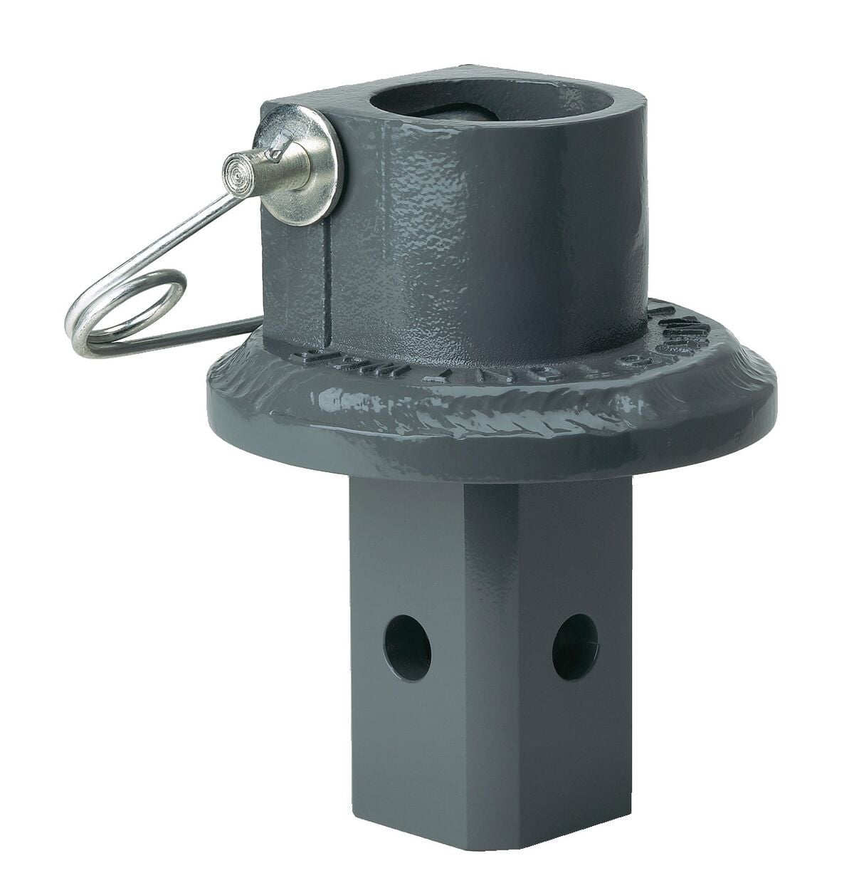
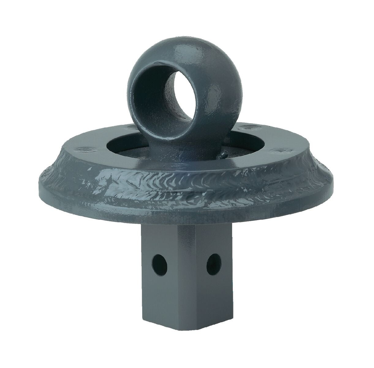
Equip your vehicle with this robust hitch to safely tow your gooseneck trailer. The removable ball can be stored upside down in the hitch when not in use, providing complete bed access. The square ball base is designed to stay put in the hitch.
The B&W Turnoverball under-bed gooseneck trailer hitch offers the best of both worlds. It provides a sturdy, reliable connection with your gooseneck trailer for towing, and when not in use, the ball can be stowed upside down in the hitch for full bed access and a clean look.
The durable steel hitch ball included with the Turnoverball system is secured in the hitch with a sturdy, 5/8" thick steel pin integrated into the end of the operating handle. To lock the ball in place, drop it into the hitch hole in your truck bed. Then rotate the handle in your driver's-side wheel well counterclockwise until the latch engages. When the latch is engaged, the spring-loaded pin on the end of the handle will be inserted all the way through the base of the hitch ball, forming a strong, solid connection for secure towing.
When you're done towing, remove the hitch ball by pulling the handle out as far as it will go and then rotating it clockwise until it unlatches. Flip the ball upside down and drop it back into the ball hole of the hitch. Then reengage the latch to secure the stowed ball in place.
The Turnoverball hitch ball is designed with a square base, unlike typical gooseneck balls with round bases. This design makes latching the ball in the hitch easier as the base won't rotate inside of the hitch, making pin alignment a breeze. The base of the ball also fits tightly within the ball hole during storage, preventing any dirt or grime buildup that could cause the ball to seize up in the hitch.
This hitch is custom designed for your vehicle. The included mounting brackets bolt to existing holes in your truck's frame. While some modification is required - you will need to cut a 4" diameter hole in your bed for the hitch ball and drill holes for the built-in safety chain loops - there is no need to weld onto or to drill into your frame.
Once you have the hitch brackets and body installed, set up the operating handle. This handle is designed to be accessed from the rear driver's-side wheel well. On the end of the handle is the heavy-duty steel pin that secures the hitch ball.
B&W makes it easy to tow just about anything. With the many adapters and accessories available, the Turnoverball can be made to work with almost any gooseneck trailer. Hitch balls are available that have a built-in rise, an offset, and even a different connection type. Add on the Companion fifth-wheel hitch - which attaches directly to the Turnoverball with no other parts required - and you can tow your fifth-wheel trailer.

B&W Trailer Hitches is an American manufacturer known for durable, innovative towing products, including gooseneck hitches, fifth-wheel hitches, receiver hitches, and ball mounts. Built in Kansas by employee-owners, B&W products are engineered for dependable performance, easy installation, and long-lasting quality.
B&W Trailer Hitches is an American manufacturer known for building innovative, dependable towing products designed to make hitching easier and towing more comfortable. The company began in 1987 in Humboldt, Kansas, when founders Roger Baker and Joe Works combined their fabrication experience to build custom truck beds and solve common problems faced by truck owners.
B&W changed the gooseneck hitch industry with the introduction of the Turnoverball Gooseneck Hitch. Its under-bed mounting system and reversible hitch ball allowed truck owners to quickly store the ball beneath the bed, leaving a clean and unobstructed surface when the hitch was not in use. B&W later applied the same practical approach to the Companion Fifth Wheel Hitch, creating a removable fifth-wheel hitch engineered for a quiet, smooth, and secure towing experience.
Today, B&W manufactures gooseneck hitches, fifth-wheel hitches, receiver hitches, ball mounts, and towing accessories at its nearly 600,000-square-foot facility. The company is owned by approximately 500 employee-owners who remain committed to American manufacturing, trusted materials, skilled craftsmanship, and long-lasting product quality.
Whether you are towing a work trailer, livestock trailer, camper, or fifth wheel, B&W Trailer Hitches offers thoughtfully engineered towing equipment built to perform mile after mile.
Experts available to answer your questions
Call 888-634-9494
Yes, the 1980-1998 Ford F250 & F350 Without Overload Springs - Excludes Light Duty F250 B&W Turnoverball Kit GNRK1100 (Part #BQVLGNRK1100) is designed to fit the Ford F-250.
The 1980-1998 Ford F250 & F350 Without Overload Springs - Excludes Light Duty F250 B&W Turnoverball Kit GNRK1100 (Part #BQVLGNRK1100) fits Ford F-250 models. The 1998 model year is the last year covered by this part number. For newer models, check for an updated version.
The 1980-1998 Ford F250 & F350 Without Overload Springs - Excludes Light Duty F250 B&W Turnoverball Kit GNRK1100 (Part #BQVLGNRK1100) fits the following vehicles: Ford F-250; 1997 Ford F-250 HD; 1980-1998 Ford F-350. Always verify your specific year, make, and model before ordering.
The 1980-1998 Ford F250 & F350 Without Overload Springs - Excludes Light Duty F250 B&W Turnoverball Kit GNRK1100 (Part #BQVLGNRK1100) Refer to the included instructions for installation details. Basic hand tools are typically all you need.
The hitch fits Ford 3/4 ton and 1 ton trucks from 1980–1998, and Ford 1/2 ton trucks from 1980–1996. For 1997–1998 trucks, the old body style is required. The hitch is designed for vehicles in original, unmodified condition. If your truck has replacement parts or modifications, compatibility is not guaranteed. Inspect your vehicle before installation. The hitch comes in three models: 1100R and 1150R (without overload springs) and 1110R (with overload springs).
Models 1100R and 1150R are designed for trucks without overload springs. Model 1110R is designed for trucks with overload springs. The installation procedure differs between these models, particularly in how the sideplates are fastened to the frame rails. If you have a truck with overload springs but own a 1100R or 1150R model, the sideplates can be modified by cutting 10 inches off the back (narrow end) and then installed following the 1110R procedure.
Before installing this hitch on a short-bed truck, you must check for adequate turning clearance between the front of all your trailers and the truck cab. The hitch may interfere with trailer turning radius on short beds. Perform this check before installation to ensure safe operation.
No. On 2-wheel-drive trucks, do not invert the ball in the socket when carrying heavy loads, as the ball may hit the top of the differential. Remove the ball from the socket before loading. A plug for the socket is available from B&W.
Required tools include: a saber saw with metal cutting blade or a 4" hole saw (for cutting the bed floor hole); a 7/32" hex head socket or wrench (for heat shield screws); a ratchet strap (for tail pipe repositioning on Power Stroke diesel); a crescent wrench or channel locks (for rotating the rear crossmember); a socket wrench set (for 1" and 1/2" bolts); a torque wrench (for final fastener tightening to 90 ft-lbs); and a drill with 1/2" bit (for safety chain bracket holes and, on 1110R models, for frame rail holes). An overhead lifting device such as a chain fall, engine hoist, or cable come-a-long is recommended for raising the center section into position.
An overhead lifting device such as a chain fall, engine hoist, or cable come-a-long is recommended but not strictly required. It is used to lift the center section into position by looping rope or chain through the 4" hole in the truck bed floor and attaching it to the latch pin in the round hitch receiver tube. The lifting device should be disconnected before squaring the center section across the frame, installing the sideplates, and torquing fasteners. If you do not use a lifting device, you will need to raise the center section manually from beneath the truck.
Most trucks have fuel lines, brake lines, and electrical wires located along the frame rails where this hitch installs. Before installation, carefully examine the location of these lines and wires. Ensure you will not damage them when positioning hitch components, drilling holes, tightening fasteners, and lifting or lowering the truck bed. Pay special attention to the fuel tank vent located on top of the gas tank, which can be easily damaged during installation of the front crossmember and center section. In Step Five, you must locate and release the brake line and fuel line retaining clip from the frame rail on the driver's side.
The manual does not specify whether battery disconnection is required. Contact B&W Trailer Hitches at 620.473.3664, 800.248.6564, or hitches@turnoverball.com for guidance on this step.
Mark a 4" round hole on the topside of the truck bed floor, centered between the wheel wells and 49" from the tailgate end of the bed. Drill a small hole inside the marked area and cut out the circle using a saber saw with a metal cutting blade or a 4" hole saw. The round hitch receiver tube that protrudes from the center section must fit through this hole.
Yes. You must drill four 1/2" holes through the truck bed floor for the safety chain brackets. Drill these holes from beneath the truck, through the four holes farthest from the round hitch receiver tube in the center section. Drop a U-bolt through each pair of holes from the topside of the truck bed floor, place a spring and lock nut on each of the four legs, and tighten the lock nuts until 1/4" of thread extends through the lock nut.
Yes. For model 1110R, it is necessary to drill a 1/2" hole in the frame rails through the slot nearest the front of the sideplate. Jacking up the back of the truck will raise the frame higher than the tire, making it easier to drill this hole. Fasten with 1/2" X 1 1/2" bolts, fitting the bolt with a flat washer from inside the frame and securing with a flat washer, lock washer, and nut.
For Power Stroke diesel trucks only, you must loosen the tail pipe hanger bracket in front of the rear axle and place a ratchet strap around the highest part of the tail pipe and the rear axle. Pull the tail pipe down by tightening the ratchet strap to achieve sufficient clearance for hitch parts. After installing the hitch parts, insert a 1/4" shim in the tail pipe bracket and tighten. Additionally, cut the safety chain U-bolts on the exhaust pipe side to an inside length of 3 1/4", and cut 1 1/2" off of the safety chain spring.
Yes. The sideplates for models 1100R and 1150R can be modified to fit trucks with overload springs. To modify them, cut 10 inches off the back of the sideplates (the narrow end). Then install the modified sideplates following the installation instructions for model 1110R.
First, remove the heat shield above the rear axle (attached with four 7/32" hex head sheet metal screws) and replace the front screw. Then, loosen the tail pipe hanger bracket and reposition the tail pipe as needed (Power Stroke diesel only). Select the rear crossmember with the deepest notches at the ends, position it horizontally with the slotted side facing the front of the truck, and slide it through the opening from the driver's side wheel well. Move it to the rear, up on the higher section of the frame rails, approximately 3" behind the hole in the truck bed floor, centered across the frame rails. Position the front crossmember in the same manner, with the slotted side facing the rear of the truck, approximately 3" in front of the hole. The two crossmembers should be approximately parallel, about 9" apart, equally spaced in front of and behind the hole.
With the latch pin arm on the driver's side, raise the center section into position between the crossmembers from beneath the truck. The round tube hitch receiver that protrudes from the center section must fit through the round hole in the truck bed floor. Fasten the center section to the crossmembers using six 1/2" X 1 1/2" bolts, fitting these bolts through the slots in the crossmembers with a flat washer and lock washer on each bolt.
Square the assembled center section and crossmembers across the frame. Identify the left and right sideplates: the spacers with 1" holes fit against the outside of the frame rails, with the narrow end of the sideplate facing the rear of the truck. Align the lower holes in each sideplate with existing holes in the truck frame rails. Fasten both sideplates using 1" bolts in the large holes with the 1/2" thick spacers installed between the plate and frame. Fit the bolt with a flat washer through the hole from inside the frame and secure with a lock washer and nut. Fit a 1/2" X 1 1/2" bolt with a flat washer from inside the frame through the frame hole nearest the back of the sideplate, securing with a flat washer, lock washer, and nut. Do not fully tighten at this time. Carefully check fuel and brake lines inside the frame rail to ensure fasteners will not damage them.
Square the assembled center section and crossmembers across the frame. Align the 1" hole in each sideplate with the existing 1" hole in the frame rails. Fasten using a 1" bolt with a flat washer through the hole from inside the frame, securing with a lock washer and nut. Carefully check fuel and brake lines inside the frame to ensure the bolt or washer will not damage them. Drill a 1/2" hole in the frame rails through the slot nearest the front of the sideplate (jacking up the back of the truck will raise the frame higher than the tire, making drilling easier). Fasten with 1/2" X 1 1/2" bolts, fitting the bolt with a flat washer from inside the frame and securing with a flat washer, lock washer, and nut. Do not fully tighten at this time.
When the crossmembers, center section, and sideplates are installed, torque all fasteners to 90 ft-lbs in the following sequence: First, torque the crossmembers to the center section. Second, torque the crossmembers to the sideplates. Third, torque the sideplates to the frame rails. Use caution not to damage the brake line or fuel line during this process.
Insert the latch pin release handle through the slot in the end of the center section on the driver's side of the truck. Align the handle eyelet with the square hole in the latch pin so the handle is in line with the latch pin. Secure the handle to the pin with the 5/16" X 3/4" carriage bolt and 5/16" locking flange nut. If wrench access on the cab side of the handle is limited, the included 5/16" cap screw can replace the carriage bolt. Tighten the nut until it is secure, but do not over-tighten and deform the handle eyelet. The latch pin will not function properly if the handle is not installed correctly.
Retract the latch pin by pulling the handle out until it stops and then rotating it. Place the 2-5/16" ball in the hitch receiver. Engage the latch pin by rotating the handle. Be certain the latch pin passes through the holes in the 2-5/16" ball and fully engages through the hitch receiver. Repeat this process with the 2-5/16" ball in all eight positions to ensure proper engagement in each position. After testing, grease the square base of the 2-5/16" ball.
All fasteners (crossmembers to center section, crossmembers to sideplates, and sideplates to frame rails) must be torqued to 90 ft-lbs. Torque in the following sequence: First, torque the crossmembers to the center section. Second, torque the crossmembers to the sideplates. Third, torque the sideplates to the frame rails.
The manual does not specify a torque value for the latch pin handle fastener (5/16" X 3/4" carriage bolt or 5/16" cap screw). It states to tighten the nut until it is secure, but do not over-tighten and deform the handle eyelet. Contact B&W Trailer Hitches at 620.473.3664, 800.248.6564, or hitches@turnoverball.com for the specific torque specification.
The hitch uses a 2-5/16" ball that fits into a round hitch receiver tube. The round hitch receiver tube protrudes from the center section and fits through the 4" hole in the truck bed floor. The ball can be placed in eight different positions in the receiver for different towing configurations.
The Center Box (GNRC800) includes: two 1/2" U-bolts, four conical springs, four 1/2" lock nuts, one 5/16" X 3/4" carriage bolt, one 5/16" X 3/4" cap screw, and one 5/16" lock nut. The Mounting Kit Box (GNRM1100) includes: two pipe spacers, two 1" X 2 1/2" cap screws, two 1" flat washers, two 1" lock washers, two 1" finish nuts, twelve 1/2" X 1 1/2" cap screws, eighteen 1/2" flat washers, twelve 1/2" lock washers, and twelve 1/2" finish nuts. The 1" bolts and spacers fasten the sideplates to the frame rails. The 1/2" bolts fasten the center section to the crossmembers and the crossmembers to the sideplates. The carriage bolt or cap screw fastens the latch pin handle.
Tighten the lock nuts on the safety chain bracket U-bolts until 1/4" of thread extends through the lock nut.
After installation, verify that the latch pin passes through the holes in the 2-5/16" ball and fully engages through the hitch receiver in all eight ball positions. Grease the square base of the 2-5/16" ball. Ensure all fasteners have been torqued to 90 ft-lbs in the correct sequence. Verify that the brake line and fuel line retaining clip has been released from the frame rail on the driver's side. Check that the tail pipe has been repositioned correctly (Power Stroke diesel only) and that the 1/4" shim has been inserted in the tail pipe bracket. Confirm that the latch pin release handle is properly installed and functions correctly.
The tow vehicle's towing capacities should under NO circumstances be exceeded. Additionally, do not invert the ball in the socket when carrying heavy loads on 2-wheel-drive trucks, as the ball may hit the top of the differential. Remove the ball from the socket before loading on 2WD trucks.
Before towing heavy loads on a 2-wheel-drive truck, remove the 2-5/16" ball from the socket. The ball may hit the top of the differential if inverted during loading. A plug for the socket is available from B&W if you need to cover the empty socket.
The B&W Turnoverball Gooseneck Hitch (models 1100, 1110, 1150) fits Ford 3/4 ton and 1 ton trucks from 1980–1998, and Ford 1/2 ton trucks from 1980–1996. For 1997–1998 trucks, the old body style is required. Your truck must be in original, unmodified condition.
Before installing on a short-bed truck, check for adequate turning clearance between the front of all your trailers and the truck cab. The hitch may interfere with trailer turning radius on short beds.
Yes. You must drill a 4" round hole in the truck bed floor (49" from the tailgate, centered between wheel wells) and four 1/2" holes for safety chain brackets. For model 1110R (overload springs), you must also drill a 1/2" hole in each frame rail.
Required tools: 4" hole saw or saber saw with metal cutting blade, 7/32" hex socket (heat shield screws), ratchet strap (Power Stroke diesel), crescent wrench or channel locks, socket wrench set (1" and 1/2" bolts), torque wrench (90 ft-lbs), and 1/2" drill bit. An overhead lifting device (chain fall, engine hoist, or cable come-a-long) is recommended for raising the center section.
All fasteners must be torqued to 90 ft-lbs in this sequence: (1) crossmembers to center section, (2) crossmembers to sideplates, (3) sideplates to frame rails.
After assembly, torque all fasteners to 90 ft-lbs in this order: (1) crossmembers to center section, (2) crossmembers to sideplates, (3) sideplates to frame rails. Do not fully tighten fasteners until all components are in place.
Verify that the latch pin release handle is installed correctly. The handle must be inserted through the slot in the end of the center section on the driver's side, with the handle eyelet aligned with the square hole in the latch pin so the handle is in line with the latch pin. The handle must be secured with the 5/16" X 3/4" carriage bolt and 5/16" locking flange nut (or 5/16" cap screw if wrench access is limited). Ensure the nut is tightened securely but not over-tightened, as this can deform the handle eyelet and prevent proper latch pin function. Test the latch pin in all eight ball positions to ensure full engagement.
If the truck bed floor has been distorted downward from heavy use, maintaining upward pressure on the center section may facilitate fastening the crossmember to the center section. An overhead lifting device (chain fall, engine hoist, or cable come-a-long) can be used to lift the center section by looping rope or chain through the 4" hole in the truck bed floor and attaching it to the latch pin in the round hitch receiver tube. The lifting device should be disconnected before squaring the center section across the frame and torquing fasteners.
The brake line and fuel line retaining clip is a plastic clip located on the driver's side frame rail. It snaps through a small hole in the frame from the inside and is located near the large hole in the frame. Access it from the driver's side wheel well. If you cannot locate it, carefully examine the frame rail in this area before proceeding with installation.
Use a crescent wrench or channel locks on the slotted side of the rear crossmember to rotate it down on its long axis, placing the side without slots flush against the truck bed floor. If the truck bed floor has been distorted downward from heavy use, loosening the bed bolts in the frame rails behind the axle will make it easier to slide the crossmember into position.
Free Shipping
Ships free on all orders
 Authorized Dealer

Quick Ship
In stock and ready to ship — order now!
FREE ShippingFREE SHIPPING
Estimated delivery Sat, Oct 24 - Tue, Oct 27
Order before 2 PM EST Monday–Friday for same-day processing
Guaranteed safe & secure checkout
No reviews have been added for this product.