
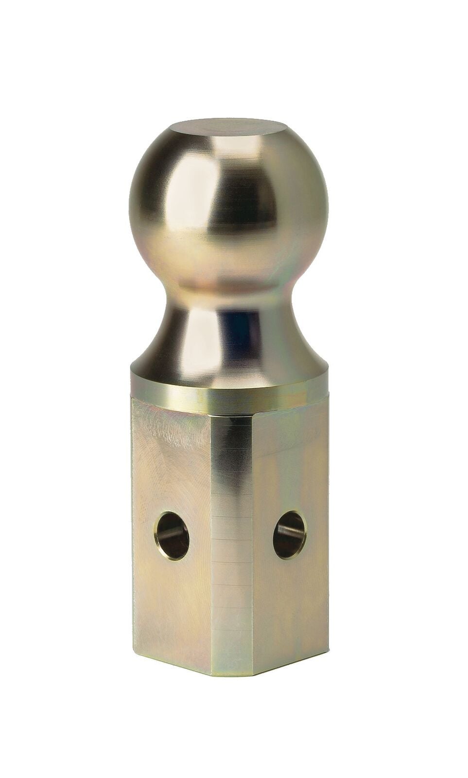
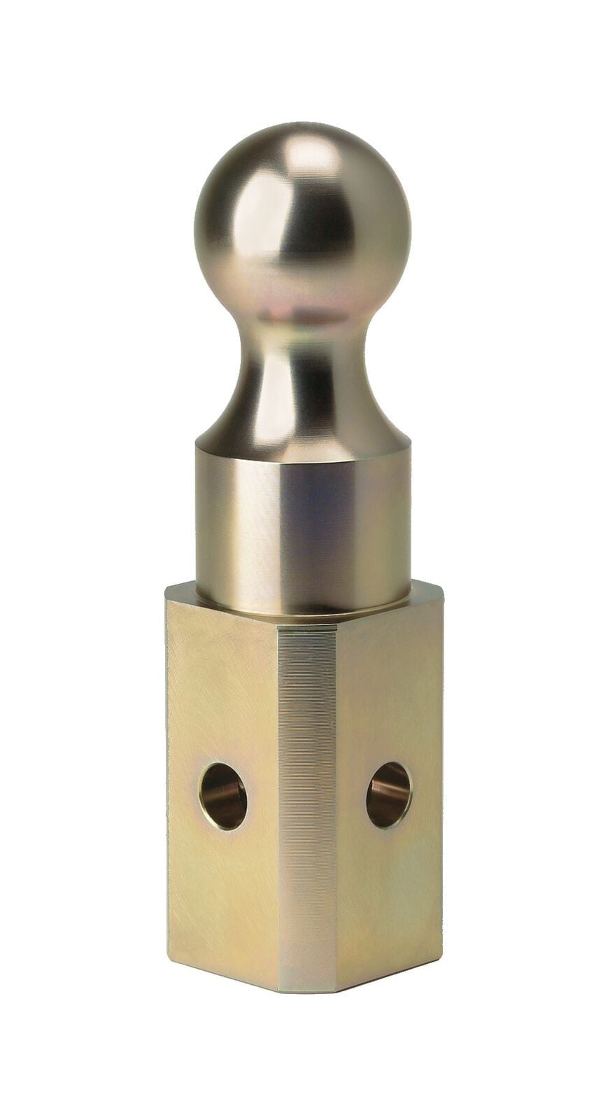
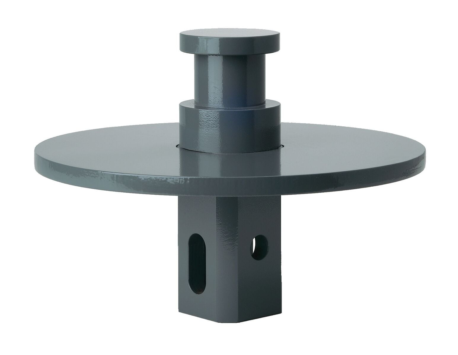
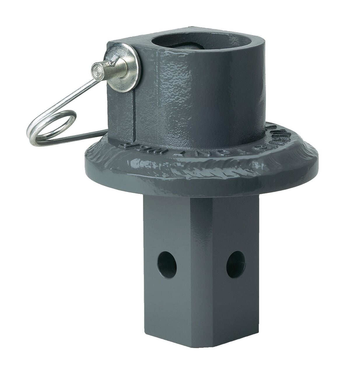
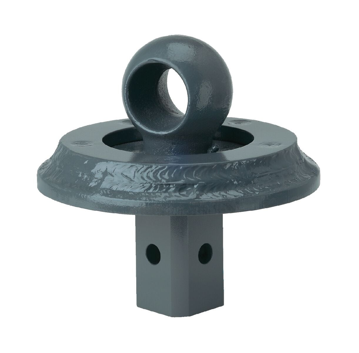
B&W Trailer Hitches 2-5/16" Replacement Ball For Turnoverball Gooseneck Trailer Hitch Ball GNXA2000B&W Trailer Hitches$86.00In Stock
View productOur in-house experts typically reply within one business day.

B&W Trailer Hitches
Verify Fitment
Select your vehicle to confirm this part fits.
2001 - 2006 Chevrolet Silverado 3500
Confirmed to Fit
2007 Chevrolet Silverado 3500 Classic
Confirmed to Fit
2001 - 2006 GMC Sierra 3500
Confirmed to Fit
Confirmed to Fit

Always the correct part
We know our products
Quality Products
Free Shipping!
Always the correct part
We know our products
Quality Products
Free Shipping!
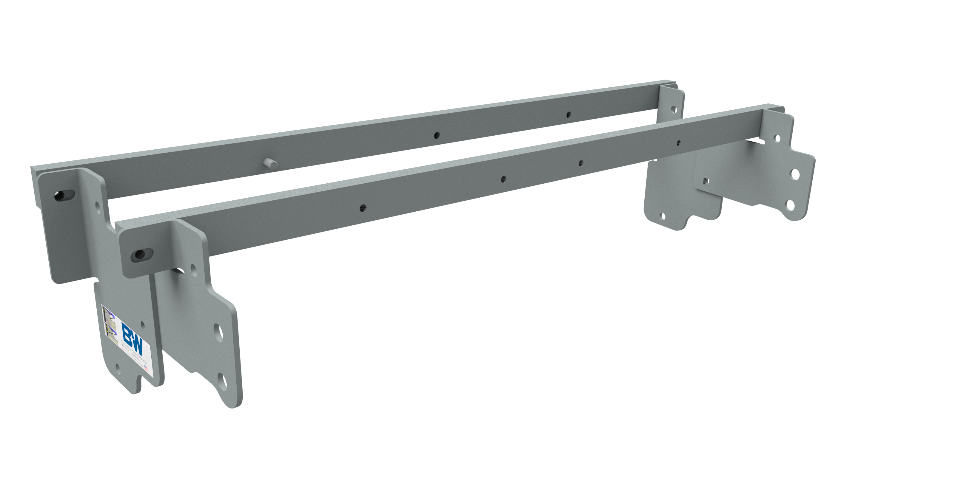
Effortlessly set up your B&W Turnoverball gooseneck trailer hitch center section (BQVLGNRC962 - not included) with our custom-designed installation kit.
Upgrade your towing capabilities with our B&W Under-Bed Installation Kit for Turnoverball Gooseneck. Designed for quick and easy installation, this kit is the perfect companion for your B&W Turnoverball gooseneck trailer hitch center section (BQVLGNRC962 - not included).

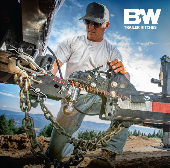
B&W Trailer Hitches is an American manufacturer known for durable, innovative towing products, including gooseneck hitches, fifth-wheel hitches, receiver hitches, and ball mounts. Built in Kansas by employee-owners, B&W products are engineered for dependable performance, easy installation, and long-lasting quality.
B&W Trailer Hitches is an American manufacturer known for building innovative, dependable towing products designed to make hitching easier and towing more comfortable. The company began in 1987 in Humboldt, Kansas, when founders Roger Baker and Joe Works combined their fabrication experience to build custom truck beds and solve common problems faced by truck owners.
B&W changed the gooseneck hitch industry with the introduction of the Turnoverball Gooseneck Hitch. Its under-bed mounting system and reversible hitch ball allowed truck owners to quickly store the ball beneath the bed, leaving a clean and unobstructed surface when the hitch was not in use. B&W later applied the same practical approach to the Companion Fifth Wheel Hitch, creating a removable fifth-wheel hitch engineered for a quiet, smooth, and secure towing experience.
Today, B&W manufactures gooseneck hitches, fifth-wheel hitches, receiver hitches, ball mounts, and towing accessories at its nearly 600,000-square-foot facility. The company is owned by approximately 500 employee-owners who remain committed to American manufacturing, trusted materials, skilled craftsmanship, and long-lasting product quality.
Whether you are towing a work trailer, livestock trailer, camper, or fifth wheel, B&W Trailer Hitches offers thoughtfully engineered towing equipment built to perform mile after mile.
Experts available to answer your questions
Call 888-634-94944 compatible vehicles
| Year | Make & Model | Notes |
|---|---|---|
| 2001 - 2006 | Chevrolet Silverado 3500 | — |
| 2007 | Chevrolet Silverado 3500 Classic | — |
| 2001 - 2006 | GMC Sierra 3500 | — |
| 2007 | GMC Sierra 3500 Classic | — |
The B&W Trailer Hitches Turnoverball Mounting Kit Gooseneck Trailer Hitch Mount Kit BQVLGNRM1062 (Part #BQVLGNRM1062) fits 2001-2006 Chevrolet Silverado 3500 models. The 2007 model year is the last year covered by this part number. For newer models, check for an updated version.
Yes, the B&W Trailer Hitches Turnoverball Mounting Kit Gooseneck Trailer Hitch Mount Kit BQVLGNRM1062 (Part #BQVLGNRM1062) is designed to fit the 2001-2006 Chevrolet Silverado 3500.
The B&W Trailer Hitches Turnoverball Mounting Kit Gooseneck Trailer Hitch Mount Kit BQVLGNRM1062 (Part #BQVLGNRM1062) fits the following vehicles: 2001-2006 Chevrolet Silverado 3500; 2007 Chevrolet Silverado 3500 Classic; 2001-2006 GMC Sierra 3500; 2007 GMC Sierra 3500 Classic. Always verify your specific year, make, and model before ordering.
The B&W Trailer Hitches Turnoverball Mounting Kit Gooseneck Trailer Hitch Mount Kit BQVLGNRM1062 (Part #BQVLGNRM1062) Refer to the included instructions for installation details. Basic hand tools are typically all you need.
The Model 1062R is designed for 2001-2007 Chevrolet and GMC 1 Ton trucks with single or dual wheels, provided the truck has 2 bed cross members over the axle and is in original, as-manufactured condition. The manual states: "This product was designed to fit vehicles in their original, 'as manufactured' condition. Compatibility with vehicles having replacement parts, or other modifications is not guaranteed." Inspect your vehicle for modifications before installation. If your truck has been modified or you are unsure of the bed cross member configuration, contact B&W at 800.248.6564 or hitches@turnoverball.com for fitment verification.
Yes, you can drill through both the truck bed floor and a plastic bed liner. However, the manual notes that it is more difficult to accurately locate the midpoint between the fender wheel wells and to ensure the bed liner does not move while sawing the 4-inch hole. Take extra care to measure, mark, and cut carefully to ensure proper hitch alignment.
Before installation, you must remove: (1) the spare tire, (2) the heat shield in front of the back crossmember, (3) the heat shield at the back of the crossmember near the front of the wheel well, and (4) the lower exhaust bracket. To remove the exhaust bracket, pull the hanger rod out of the rubber bracket hole. A 6" to 8" wood block can then be positioned between the exhaust pipe and frame to increase clearance. Caution: the exhaust pipe may be hot.
The manual recommends removing the bed bolts on the driver's side and lifting the bed to give you more clearance during installation of the hitch parts under the bed floor. This is not a full bed removal but rather a partial lift to improve access and safety while working with fuel lines, brake lines, and electrical wires located along the frame rails.
The manual identifies several critical hazards: (1) Fuel lines, brake lines, and electrical wires are located along the frame rails and must not be damaged when positioning hitch components, drilling holes, tightening fasteners, or lifting and lowering the truck bed. (2) The fuel tank vent, located on top of the gas tank, can be easily damaged during installation of hitch components. (3) The exhaust pipe may be hot. (4) Care must be taken when positioning the front crossmember and center section components. Carefully examine the location of all these components before installation.
Yes. An overhead lifting device such as chain falls, engine hoist, or cable come-a-long can be used to lift the center section into place. Lower a loop of rope or chain through the 4" hole in the truck bed floor and attach it to the latch pin in the round hitch receiver tube in the center section. Use the lifting device to raise the center section until the round hitch receiver tube fits in the 4" hole. Maintaining upward pressure may facilitate fastening the crossmember to the center section, especially if the truck bed floor has been distorted. However, the lifting device must be disconnected before squaring the center section across the frame, installing the sideplates, and torquing fasteners.
For an 8-foot long bed, measure 49 1/2" from the back end (tail gate end) of the truck bed floor by hooking a tape measure over the back of the sheet metal and marking the floor at that measurement. Center the measurement between the fender wheel wells. This location is critical to correct installation. Measure, mark, and saw carefully. You can make the 4-inch hole using a four-inch hole saw or by marking a 4-inch circle and cutting it out with a saber saw equipped with a metal cutting blade.
Yes. To install the safety chain brackets, you must drill four 1/2" holes through the truck bed floor. Drill the holes from beneath the truck, through the two holes located on each side of the round receiver tube in the center section. This will locate the safety chain brackets in the lowest point of the floor corrugation. Drop a U-bolt through each pair of holes from the topside of the truck bed floor.
The 1062R includes the Center Box (GNRC962) containing: 1 center section, 2 U-bolts (1/2" X 8-1/4"), 1 ball (2-5/16"), 1 latch pin handle, 2 bushing blocks, and a Mounting Kit Bolt Bag with: 4 carriage bolts (1/2" X 1-1/4"), 6 cap screws (1/2" X 1-1/2"), 4 cap screws (1/2" X 2-1/4"), 11 flat washers (1/2"), 19 lock washers (1/2"), 13 finish nuts (1/2"), 2 cap screws (3/4" X 2-1/2"), 2 lock washers (3/4"), 2 finish nuts (3/4"), plus hardware for the safety chain kit. The Mounting Kit Box (GNRM1062) contains 4 sideplates and 2 crossmembers.
The manual does not specify a complete list of required tools. However, based on the installation steps, you will need: a tape measure, a 4-inch hole saw or saber saw with metal cutting blade, wrenches or sockets to fit 1/2" and 3/4" bolts, a torque wrench (for torque specifications of 60, 80, and 120 ft-pounds), and a drill with a 1/2" bit (for safety chain bracket holes). An overhead lifting device such as a chain fall or engine hoist is recommended but not required. Contact B&W at 800.248.6564 for a complete tool list.
The installation sequence is: (1) Remove spare tire and heat shields. (2) Remove exhaust bracket. (3) Mark and cut the 4-inch hole in the truck bed floor. (4) Install crossmembers (front and rear). (5) Install center section. (6) Install sideplates. (7) Install latch pin release handle. (8) Install safety chain brackets. (9) Engage latch pin. Follow each step in order as detailed in the manual, as later steps depend on earlier ones being completed correctly.
Install the front crossmember by sliding it across the frame rails between the two bed cross members where the 4-inch hole has been cut. Center it between the frame rails, then rotate it so the pressed bolt is above the fuel tank and threads face toward the rear. Push it forward on the frame toward the front bed crossmember on the higher part of the frame. Rotate before moving forward, as rotation is difficult on the higher frame. Install the rear crossmember between the double bed crossmembers by pushing it in horizontally until centered, then rotate it to vertical with threaded holes at the bottom. Position it right behind the bed crossmember closest to the 4-inch hole.
Raise the center section with the socket top pointed upward and the latch pin to the driver's side. Raise it over the differential and angle it up over the exhaust pipe until it clears the fuel tank, then move it back over the fuel tank. Hold the center section tightly against the bottom of the truck bed floor to avoid damaging fuel lines and wiring from the top of the fuel tank. Insert the socket top into the 4-inch hole. Move the front bar against the center section, sliding the pressed bolt into the matching hole. Install two 2-1/4" x 1/2" bolts through the bar and into the center section with flat washer, lock washer, and nut on each. Thread four 1-1/2" bolts with flat and lock washers through the center section into the rear bar. Shift the bar sideways to center it across the frame and twist the assembly parallel with the bed crossmembers. Tighten all center section fasteners at this time.
Install the sideplates with the bent flange to the front and large holes to the rear. Attach the two pieces of each sideplate together with 1/2" carriage bolts inserted into the square holes from the backside and fastened with lock washer and nut. Attach the flange on the sideplate to the front bar by placing a 1/2" x 2-1/4" bolt through the bar and sideplate; secure with flat washer, lock washer, and nut. Attach the rear bar to the sideplate flange by threading a 1/2" x 1-1/2" bolt into the bar and tighten both front and rear flanges to 80 ft-pounds. Install the 1/2" x 8-1/4" U-bolt from inside the frame through the holes in the sideplate above and below the frame, using lock washer and nut on each end. Install the 3/4" x 2-1/2" bolt through the lower rear hole in the sideplate using the frame insert provided to convert the slotted frame hole to a 3/4" round hole. Repeat on the passenger side.
Insert the latch pin release handle through the slot in the end of the center section on the driver's side of the truck. Align the handle eyelet with the square hole in the latch pin so the handle is in line with the latch pin. Secure the handle to the pin with the 5/16" X 3/4" carriage bolt and 5/16" locking flange nut. The included 5/16" cap screw can replace the carriage bolt if wrench access on the cab side of the handle is limited. Tighten the nut until secure but do not over-tighten and deform the handle eyelet. The latch pin will not function properly if the handle is not installed correctly.
Retract the latch pin by pulling the handle all the way out until it stops, then rotate it clockwise. Place the 2-5/16" ball in the hitch receiver. Engage the latch pin by rotating the handle counter-clockwise. Be certain the latch pin passes through the holes in the 2-5/16" ball and fully engages through the hitch receiver. Finally, remove and lightly grease the four corners on the square base of the 2-5/16" ball.
The torque specifications are: (1) Front and rear flange bolts (1/2" x 1-1/2" and 1/2" x 2-1/4"): 80 ft-pounds. (2) 3/4" side plate bolts: 120 ft-pounds. (3) Frame clamping U-bolts (1/2" x 8-1/4"): 60 ft-pounds, tightened slowly while alternating between top and bottom legs until equally tightened. (4) Carriage bolts connecting sideplate pieces: 60 ft-pounds. Tighten fasteners in this order: front and rear flanges first, then 3/4" side plate bolts, then U-bolts, then carriage bolts.
The manual states to tighten the lock nuts on the safety chain bracket U-bolts "until flush with the bottom of the U-bolts" but does not specify a torque value in foot-pounds. Contact B&W at 800.248.6564 or hitches@turnoverball.com for the specific torque specification.
The manual does not specify a torque value for the 5/16" X 3/4" carriage bolt or 5/16" cap screw securing the latch pin handle. It states to "tighten the nut until it is secure" but warns "do not over-tighten and deform the handle eyelet." Contact B&W at 800.248.6564 or hitches@turnoverball.com for the specific torque specification.
The manual notes that 2004 and newer model trucks equipped with gas engines have a new fuel valve mounted on the rear of the fuel tank that makes it more difficult to install the Turnoverball™ center section. This fuel valve can be easily removed and replaced to ease installation. The manual provides four steps: (1) Locate the fuel valve. (2) Disengage the locking pin. (3) Slide fuel valve from bracket. (4) Install Turnoverball™ Center Section. (5) Replace fuel valve to bracket on fuel tank. Follow these steps before installing the center section.
The rear sideplate has a 3/4" x 2-1/2" bolt that goes through the lower rear hole. The hole in the frame is a slotted hole. B&W provides an insert to convert the slotted frame hole to a 3/4" round hole. The insert can be positioned in three different positions: center position on one side, and offset position on the other side (offset either forward or rearward). Look at the position of the sideplate hole relative to the frame slot to select the appropriate position for the frame insert. Install the insert over the 3/4" bolt and into the frame, then install the flat washer, lock washer, and nut.
After installation, make certain the hitch is square with the frame. Verify that all fasteners have been tightened to the specified torque values: front and rear flanges to 80 ft-pounds, 3/4" side plate bolts to 120 ft-pounds, U-bolts to 60 ft-pounds (alternating between top and bottom legs), and carriage bolts to 60 ft-pounds. Verify that the latch pin fully engages through the hitch receiver and that the latch pin handle is installed correctly and in line with the latch pin. Lightly grease the four corners on the square base of the 2-5/16" ball. Check that no fuel lines, brake lines, or electrical wires have been damaged during installation.
The manual does not specify the towing capacity of the 1062R. However, it includes a critical warning: "The tow vehicle's towing capacities should under NO circumstances be exceeded." Consult your truck's owner's manual or contact B&W at 800.248.6564 for the towing capacity of your specific truck and hitch combination.
The manual specifies one maintenance step: after engaging the latch pin and installing the 2-5/16" ball, remove and lightly grease the four corners on the square base of the 2-5/16" ball. The manual does not provide a maintenance schedule or other maintenance requirements. Contact B&W at 800.248.6564 or hitches@turnoverball.com for a complete maintenance schedule.
Yes, if your truck is a 2001-2007 Chevrolet or GMC 1 Ton (single or dual wheel) with 2 bed cross members over the axle and is in original, as-manufactured condition. Vehicles with modifications may not be compatible. Inspect your truck before purchase.
Remove the spare tire, heat shields (in front of and behind the back crossmember), and the lower exhaust bracket. Lift the truck bed on the driver's side for clearance. An overhead lifting device is recommended but not required.
Yes. You must cut a 4-inch hole in the truck bed floor at 49 1/2" from the tail gate (for an 8-foot bed), centered between the fender wheel wells. Use a 4-inch hole saw or saber saw with metal cutting blade. This location is critical to correct installation.
Front and rear flange bolts: 80 ft-pounds. Side plate bolts (3/4"): 120 ft-pounds. Frame U-bolts: 60 ft-pounds (alternating top and bottom). Carriage bolts: 60 ft-pounds. Use a torque wrench and tighten in the order specified in the manual.
Pull the handle all the way out and rotate clockwise to retract the latch pin. Place the 2-5/16" ball in the receiver. Rotate the handle counter-clockwise to engage the latch pin through the ball. Verify full engagement and lightly grease the four corners of the ball base.
The tow vehicle's towing capacities must not be exceeded. Fuel lines, brake lines, and electrical wires along the frame rails must not be damaged during installation. The fuel tank vent can be easily damaged. Carefully examine all these locations before installation.
The manual does not state whether professional installation is required or recommended. It recommends reading the instructions before beginning and offers installation support at 800.248.6564 or hitches@turnoverball.com. Contact B&W to discuss your installation experience.
The manual warns: "LATCH PIN WILL NOT FUNCTION PROPERLY IF HANDLE IS NOT INSTALLED CORRECTLY." Verify that the latch pin release handle is inserted through the slot in the end of the center section on the driver's side, and that the handle eyelet is aligned with the square hole in the latch pin so the handle is in line with the latch pin. Ensure the handle is secured with the 5/16" X 3/4" carriage bolt and 5/16" locking flange nut, tightened until secure but not over-tightened. Also verify that the latch pin passes through the holes in the 2-5/16" ball and fully engages through the hitch receiver.
After installing the center section and sideplates, shift the bar sideways until it is centered across the frame and twist the assembly so that it is parallel with the bed crossmembers before tightening all fasteners. If the hitch is not square after tightening, loosen the fasteners, reposition the hitch to be square with the frame, and re-tighten to the specified torque values. Verify that the hitch is square before final tightening.
Free Shipping
Ships free on all orders
 Authorized Dealer

Quick Ship
In stock and ready to ship — order now!
FREE ShippingFREE SHIPPING
Estimated delivery Sat, Sep 19 - Tue, Sep 22
Order before 2 PM EST Monday–Friday for same-day processing
Guaranteed safe & secure checkout
No reviews have been added for this product.