
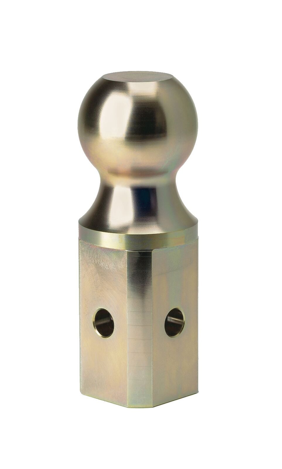
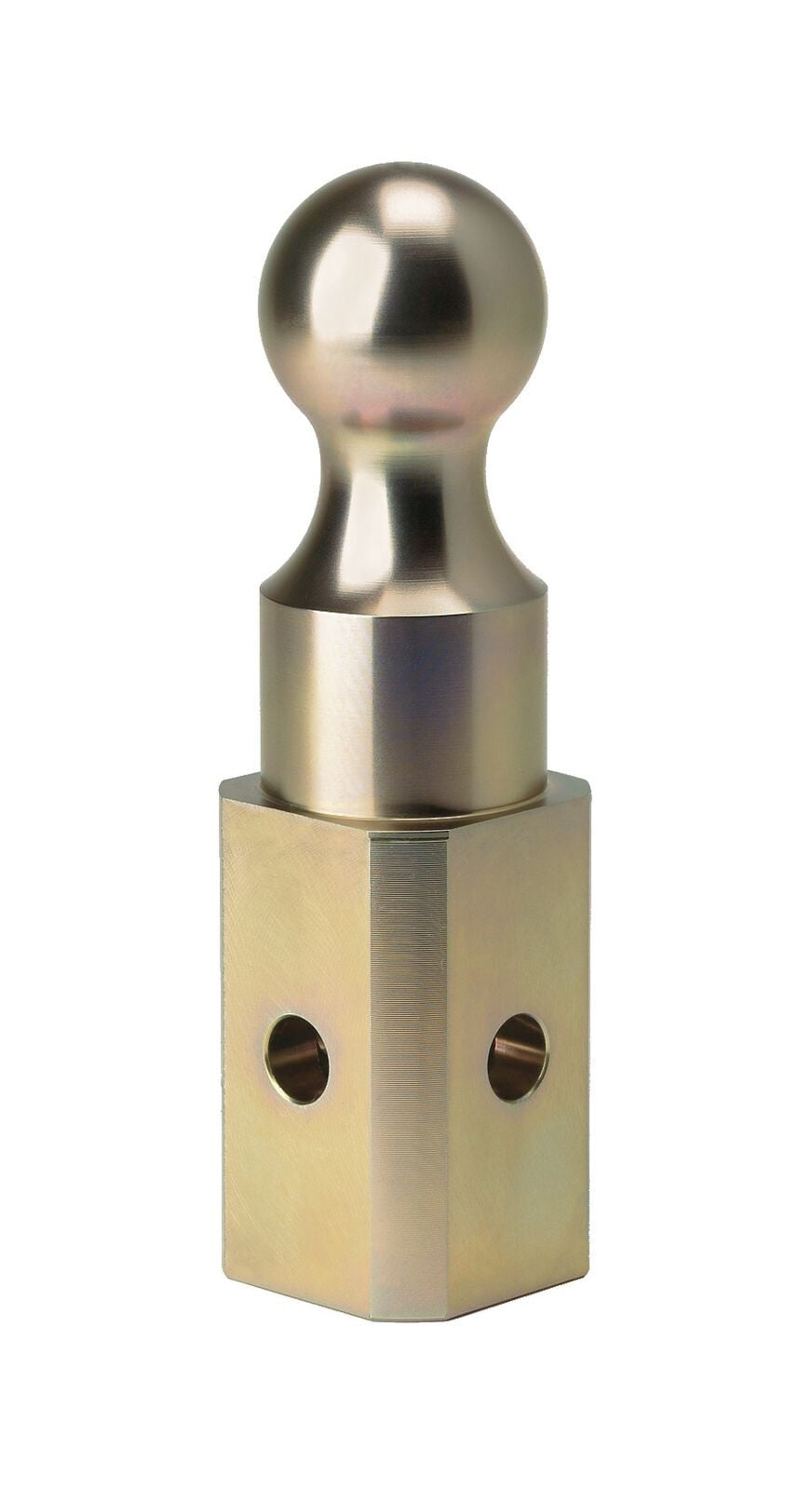
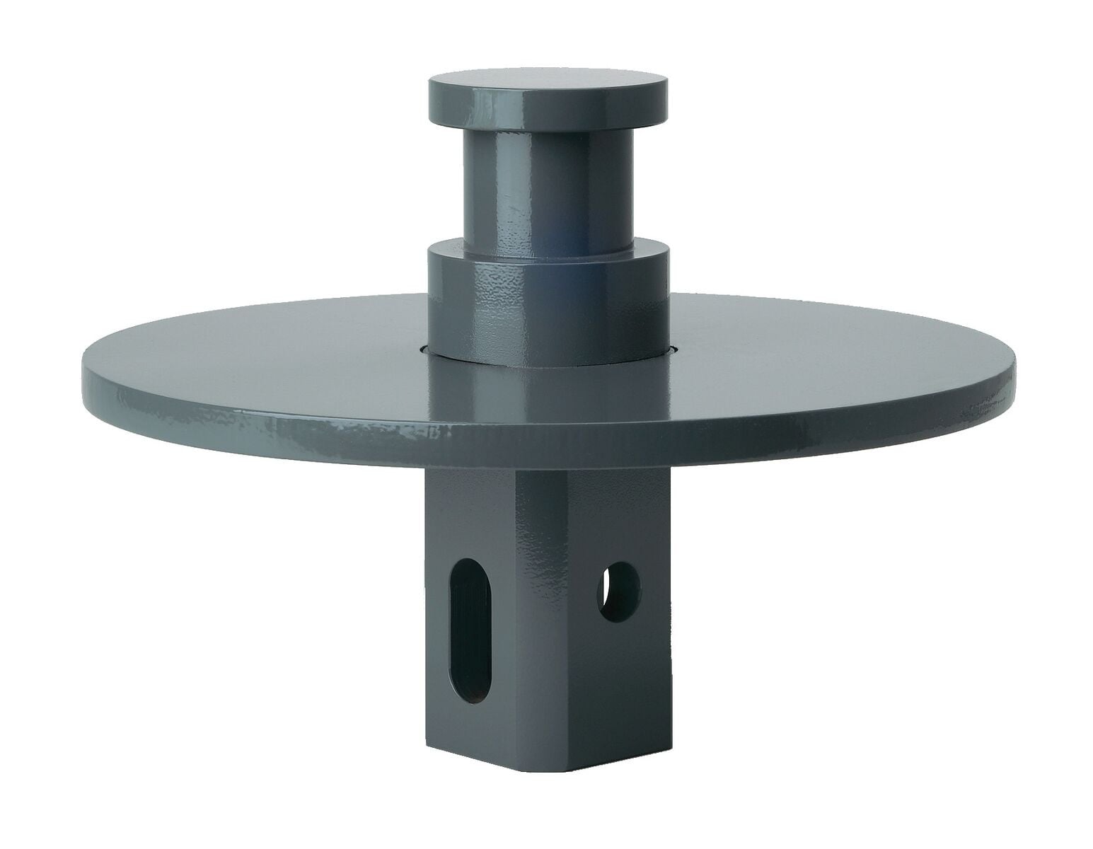
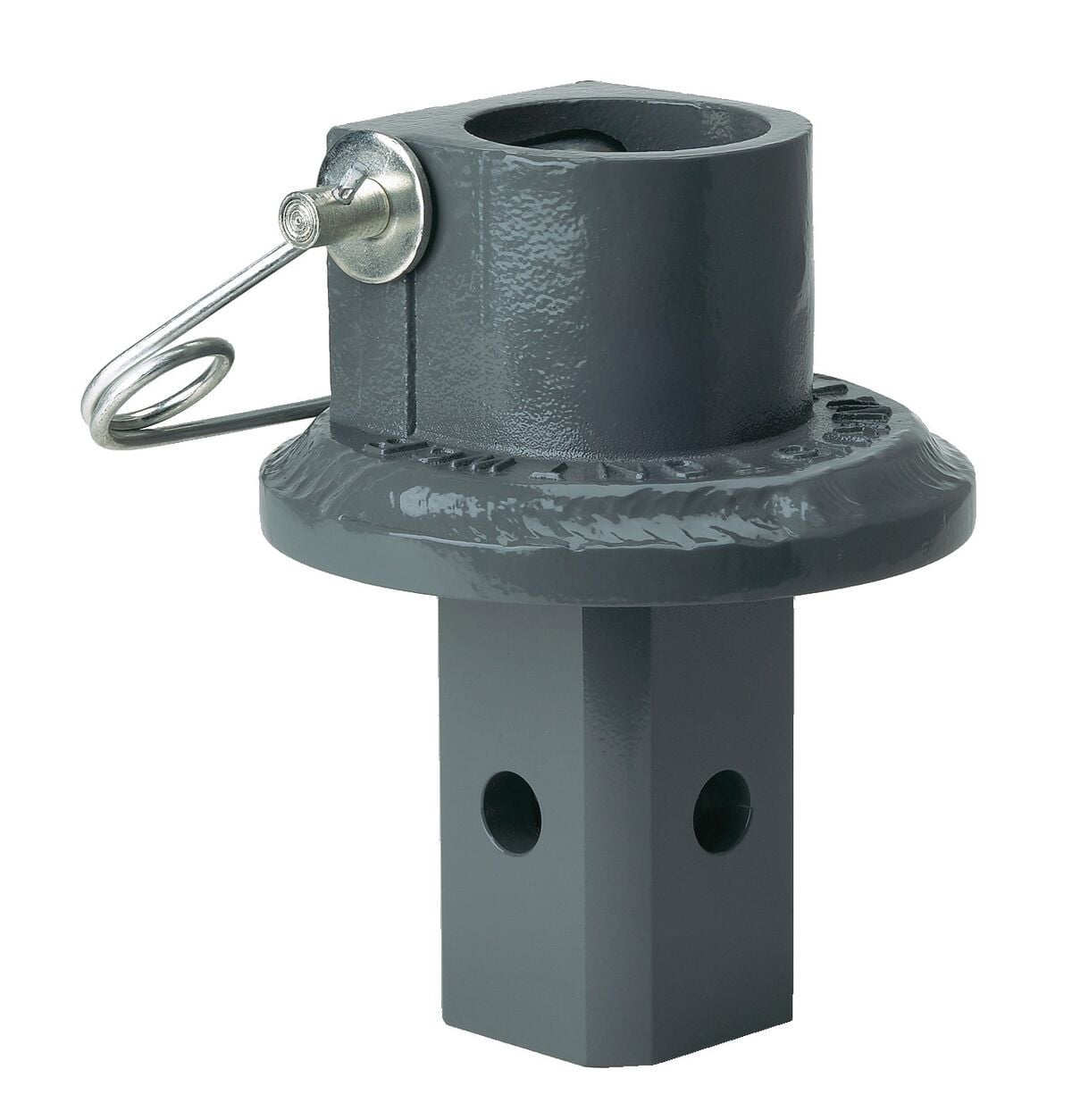
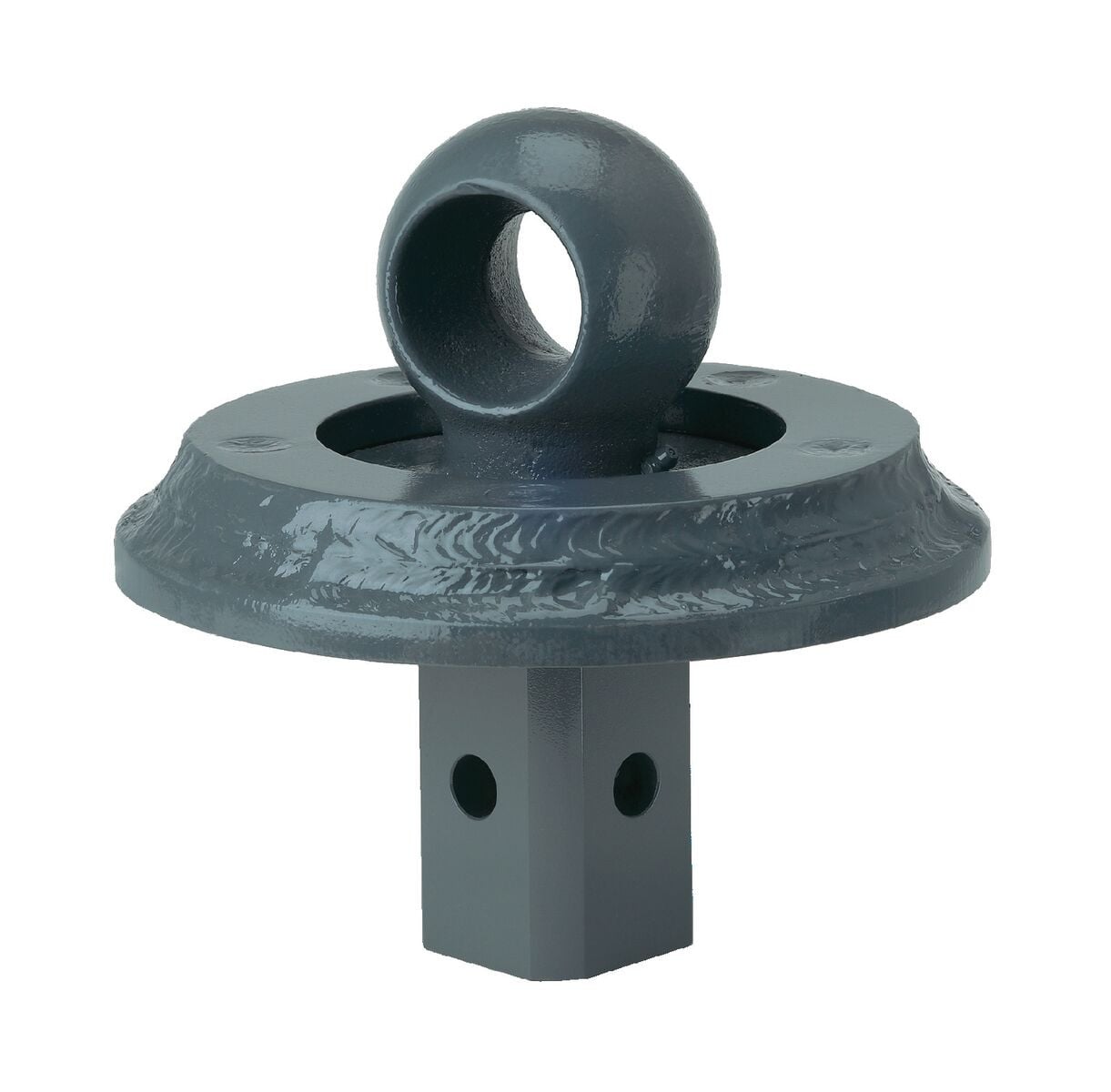
B&W Trailer Hitches 2-5/16" Replacement Ball For Turnoverball Gooseneck Trailer Hitch Ball GNXA2000B&W Trailer Hitches$86.00In Stock
View productOur in-house experts typically reply within one business day.

B&W Trailer Hitches
Verify Fitment
Select your vehicle to confirm this part fits.
2001 - 2010 Chevrolet Silverado 2500 HD
Confirmed to Fit
2007 Chevrolet Silverado 2500 HD Classic
Confirmed to Fit
2007 - 2010 Chevrolet Silverado 3500
Confirmed to Fit
2007 - 2010 Chevrolet Silverado 3500 HD
Confirmed to Fit
2001 - 2010 GMC Sierra 2500 HD
Confirmed to Fit
2007 GMC Sierra 2500 HD Classic
Confirmed to Fit
2007 - 2010 GMC Sierra 3500 HD
Confirmed to Fit

Always the correct part
We know our products
Quality Products
Free Shipping!
Always the correct part
We know our products
Quality Products
Free Shipping!
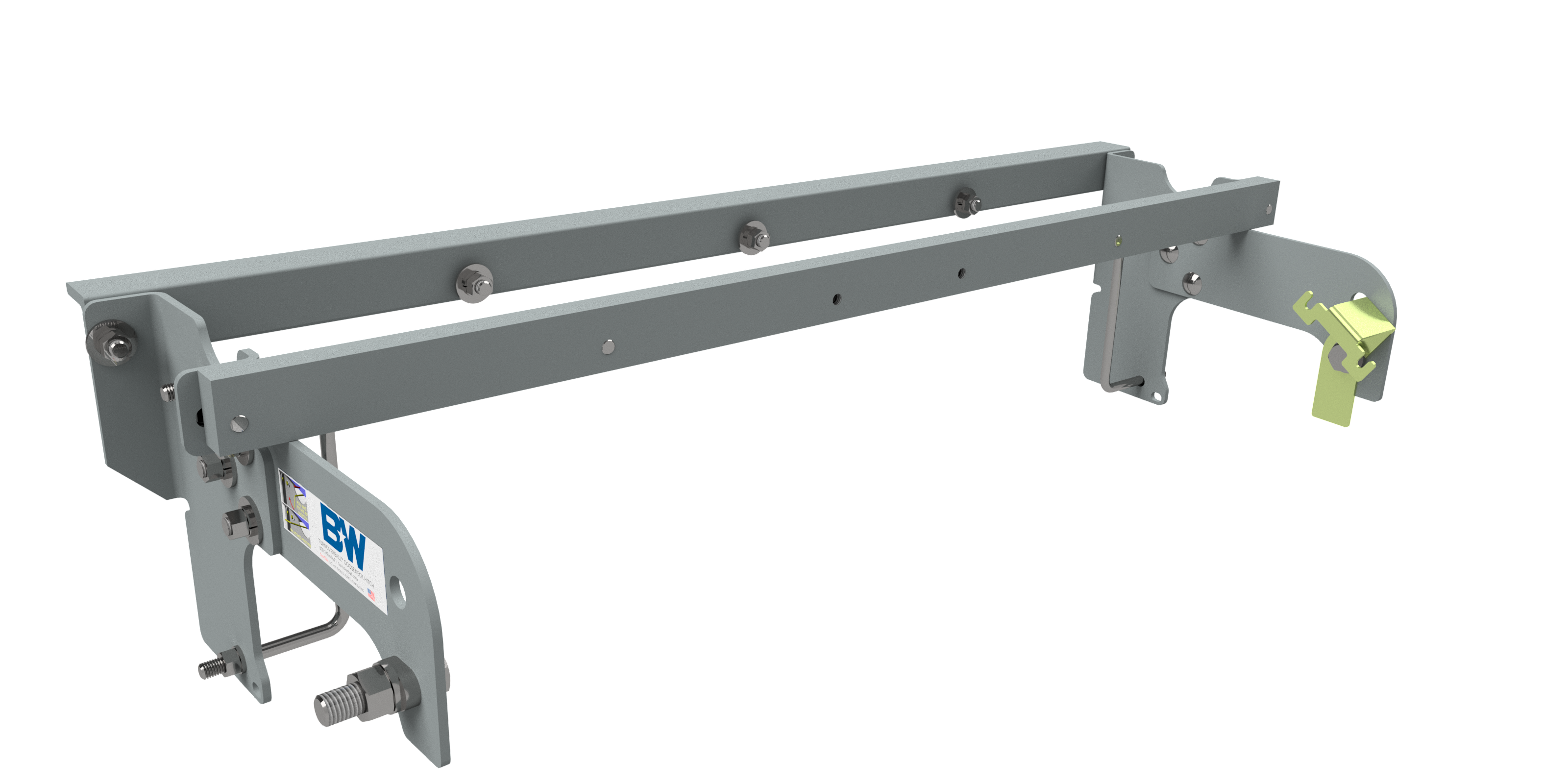
Effortlessly set up your B&W Turnoverball gooseneck trailer hitch center section (BQVLGNRC959 - not included) with our custom-designed, under-bed installation kit.
Upgrade your towing capabilities with our B&W under-bed installation kit for Turnoverball gooseneck. Designed for durability and ease of use, this kit is the perfect addition to your towing setup.

B&W Trailer Hitches is an American manufacturer known for durable, innovative towing products, including gooseneck hitches, fifth-wheel hitches, receiver hitches, and ball mounts. Built in Kansas by employee-owners, B&W products are engineered for dependable performance, easy installation, and long-lasting quality.
B&W Trailer Hitches is an American manufacturer known for building innovative, dependable towing products designed to make hitching easier and towing more comfortable. The company began in 1987 in Humboldt, Kansas, when founders Roger Baker and Joe Works combined their fabrication experience to build custom truck beds and solve common problems faced by truck owners.
B&W changed the gooseneck hitch industry with the introduction of the Turnoverball Gooseneck Hitch. Its under-bed mounting system and reversible hitch ball allowed truck owners to quickly store the ball beneath the bed, leaving a clean and unobstructed surface when the hitch was not in use. B&W later applied the same practical approach to the Companion Fifth Wheel Hitch, creating a removable fifth-wheel hitch engineered for a quiet, smooth, and secure towing experience.
Today, B&W manufactures gooseneck hitches, fifth-wheel hitches, receiver hitches, ball mounts, and towing accessories at its nearly 600,000-square-foot facility. The company is owned by approximately 500 employee-owners who remain committed to American manufacturing, trusted materials, skilled craftsmanship, and long-lasting product quality.
Whether you are towing a work trailer, livestock trailer, camper, or fifth wheel, B&W Trailer Hitches offers thoughtfully engineered towing equipment built to perform mile after mile.
Experts available to answer your questions
Call 888-634-94947 compatible vehicles
| Year | Make & Model | Notes |
|---|---|---|
| 2001 - 2010 | Chevrolet Silverado 2500 HD | — |
| 2007 | Chevrolet Silverado 2500 HD Classic | — |
| 2007 - 2010 | Chevrolet Silverado 3500 | — |
| 2007 - 2010 | Chevrolet Silverado 3500 HD | — |
| 2001 - 2010 | GMC Sierra 2500 HD | — |
| 2007 | GMC Sierra 2500 HD Classic | — |
| 2007 - 2010 | GMC Sierra 3500 HD | — |
Yes, the B&W Trailer Hitches Turnoverball Mounting Kit Gooseneck Trailer Hitch Mount Kit BQVLGNRM1067 (Part #BQVLGNRM1067) is designed to fit the 2001-2010 Chevrolet Silverado 2500 HD.
The B&W Trailer Hitches Turnoverball Mounting Kit Gooseneck Trailer Hitch Mount Kit BQVLGNRM1067 (Part #BQVLGNRM1067) fits 2001-2010 Chevrolet Silverado 2500 HD models. The 2010 model year is the last year covered by this part number. For newer models, check for an updated version.
The B&W Trailer Hitches Turnoverball Mounting Kit Gooseneck Trailer Hitch Mount Kit BQVLGNRM1067 (Part #BQVLGNRM1067) fits the following vehicles: 2001-2010 Chevrolet Silverado 2500 HD; 2007 Chevrolet Silverado 2500 HD Classic; 2007-2010 Chevrolet Silverado 3500; 2007-2010 Chevrolet Silverado 3500 HD; 2001-2010 GMC Sierra 2500 HD; 2007 GMC Sierra 2500 HD Classic; 2007-2010 GMC Sierra 3500 HD. Always verify your specific year, make, and model before ordering.
The B&W Trailer Hitches Turnoverball Mounting Kit Gooseneck Trailer Hitch Mount Kit BQVLGNRM1067 (Part #BQVLGNRM1067) Refer to the included instructions for installation details. Basic hand tools are typically all you need.
The 1067R fits 2001-2010 Chevrolet and GMC 3/4 Ton HD trucks in both long and short bed configurations, and 2007-2010 Chevrolet and GMC 1 Ton trucks with one bed crossmember over the axle. The product was designed for vehicles in original, as-manufactured condition. If your truck has replacement parts or other modifications, compatibility is not guaranteed—inspect your vehicle before installation.
Yes, the 1067R is designed for both long and short bed trucks. However, before installing, you must check for adequate turning clearance between the front of all your trailers and the truck cab. On short bed trucks, this clearance is more limited and must be verified before installation.
The mounting kit (GNRM1067) includes: driver and passenger side front and rear sideplates, front and rear crossmembers, relay bracket, two 8-1/4" × 4-1/4" × 1/2" U-bolts, rear sideplate bushings, and a bolt bag containing carriage bolts, cap screws, flat washers, lock washers, finish nuts, and an O-ring. The center section box (GNRC959N) contains the center section, 2-5/16" ball, latch pin handle, U-bolts, conical springs, and additional fasteners.
Yes. Step One requires removing the spare tire. You must also remove or cut out a section of the heat shield under the bed floor to allow the hitch assembly to be installed. The heat shield in front of the back crossmember and the heat shield at the back of the crossmember near the front of the wheel well must both be addressed.
Yes. Step Two requires removing the lower exhaust bracket to ease installation of the center section. Pull the hanger rod out of the rubber bracket hole. A 6" to 8" wood block can then be positioned between the exhaust pipe and frame to increase clearance between the top of the exhaust pipe and the bottom of the truck bed floor. Caution: the exhaust pipe may be hot. The exhaust bracket is reinstalled in Step Twelve after the hitch is in place.
Yes. You must drill a 4-inch hole in the truck bed floor (Step Three) and four 1/2-inch holes through the truck bed floor for the safety chain brackets (Step Eleven). The 4-inch hole location is critical: measure from the tailgate end of the truck bed floor and center between the wheel wells. For long beds, the hole is 49 1/2" from the back; for short beds, 44 1/4". The four 1/2-inch holes are drilled from beneath the truck through the two holes on each side closest to the round receiver tube.
Use a 4-inch hole saw, or alternatively mark a 4-inch circle and cut it out with a saber saw equipped with a metal cutting blade. B&W recommends using a 3/4-inch piece of plywood as a drilling guide to prevent the hole saw from moving while drilling.
Yes. Step Four requires making a small notch in the sheet metal flange that hangs down from the bottom of the truck bed floor on the passenger side. Locate the center truck bed cross member, measure 2 1/2" from the front, and mark a 1" wide by 1/2" tall notch. Remove the marked metal using sheet metal shears. This allows the front angle iron crossmember to be installed.
Possibly. In some truck models, plastic wheel well liners extend past the side plate installation location on the frame. A portion of the liner may need to be cut away over the area where the side plate will be installed. Inspect your truck before installation.
Yes, but additional steps are required. Beginning in 2007, some models have a factory-installed trailer brake system with a relay that must be relocated before the driver's side sideplate can be installed. If the relay is present, loosen the two bolt heads above the large oval hole in the frame on the driver's side and slide the relay to detach it. Beginning in 2009, models also have a wiring clip attached to the bottom of the frame on both sides just ahead of the axle that must be removed and relocated. Step 8A provides detailed instructions for relocating the relay bracket.
Beginning in 2004, trucks equipped with gas engines have a fuel valve mounted on the rear of the fuel tank that can make center section installation more difficult. The fuel valve can be easily removed and replaced to ease installation. The manual provides step-by-step instructions: locate the fuel valve, disengage the locking pin, slide the fuel valve from the bracket, install the center section, then replace the fuel valve to the bracket.
Required tools include: a 4-inch hole saw or saber saw with metal cutting blade, sheet metal shears, a torque wrench (for torque specifications ranging from 40 to 120 ft-lbs), wrenches or sockets for 1/2-inch and 3/4-inch fasteners, and a drill for the 1/2-inch safety chain bracket holes. An overhead lifting device such as chain falls, engine hoist, or cable come-a-long is recommended to lift the center section into place. A 3/4-inch piece of plywood is recommended as a drilling guide.
An overhead lifting device is not required but is recommended. A chain falls, engine hoist, or cable come-a-long can be used to lift the center section into place. If used, lower a loop of rope or chain through the 4-inch hole in the truck bed floor and attach it to the latch pin in the round hitch receiver tube. Use the lifting device to raise the center section until the round hitch receiver tube fits in the 4-inch hole. The lifting device should be disconnected before squaring the center section across the frame, installing the sideplates, and torquing fasteners.
Before installation, carefully examine the location of fuel lines, brake lines, and electrical wires along the frame rails. Be certain you will not damage these components when positioning hitch components, drilling holes, and tightening fasteners. Pay special attention to the fuel tank vent located on top of the gas tank, which can be easily damaged during installation of the hitch components, particularly when positioning the front crossmember and center section. Also verify that your truck is in original, as-manufactured condition, as compatibility with vehicles having replacement parts or other modifications is not guaranteed.
Tighten fasteners in this order: (1) Center section bolts to crossmembers: 80 ft-lbs. (2) 3/4-inch sideplate bolts: 120 ft-lbs. (3) Frame clamping U-bolts: maximum 40 ft-lbs, tightened slowly while alternating between top and bottom legs until equally tightened. (4) Three carriage bolts on each sideplate: 60 ft-lbs. (5) Sideplates to front crossmembers: 80 ft-lbs. For safety chain U-bolts, tighten lock nuts until 1/4-inch of thread extends through the lock nut.
No. Do not invert the ball in the socket when carrying heavy loads on 2-wheel drive trucks. The ball may hit the top of the differential. Remove the ball from the socket before loading. A plug for the socket is available from B&W.
The tow vehicle's towing capacities should under no circumstances be exceeded. Refer to your vehicle manufacturer's specifications for the maximum towing capacity of your specific truck model.
The center section must be positioned with the receiver socket facing to the rear and the latch pin release arm on the driver's side. The round hitch receiver that protrudes from the top of the center section must fit through the 4-inch hole in the truck bed floor. Raise the center section into position between the crossmembers and carefully move it above the fuel tank from beneath the truck.
Insert the latch pin release handle through the slot in the end of the center section on the driver's side. Align the handle eyelet with the square hole in the latch pin so the handle is in line with the latch pin. Secure the handle to the pin with the 5/16" × 3/4" carriage bolt and 5/16" locking flange nut. The included 5/16" cap screw can replace the carriage bolt if wrench access on the cab side is limited. Tighten the nut until secure but do not over-tighten and deform the handle eyelet. The latch pin will not function properly if the handle is not installed correctly.
Retract the latch pin by pulling the handle all the way out until it stops, then rotate it clockwise. Place the 2-5/16" ball in the hitch receiver. Engage the latch pin by rotating the handle counter-clockwise. Be certain the latch pin passes through the holes in the 2-5/16" ball and fully engages through the hitch receiver. Finally, remove and lightly grease the four corners on the square base of the 2-5/16" ball.
To install the safety chain brackets, drill four 1/2-inch holes through the truck bed floor from beneath the truck, through the two holes located on each side closest to the round receiver tube in the center section. This locates the safety chain brackets in the lowest point of the floor corrugation. Drop a U-bolt through each pair of holes from the topside of the truck bed floor. Place a spring and lock nut on each of the four legs. Tighten the lock nuts until 1/4-inch of thread extends through the lock nut.
After installation, verify that the hitch is square with the frame before final torque. Ensure the latch pin fully engages through the hitch receiver and the 2-5/16" ball. Confirm that all fasteners have been tightened to the specified torque values in the correct sequence. Reinstall the exhaust hanger brackets and spare tire. Check that the latch pin release handle is properly installed and functions correctly.
Yes. After engaging the latch pin and installing the 2-5/16" ball, remove the ball and lightly grease the four corners on the square base of the ball.
The 1067R fits 2001-2010 Chevrolet and GMC 3/4 Ton HD trucks (long and short bed) and 2007-2010 1 Ton trucks with one bed crossmember over the axle. Your truck must be in original, as-manufactured condition.
Yes. Step One requires removing the spare tire and removing or cutting out sections of the heat shield under the bed floor. The exhaust bracket must also be removed in Step Two.
Center section to crossmembers: 80 ft-lbs. Sideplate bolts (3/4-inch): 120 ft-lbs. Frame clamping U-bolts: maximum 40 ft-lbs. Sideplate carriage bolts: 60 ft-lbs. Sideplates to front crossmembers: 80 ft-lbs.
No. Do not invert the ball when carrying heavy loads on 2WD trucks—the ball may hit the differential. Remove the ball from the socket before loading.
Pull the handle all the way out and rotate it clockwise to retract the pin. Place the 2-5/16" ball in the receiver. Rotate the handle counter-clockwise to engage the pin through the ball and receiver.
After tightening the center section bolts to the crossmembers to 80 ft-lbs, verify that the hitch is square with the frame before proceeding to tighten the sideplate bolts. If the hitch is not square, loosen the center section bolts, reposition the hitch to be square with the frame, and re-tighten to 80 ft-lbs.
Ensure the latch pin release handle is installed correctly. The handle eyelet must be aligned with the square hole in the latch pin so the handle is in line with the latch pin. The latch pin will not function properly if the handle is not installed correctly. Verify the handle is secured with the 5/16" × 3/4" carriage bolt and 5/16" locking flange nut, tightened until secure but not over-tightened. Retract the pin by pulling the handle all the way out until it stops and rotating it clockwise, then rotate counter-clockwise to engage.
Maintaining upward pressure on the center section may facilitate fastening the crossmember to the center section, especially if the truck bed floor has been distorted downward from heavy use. Use an overhead lifting device (chain falls, engine hoist, or cable come-a-long) to lift the center section into place. Lower a loop of rope or chain through the 4-inch hole in the truck bed floor and attach it to the latch pin in the round hitch receiver tube. Use the lifting device to raise the center section until the round hitch receiver tube fits in the 4-inch hole. The lifting device should be disconnected before squaring the center section across the frame and installing the sideplates.
Beginning in 2004, trucks equipped with gas engines have a fuel valve mounted on the rear of the fuel tank that can obstruct center section installation. The fuel valve can be easily removed and replaced. Locate the fuel valve, disengage the locking pin, and slide the fuel valve from the bracket. Install the center section, then replace the fuel valve to the bracket on the fuel tank.
Free Shipping
Ships free on all orders
 Authorized Dealer

Quick Ship
In stock and ready to ship — order now!
FREE ShippingFREE SHIPPING
Estimated delivery Sun, Sep 27 - Wed, Sep 30
Order before 2 PM EST Monday–Friday for same-day processing
Guaranteed safe & secure checkout
No reviews have been added for this product.