CURT Dual-Output Electrical Adapter (Adds 7-Way RV Blade to 4-Way Flat) Trailer Wiring Adapter ConnectorCURTOriginal price was $54.95. Current price is $47.99.In Stock
View productOur in-house experts typically reply within one business day.

Blue Ox



Always the correct part
We know our products
Quality Products
Free Shipping!
Always the correct part
We know our products
Quality Products
Free Shipping!
On Sale Today
Original price was $699.99. Current price is $82.50.You save $617.49 (88%)
Free Shipping
Ships free on all orders
 Authorized Dealer

Quick Ship
In stock and ready to ship — order now!
FREE ShippingFREE SHIPPING
Estimated delivery Fri, Oct 9 - Mon, Oct 12
Order before 2 PM EST Monday–Friday for same-day processing
Guaranteed safe & secure checkout

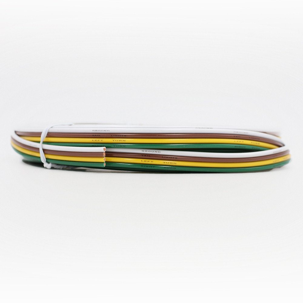
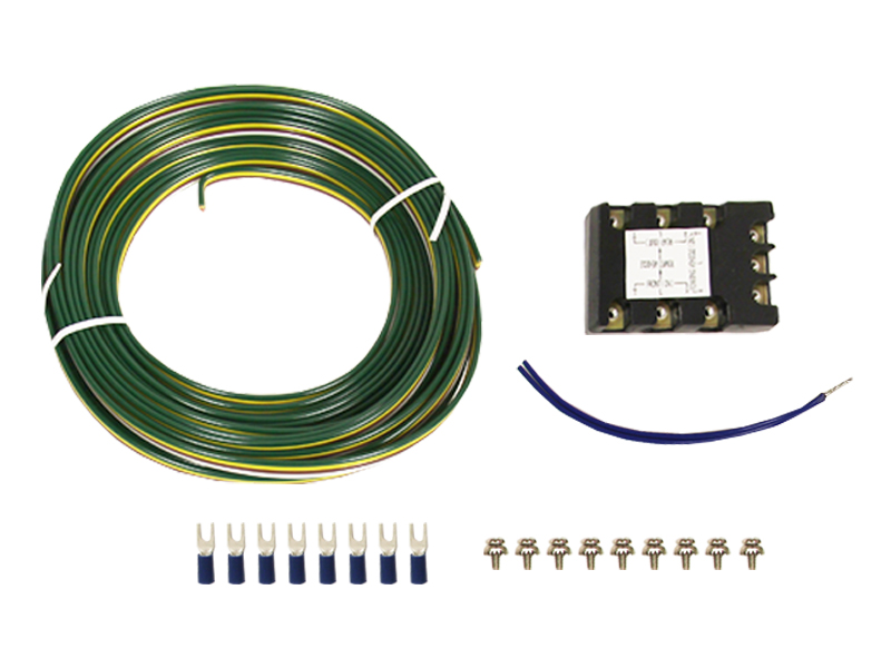
The kit includes a 26-foot wiring harness, providing ample length for flexible and convenient installation.
Installation Required Yes/No: Yes
2770: No
488: Yes
Wiring Harness Length: 26
The Blue Ox BX8811 TrlrWireInstKt is a top-tier solution for synchronizing the tail, brake, and turn signal lights of your RV with your towed vehicle. With an impressive length of 26 feet, this wiring harness ensures ample reach for easy and flexible installation. It is designed for those who crave seamless integration and safety on the road. The kit requires installation, but the process is straightforward to ensure you're quickly on your way to a more connected and safer towing experience.

Blue Ox is known internationally for recreational and commercial towing products, manufacturing in Pender, Nebraska since 1925. The line covers tow bars and vehicle-specific baseplates for flat towing behind a motorhome, sway control and weight distributing hitches, supplemental braking accessories and towing wiring, backed by patented designs and long-standing customer service.
Blue Ox has manufactured since 1925 and is recognised internationally for towing products and customer service. The company operates from Pender, Nebraska, where it grew out of Automatic Manufacturing Co., a business that started with cattle oilers and developed into agricultural equipment, tractor accessories and trailer towing hardware. That agricultural engineering heritage still shows in how the towing products are built, and the company holds patents across weight distribution, fifth wheel and tow bar designs.
Flat towing is the discipline Blue Ox is best known for. Towing a car with all four wheels on the ground behind a motorhome demands a system that stays rigid under braking, articulates properly over uneven ground, and connects to the towed vehicle at points strong enough to take the load. Blue Ox tow bars handle the first two, with self-aligning arms that latch under tension and release without a struggle when the load is off them. Vehicle-specific baseplates handle the third, engineered per make and model to tie into structural mounting points behind the fascia.
The wider flat towing range covers supplemental braking systems, safety cables and the accessories that make a complete legal setup, along with baseplate wiring and dinghy towing harnesses that pass lighting signals to the towed vehicle without back-feeding its electrical system.
For conventional trailer towing, Blue Ox weight distributing hitches with integrated sway control transfer tongue load onto the tow vehicle's front axle and resist the yaw that crosswinds and passing trucks induce.
The company describes its foundation as customer service, designing around what owners actually ask for, and it runs an RV park adjacent to the factory where customers can stay. Sister operations at the same Nebraska site include Automatic grain roller mills and MAD-RAMPS pivoting ramp systems.
Experts available to answer your questions
Call 888-634-94941 Year
The BX8811 connects the tail, brake, and turn signal lights of a motorhome or tow vehicle to the tail, brake, and turn signal lights of the towed vehicle. It allows the towed vehicle's lights to respond to the towing vehicle's lighting controls.
The BX8811 supports vehicles with separate amber turn signals (Type B and Type C systems), but a tail light converter (not included) is required to convert the 4-wire system to a 3-wire system. The converter is available through your local supply center. Without it, the system will not function correctly with separate amber and red signals.
Type A: Vehicles with standard red turn signals. Type B: Vehicles with separate amber or red signals where the brake light wire splits before the lights. Type C: Vehicles with separate amber or red signals where one brake light wire comes out of the other brake light socket. You must identify your vehicle type and follow the corresponding wiring diagram.
Wire terminal crimper, wire stripper, small wire cutter, standard screwdriver, electrical tape, and a 12 Volt D.C. continuity tester with needle point prod. The continuity tester is essential for identifying hot wires that power the brake and tail lights.
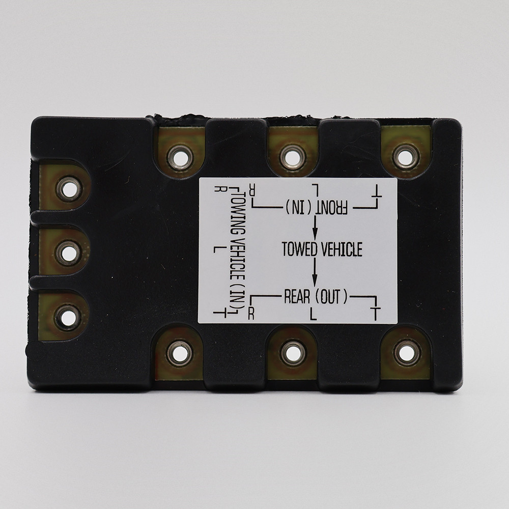
The kit includes: one 26 ft. 4-wire harness (294-0562), one 9-terminal diode block (294-0560), one 14 gauge tinned wire splitter (294-0563), one 16-14 gauge insulated butt connector (294-0250), five 5-inch beaded nylon cable ties (290-0297), and nine #6-32 x 1/2 wire piercing washer screws (201-0462).
If your towing vehicle is already wired for towing, you need a mating plug. If not pre-wired, you need a pigtail and self-stripping wire tap connectors. If your vehicle has separate amber turn signals and red brake lights, you need a tail light converter (not included). A heavy duty flasher unit may also be required in the towing vehicle to handle the added circuit load.
Automatic Equipment recommends installation by a trained professional due to the risk of incorrect wiring causing blown fuses, damaged wiring or computer systems, fire, or bodily injury. Automatic Equipment will not be responsible for personal property damage or bodily injury caused by incorrect wiring or misuse of the product.
Starting in the engine compartment, run the harness through the firewall, under the driver's side door sill plate, under the back seat, and into the trunk area. The wire at the front of the engine compartment should be wired into either a 4-wire or 6-wire trailer plug mounted to the front of the towed vehicle, depending on your motorhome setup.
No. Do not pre-strip wires. Start the wire piercing screws into the tail light connector first, then place the wires under their respective screws and tighten down. If the wire is light gauge and the piercing screws do not penetrate the wire casing properly, double the wire under the screw to make a good connection.
Use a 12 Volt D.C. continuity lamp tester with a needle point prod. Ground one end of the tester and insert the prod through the insulation of each wire to identify hot wires. Vehicle lights must be on and the corresponding turn signals must be operating for wires to be hot. When tapping into wires under the dash, select wires extending to the rear lights, not those extending to the front lights.
After identifying and marking the brake and turn signal wires, shut off power and cut each wire. Place the wires from the front under their respective screws and tighten down. Do not over-tighten. Place the wires to the back lights of the towed vehicle under their respective screws and tighten down. Do the same with wires from the 26 ft. 4-conductor cable. If the wire is light gauge, double the wire under the screw to ensure proper penetration and connection.
The white wire must be grounded to the vehicle chassis. It is also important to have a good ground on the towing vehicle. Proper grounding is critical for correct operation and is one of the first things to check if lights do not work properly after installation.
For Type B vehicles where the brake light wire splits before the lights: cut the main brake wire coming from the front and strip it back approximately 1/4 inch. Use the butt connector provided to connect the stripped wire and the single wire on the splitter, then crimp with a wire terminal crimper. Attach the two ends of the splitter to the left and right screws on the front of the connector. Attach the brake wire going to the back brake lights to the appropriate terminal based on whether it goes to the left or right brake light first.
For Type C vehicles where one brake light wire comes from the other brake light socket: cut the wire connecting the first brake light to the second brake light. Connect the wire that goes to the second brake light to the appropriate terminal on the diode block, which will correspond with the side the second light is on. The jumper wire between the left and right brake lights must be removed.
Check what type of existing socket the towing vehicle has and purchase a mating plug. Use a 12 volt lamp tester to identify each pin in the socket, then connect the 4-wire cable according to the wiring diagram color scheme for your vehicle type.
A pigtail will need to be purchased and wired into the existing wiring of the towing vehicle. Connect the white wire from the pigtail to a suitable ground. To connect the other three wires from the pigtail to the existing towing vehicle wiring, use a 12 volt D.C. continuity lamp to identify the appropriate hot wires at the rear of the towing vehicle. Vehicle lights and turn signals must be activated for current to travel through the wires. Ensure sufficient length to reach the plug on the towed vehicle.
Use the same procedure to identify the brake light wire with a 12 volt D.C. continuity lamp. A tail light converter (not included) is needed to convert the amber/red 4-wire system to the standard red only 3-wire system. A heavy duty flasher unit may also be required in the towing vehicle to power the added circuit load of the towed vehicle.
Plug the towed vehicle's pigtail into the towing vehicle's socket and turn on the towing vehicle's lights. Test each turn signal and the brake lights. If lights do not work properly, there must be a loose connection or a wiring error. Recheck all connections, especially the ground connections. Before towing, test the entire system to ensure proper operation.
On some vehicles with separate amber turn signals, the third brake light or back window light may blink with one of the turn signals while in towing mode only. This is caused by the wiring configuration and can be prevented by following the optional wiring instructions for the third brake light provided in the manual.
While applying power to the brake lights, use a 12 Volt D.C. continuity tester to locate the hot wire feeding power to the positive side of the third brake light. Cut this wire, leaving 6-12 inches extending from the positive side for splicing. Cover the other exposed end with electrical tape. Obtain a piece of 16 gauge stranded wire long enough to reach from the 9-screw diode block to the hot wire. Splice one end to the wire extending from the positive side of the third brake light using a butt connector. Place the other end under either the L or R wire piercing screw on the front side of the diode block, on the opposite side of the screw from the existing wire. Test the entire system before towing.
No. When placing multiple wires under a wire piercing screw, place them on opposite sides of the screw rather than stacking them on top of each other. This ensures proper connection and prevents poor electrical contact.
The manual does not specify the wire gauge of the 26 ft. harness (part 294-0562). Contact the manufacturer or your local supply center for this specification.
The wire splitter (part 294-0563) is 14 gauge tinned wire.
Use 16 gauge stranded wire, which is available at most automotive stores. This wire connects from the 9-screw diode block to the hot wire extending from the positive side of the third brake light.
The 9-terminal diode block (part 294-0560) manages the signal routing between the towing and towed vehicles' lighting systems. It must be wired into the system at the correct point relative to where the existing brake wires split to prevent both turn signals from flashing together or other wiring errors.
Yes. Under normal use, the diode block will become warm to the touch. This is not a cause for alarm.
Incorrect wiring may result in blown fuses, damaged wiring or computer systems, fire, or bodily injury. Automatic Equipment recommends installation by a trained professional and will not be responsible for any personal property damage or bodily injury caused by incorrect wiring or misuse of this product.
After wiring the towed vehicle, check to make sure the vehicle's tail, brake, and turn signal lights operate the same as they did prior to installation of the tail light connector and 4-conductor cable. Plug the towed vehicle's pigtail into the towing vehicle's socket, turn on the towing vehicle's lights, and test each turn signal and the brake lights. If lights do not work properly, recheck all connections, especially the ground connections.
The BX8811 works with motorhomes and tow vehicles connecting to towed vehicles. It supports Type A (standard red turn signals), Type B (separate amber signals with brake wire split before lights), and Type C (separate amber signals with brake power from other socket) systems. If your vehicle has separate amber and red signals, you also need a tail light converter (not included).
Wire terminal crimper, wire stripper, small wire cutter, standard screwdriver, electrical tape, and a 12 Volt D.C. continuity tester with needle point prod. You must also purchase a mating plug or pigtail separately depending on your towing vehicle setup.
Yes. Automatic Equipment recommends installation by a trained professional due to the risk of incorrect wiring causing blown fuses, damaged wiring, computer damage, fire, or bodily injury.
No. Do not pre-strip wires. Start the wire piercing screws into the connector first, then place wires under their respective screws and tighten down. Do not over-tighten.
Use a 12 Volt D.C. continuity lamp tester with needle point prod. Ground one end and insert the prod through wire insulation to identify hot wires. Vehicle lights must be on and turn signals operating. Select wires extending to rear lights, not front lights.
The white wire must be grounded to the vehicle chassis, and a good ground must be established on the towing vehicle. Poor grounding is a common cause of lights not working properly.
Possible causes include: (A) bad, loose, or faulty ground on either or both vehicles; (B) short circuit in the system on either or both vehicles; (C) motorhome alternator too small; (D) motorhome wiring too light to handle extra power requirements; (E) motorhome may require a heavy duty flasher unit to handle the extra load; (F) adding an additional ground between both vehicles may help.
Possible causes include: (A) feedback is present caused by a bad ground or short; (B) motorhome has a weak battery—replace or start motorhome and try again; (C) there could be a bad or shorted bulb on the towed vehicle.
Possible causes include: (A) the diode block is wired into the system before the existing brake wires split—move the block to a point after the existing brake wires are separate; (B) for Type C vehicles, the jumper wire between the left and right brake lights must be removed.
Possible causes include: (A) bad diode block; (B) the diode block is wired in after the existing wires split, therefore both wires from the back of the car must be connected separately to the diode block.
On some vehicles with separate amber turn signals, the third brake light or back window light may blink with one of the turn signals while in towing mode. Follow the optional wiring instructions for the third brake light provided in the manual to prevent this. After completing those steps, the third brake light will not function when in towing mode but will function normally when driving the vehicle.
No reviews have been added for this product.