
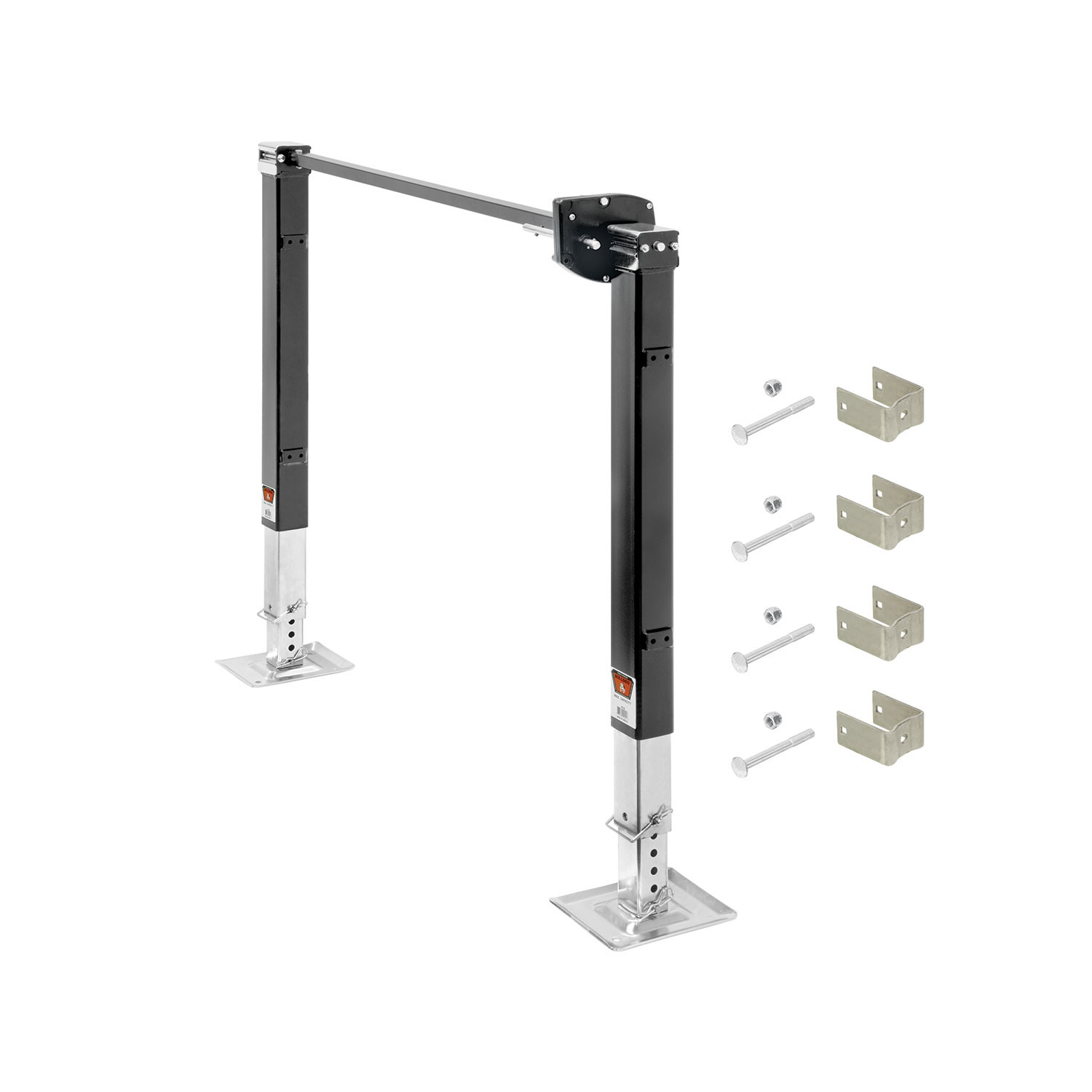
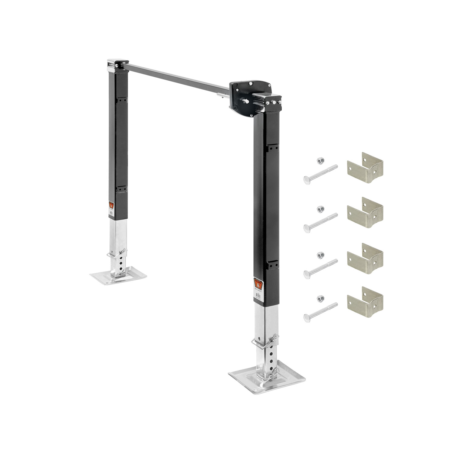
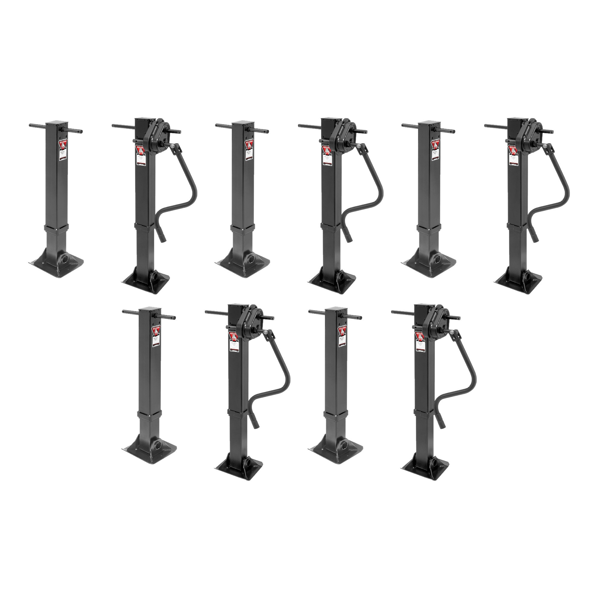
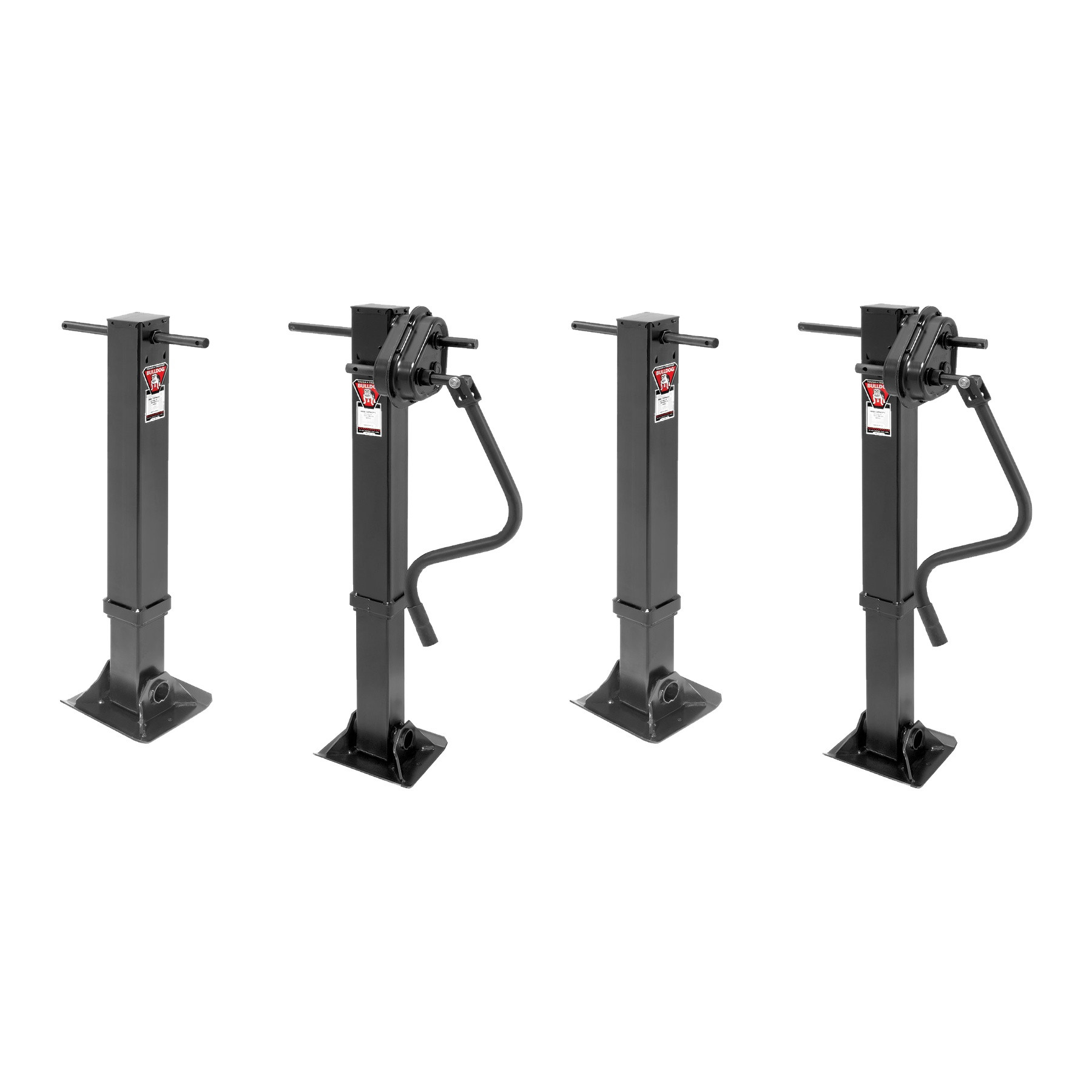
Bulldog Fifth Wheel Landing Gear, 45,000 lbs. Lift Capacity, 17 in. TravelBulldogOriginal price was $1,225.00. Current price is $823.04.Out of Stock
View productOur in-house experts typically reply within one business day.

Bulldog


Always the correct part
We know our products
Quality Products
Free Shipping!
Always the correct part
We know our products
Quality Products
Free Shipping!

| BRAND: | BULLDOG |
| PART NUMBER: | 500162 |
| WARRANTY: | LIMITED 5 YEAR WARRANTY |
| WEIGHT: | 72 LBS |
| CAPACITY: | 8,000 LBS. |

Founded in 1920, Bulldog has become the standard for heavy-duty trailer connection hardware in agricultural, military and utility service. The line covers gooseneck hitches and couplers, A-frame and channel-mount trailer couplers with the Wedge-Latch mechanism, and heavy-duty jacks, built for unmatched strength, reliability and safety under demanding loads.
Bulldog was founded in 1920 and has spent more than a century supplying the connection hardware that heavy trailers depend on. Its market has always been the demanding end: agricultural, military and utility applications where a coupler failure is not an inconvenience but a serious incident. The brand summarises its position as Tough and Tested, and it sits within the Horizon Global towing group alongside Reese, Draw-Tite, Fulton, Tekonsha, Bargman and Wesbar.
Gooseneck equipment is the brand's signature. Gooseneck hitches mount in the truck bed over the rear axle, which places the load where the chassis can carry it properly and allows far tighter turning than a receiver hitch permits. Matching gooseneck couplers attach at the trailer end, in round tube and square configurations across the capacity range used by livestock, equipment and flatbed trailers.
The conventional trailer coupler range is built around the Wedge-Latch mechanism, which uses a wedge to take up wear between coupler and ball rather than relying on a fixed clamp that loosens over time. That matters on a trailer accumulating hard miles, where slack in the coupling shows up as noise and shock loading. Couplers are offered in A-frame form for standard tongues and in channel-mount form for straight tongue and fabricated frames, with adjustable channel versions that let a coupler be positioned to suit the tongue height.
Heavy-duty jacks complete the line, sized for the tongue weights that gooseneck and equipment trailers generate. Across the range the emphasis is consistent: forged and heavy-section components, load ratings backed by testing, and hardware specified for agricultural, military and heavy-duty commercial use rather than occasional recreational towing.
Experts available to answer your questions
Call 888-634-94945 Years
The Bulldog F3644 is available in three configurations: Traditional Landing Gear Configuration (with single motor and cross shaft), Dual Output Powered Drive Landing Gear with High Speed Drive variation, and Dual Output Powered Drive Landing Gear with High Torque Drive variation. Dual motor kits do not include a cross shaft. High Speed and High Torque variations are wired differently and require different wiring schematics.
10 AWG minimum wire gauge is required for all RV landing gear wiring connections, including battery leads, motor leads, and switch connections.
Yes. Disconnect the battery ground cable before installation to avoid accidental shock and/or damage to the electrical system. Reconnect the ground cable after wiring is complete and test both jacks to ensure they travel in the correct EXT (extended) and RET (retracted) directions.
Yes, if the gear is being mounted to the frame using weld brackets. All welding must be performed by a certified AWS welder. Weld brackets are affixed to the frame member using 1/4" fillet welds on both sides, and the jack is then secured to the brackets with supplied carriage bolts and nuts torqued to 25 ft-lbs.
Torque carriage bolts and nuts to 25 ft-lbs when securing the jack to the weld brackets.
Torque pull-pin assembly bolts to 15 ft-lbs when installing pull-pin assemblies to the bottom of the inner tube.
In the event of vehicle power loss or motor malfunction, insert the special Emergency Override Crank bolt (3/4" hex head), which is included with the product, into the open drive hole on the motor and crank the jack manually using a ratchet or similar tool.
The Bulldog RV Landing Gear (model F3644) is an electric or manual landing gear system for RVs. It supports the RV when parked and can be raised or lowered using an electric motor (in powered configurations) or manually via an emergency override crank. The gear is available in Traditional, High Speed Drive, and High Torque Drive configurations.
Traditional Landing Gear Configuration includes a telescoping cross shaft that installs between the jacks. However, dual motor kits do not include a cross shaft.
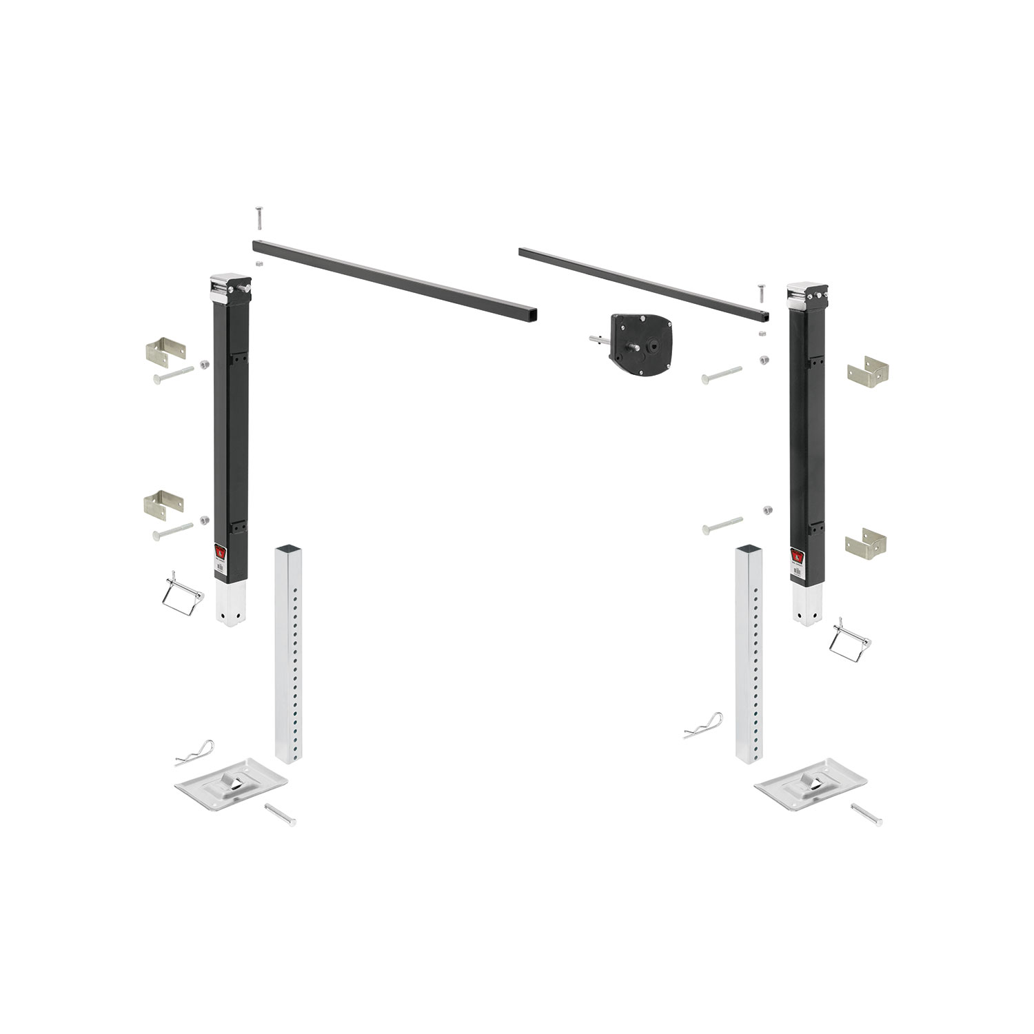
A screw and plastic retainer are supplied to secure the gear reducer box to the jack input shaft. The gear reducer box must be installed onto the jack with the longer input shaft.
Machine screws are supplied with the product to attach the electric gear motor to the reducer box.
Lynch pins are supplied to install foot plates to the jack tube (in Traditional configuration) or to drop tubes (in Dual Output Powered Drive configuration).
The manual specifies that a ratchet or similar tool is needed to operate the emergency override crank bolt (3/4" hex head) in case of motor failure. For welding installation, a certified AWS welder is required. The manual does not specify other general installation tools required.
Position weld brackets to the frame so that the welded tabs on the jack are captured as shown in Figure 1. The weld brackets are then affixed to the frame member using 1/4" fillet welds on both sides.
1. Install the gear reducer box onto the jack with the longer input shaft, using the supplied screw and plastic retainer. 2. Attach the electric gear motor to the reducer box using supplied machine screws. 3. Install the telescoping cross shaft between the jacks. 4. Install pull-pin assemblies (if included) to the bottom of the inner tube and torque bolts to 15 ft-lbs. 5. Install foot plates to the jack tube with supplied lynch pins. 6. Mount the switch and connect wires according to wiring instructions.
The shorter PINK (+) and BLACK (-) leads from the switch connect directly to the battery terminals. The longer RED (+) and BLACK (-) leads from the switch connect to the RED and BLACK motor leads. Connect like color wires together.
The 500168 model uses two switch assemblies, one for each drive motor.
For High Torque Drive: Connect both PINK wire leads from the switch panel directly to the POSITIVE (+) battery terminal. Connect both WHITE wire leads from the switch panel directly to the NEGATIVE (-) battery terminal. Connect the YELLOW wire lead to the BLACK motor lead on the left side jack. Connect the BLUE wire lead to the RED motor lead on the left side jack. Connect the RED wire lead to the BLACK motor lead on the right side jack. Connect the BLACK wire lead to the RED motor lead on the right side jack. All connections require 10 AWG minimum wire gauge.
For High Speed Drive: Connect both PINK wire leads from the switch panel directly to the POSITIVE (+) battery terminal. Connect both WHITE wire leads from the switch panel directly to the NEGATIVE (-) battery terminal. Connect the YELLOW wire lead to the RED motor lead on the left side jack. Connect the BLUE wire lead to the BLACK motor lead on the left side jack. Connect the RED wire lead to the RED motor lead on the right side jack. Connect the BLACK wire lead to the BLACK motor lead on the right side jack. All connections require 10 AWG minimum wire gauge.
Use the attached template for installing the switch and carefully route the wires to avoid the possibility of chafing. Use plastic loom (not included) if necessary to protect wires from abrasion.
Never position any part of your body under or on the path of any portion of the product or the load being supported or moved. Do not allow children to play on or around the product or load. Secure the load, vehicle and trailer from rolling by blocking wheels when operating the jack or coupling the trailer. These jacks are designed for vertical loading only; excessive side forces may cause jack failure and must be avoided. Never attempt to adjust the drop foot or drop leg when there is any load on the jack.
To reset the overload circuit breaker, push in the respective button on the switch assembly.
After reconnecting the battery ground cable, test both jacks to ensure they travel in the correct EXT (extended) and RET (retracted) directions.
Periodically check mounting hardware for proper torque and tighten if necessary. Maintain the electrical system including the battery and charger (not included). Ensure all connections are tight and free of corrosion. Make sure the battery is fully charged prior to use. Do not direct a high pressure spray at the electric motors or switch assemblies. Do not use if parts are worn, bent, broken or if the product has been modified or altered. Always replace bent, broken or worn parts before using the product.
Cequent Trailer Products provides a Limited Five Year Warranty covering material defects in material and workmanship, ordinary wear and tear excepted, provided installation and use is in accordance with product instructions. The warranty is not transferable and applies only to the original consumer purchaser. If the product does not comply with the warranty, the sole remedy is replacement without charge or refund of purchase price at the manufacturer's option. The warranty does not cover normal wear and tear, damage from abuse, neglect, misuse, accident, misapplication, overloading, improper installation (including welds), improper maintenance and repair, or product alteration by anyone other than the manufacturer.
Contact Cequent Trailer Products Customer Service Department at 1-715-693-1700 or 1-800-604-9466. Please specify the product model number. You can also visit www.cequentperformanceproducts.com for additional details. Use only Cequent Trailer Products parts or parts of equal quality for repair.
Use caution during installation to ensure the motor does not receive sharp blows or other stresses due to a drop, tip over, or similar incident.
When using the drop foot or drop leg, make certain the supplied pin is fully inserted through both sides of the inner tube and the drop tube before using the jack.
Refer to the stamped markings or decals on the product to obtain the rated capacity. If uncertain, contact Cequent Trailer Products at 800-604-9466 or www.cequentperformanceproducts.com.
After reconnecting the battery ground cable following installation, test both jacks to ensure they travel in the correct EXT (extended) and RET (retracted) directions. If they do not move in the correct direction, verify that the wiring connections match the appropriate wiring schematic for your configuration (High Speed Drive or High Torque Drive). Ensure all wire connections are tight and free of corrosion. If the problem persists, contact Cequent Trailer Products at 1-800-604-9466.
If the overload circuit breaker trips, push in the respective button to reset it. If the breaker continues to trip repeatedly, this may indicate an electrical fault or motor malfunction. Check all wiring connections for tightness and corrosion. Ensure the battery is fully charged. If the problem persists, contact Cequent Trailer Products at 1-800-604-9466 or 1-715-693-1700.
First, verify that the battery is fully charged and all electrical connections are tight and free of corrosion. Check that the battery ground cable is properly connected. Verify that the wiring matches the correct schematic for your configuration (High Speed Drive or High Torque Drive). If the motor still does not respond, you can manually operate the jack using the Emergency Override Crank bolt (3/4" hex head). Insert the crank bolt into the open drive hole on the motor and crank the jack manually using a ratchet or similar tool. If the motor remains unresponsive, contact Cequent Trailer Products at 1-800-604-9466.
On Sale Today
Original price was $625.00. Current price is $448.50.You save $176.50 (28%)
Free Shipping
Ships free on all orders
 Authorized Dealer
FREE ShippingFREE SHIPPING
Estimated delivery Sun, Sep 27 - Wed, Sep 30
Order before 2 PM EST Monday–Friday for same-day processing
Guaranteed safe & secure checkout
George
Ordered online. Shipment arrived on time and with all the correct parts. Great customer service and friendly staff. Also, pricing was great!
May 22, 2023