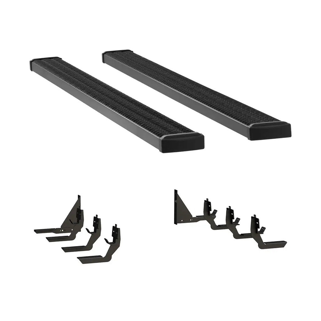
LUVERNE Grip Step 7" x 98" Aluminum Wheel-to-Wheel Running Boards, Select Ram 3500 415098-401338LuverneOriginal price was $923.95. Current price is $810.95.In Stock
View productOur in-house experts typically reply within one business day.

Luverne
Verify Fitment
Select your vehicle to confirm this part fits.


Always the correct part
We know our products
Quality Products
Free Shipping!
Always the correct part
We know our products
Quality Products
Free Shipping!

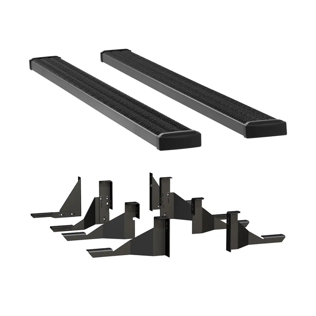
LUVERNE Grip Step wheel-to-wheel running boards equip your pickup truck for whatever job lies ahead. They offer easier truck bed access, fleet-level safety, a highly rust-free construction and a custom fit for your truck and lifestyle. Grip Step wheel-to-wheel steps are the ideal solution for better truck bed access. Whether you need to reach a truck tool box, ladder rack or some cargo in the truck bed, the wheel-to-wheel steps are extra-long, providing a convenient step up for reaching into the truck bed. Grip Step running boards are also built for hard work, featuring expanded metal treads that offer fleet-approved safety. The open treads ensure maximum traction for your boots -- whether rain or shine -- and they also help keep your truck's interior clean by allowing dirt, snow and debris to pass through the boards. For superior resistance to the elements, Grip Step wheel-to-wheel running boards are made from aluminum alloy. They're strong, lightweight and highly corrosion-resistant. To maximize this corrosion resistance, the running boards and brackets are both shielded in a durable black powder coat finish. The running boards also feature hardened plastic end caps that eliminate sharp corners and add a professional touch. All LUVERNE Grip Step wheel-to-wheel steps are designed for vehicle-specific applications. This ensures a custom fit and the easiest possible installation. The running boards mount with vehicle-specific brackets and use pre-existing mounting points to avoid difficult modifications. This particular set of wheel-to-wheel running boards is designed to fit specific years of the Ram 3500 (see application information to verify fitment; brackets included but shipped separately).
Grip Step wheel-to-wheel running boards are designed to be the best running boards for work trucks, featuring a unique expanded metal tread pattern for superior traction and a 7" width for reliable footing.

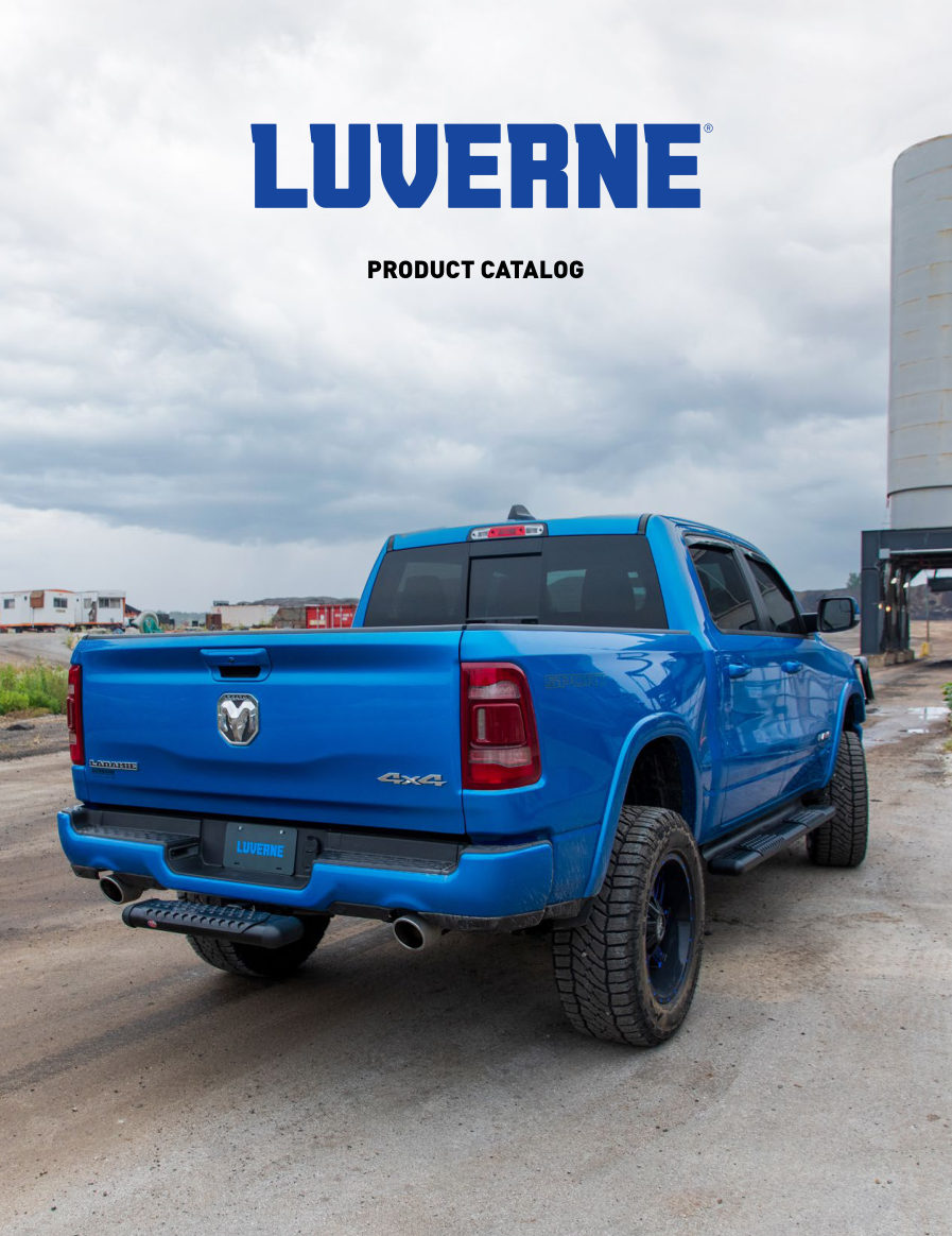
LUVERNE has manufactured truck accessories in the United States since 1963, specialising in grille guards, running boards, side steps and mud guards for pickups, commercial vans and SUVs. Products are built primarily from stainless steel, aluminium and mild steel, with model-specific mounting kits that use existing frame locations for a bolt-on installation.
LUVERNE has been manufacturing automotive accessories in the United States since 1963, and six decades of continuous production have made it a nationally recognised name in the truck accessory market. Now a Lippert brand, it concentrates on a defined set of products rather than spreading across the whole aftermarket: front-end protection, step access and spray protection for pickup trucks, commercial vans and sport utility vehicles.
Step products are the largest part of the catalog and the range is unusually deep, because the right step depends on the vehicle's ride height, the width of the rocker panel and how often people get in and out. The O-Mega II six-inch oval steps give a wide, flat standing surface in polished stainless or black powder coat, while the Regal 7 seven-inch oval steps go wider still for full-size crew cabs and lifted trucks. The broader running board and side bar range covers round tube, oval and boxed profiles across cab configurations, with treads positioned at the door openings where they are used.
Grille guards protect the front end against impacts, brush and road debris, built in tubular stainless or steel with model-specific brackets that tie into factory frame mounting points. Because the fit is engineered per vehicle, installation is a bolt-on job that does not require drilling or cutting on most applications.
Rounding out the line, LUVERNE mud guards and mud flaps shield rocker panels, paint and following vehicles from stones and road spray, in widths matched to the tyre and fender they sit behind. Material choice runs through everything the brand does: stainless steel where appearance and corrosion resistance matter most, aluminium where weight is the priority, and mild steel with protective coating where strength and value lead. Customers include contractors, fleet operators, van upfitters and truck owners.
Experts available to answer your questions
Call 888-634-9494Limited Lifetime Warranty (Five-Year Finish, One-Year Parts)
1 compatible vehicles
| Year | Make & Model | Style | Bed | Notes |
|---|---|---|---|---|
| 2013 - 2019 | Ram 3500 | Standard Cab Pickup | 8'2" Bed | — |
The LUVERNE Grip Step 7" x 98" Aluminum Wheel-to-Wheel Running Boards, Select Ram 3500 415098-401339 (Part #FTNF415098-401339) fits 2013-2019 Ram 3500 models. The 2019 model year is the last year covered by this part number. For newer models, check for an updated version.
Yes, the LUVERNE Grip Step 7" x 98" Aluminum Wheel-to-Wheel Running Boards, Select Ram 3500 415098-401339 (Part #FTNF415098-401339) is designed to fit the 2013-2019 Ram 3500.
The LUVERNE Grip Step 7" x 98" Aluminum Wheel-to-Wheel Running Boards, Select Ram 3500 415098-401339 (Part #FTNF415098-401339) is designed for 8'2" bed trucks. Check the fitment chart for your specific Ram 3500 configuration.
The LUVERNE Grip Step 7" x 98" Aluminum Wheel-to-Wheel Running Boards, Select Ram 3500 415098-401339 (Part #FTNF415098-401339) fits the following vehicles: 2013-2019 Ram 3500. Always verify your specific year, make, and model before ordering.
The LUVERNE Grip Step 7" x 98" Aluminum Wheel-to-Wheel Running Boards, Select Ram 3500 415098-401339 (Part #FTNF415098-401339) Refer to the included instructions for installation details. Basic hand tools are typically all you need.
The Model 415114 Grip Steps package includes: 2 aluminum extrusions (part 551388), 10 upper support braces (part 551296), 4 end caps (part 551394), 14 lower spacer plates (part 551298), 20 carriage bolts 5/16-18 x 1" (part 108683), 20 flat washers 5/16" (part 101369), 20 serrated flange nuts 5/16-18 (part 102680), and 8 self-drilling tek screws #8 x 1/2" (part 107958). The specific bracket package for your vehicle is ordered separately and includes additional fasteners.
Model 415114 Grip Steps are listed as universal applications, but they require a vehicle-specific bracket package to mount. The board itself can be cut to fit many applications, but you must order the correct bracket package for your vehicle. The brackets are what determine fitment to your specific vehicle.
The Model 571339/401339 W2W Mega/Grip Step Brackets are designed for 2013-2015 RAM 3500 Pickups in all cab styles: Regular Cab, Quad Cab, Crew Cab, and Mega Cab. The rear bracket orientation differs between Regular/Quad/Crew Cab and Mega Cab models, so refer to the appropriate figure during installation.
Yes. For Regular Cab pickups only, the front and rear cab mounting brackets are used. The center mounting bracket and its fasteners may be discarded and do not need to be installed.
To cut the board to length, you will need a saber saw, chop saw, or hack saw. You will also need a screwdriver or power drill for the self-drilling tek screws, and a wrench or socket set to tighten the carriage bolts and nuts. Flat black paint is recommended to touch up the cut ends of the board.
You will need a wrench or socket set to remove and install the factory body mount bolts and to tighten all fasteners. A torque wrench is required to tighten fasteners to the specified 19 lb-ft. You may need a jack or lift to access the leaf spring shackle bolts during installation.
Yes. The board can be modified from its original length to fit many applications. Determine the length you need and cut it using a saber saw, chop saw, or hack saw. After cutting, use flat black paint to touch up the cut ends.
No drilling is required. The brackets mount to existing factory body mount holes and leaf spring shackle mounting points on the vehicle. However, you must remove the factory body mount bolts, which will not be reused.
1. Slide the appropriate number of support braces (item #2) into the channel of the step board (item #1). 2. Slide the end cap (item #3) over the front and rear of each step. 3. Using the supplied #8 x 1/2" self-drilling tek screw (item #8), screw the end cap to the bottom of the step. 4. Set the step on the mounting brackets and slide each support brace over the top of each mounting bracket. 5. Attach the flat spacer plate (item #4) between the support brace and the top of the mounting bracket. 6. Attach using the 5/16-18 x 1" carriage bolt, washer, and flange nut (items #5, 6, 7). 7. Tighten all fasteners to 19 lb-ft.
Slide the end cap (item #3) over the front and rear of each step. Using the supplied #8 x 1/2" self-drilling tek screw (item #8), screw the end cap to the bottom of the step. The self-drilling screw will create its own hole.
1. Assemble the load reaction studs with hardware as specified (steps 2.1-2.2). 2. Attach the load reaction stud assemblies to the mounting brackets (step 3). 3. Remove factory front, center, and rear body mount bolts on the right side (one side at a time). 4. Install the front, center, and rear mounting brackets to the body mounts using the specified bolts and washers, leaving fasteners finger tight (steps 4.1-4.3). 5. Attach the rear outboard bracket to the rear inboard bracket (step 4.4). 6. Attach the upper mounting bracket to the leaf spring shackle (step 5.1). 7. Fasten the lower bracket to the upper bracket (step 5.2). 8. Attach the step plate per its instructions. 9. Position the load reaction stud assembly and tighten all fasteners to 19 lb-ft (step 7).
On the short threaded end of the stud, install a 3/8" serrated flange nut (item #16) backwards to the bottom of the thread. Then install a 3/8" flat washer (item #15) and rubber cushion washer (item #14) tight against the serrated flange nut. The end of the stud must be recessed in the rubber washer approximately 3/16 inch. On the long threaded end of the stud, install a 3/8" serrated flange nut (item #16) backwards to near the bottom of the threads. Use a 4" stud (item #18) for the front bracket and a 3" stud (item #17) for the rear brackets.
Remove the factory front, center, and rear body mount bolts on the right side (one side at a time); these will not be reused. For the front bracket, use an M12-110mm bolt (item #11) and 2.0" washer (item #13), leaving fasteners finger tight. For the center bracket, use an M12-110mm bolt (item #11) and 2.0" washer (item #13), leaving fasteners finger tight. For the rear bracket, use an M12-116mm bolt (item #12) and 1/2" flat washer (item #20), leaving fasteners finger tight. Rear bracket orientation differs between Regular/Quad/Crew Cab and Mega Cab models.
Attach the rear outboard mounting bracket (item #7 or #8) to the rear inboard mounting bracket (item #5 or #6) in the upper mounting location using three 3/8-16 x 1.0" screws (item #19), 3/8" flat washers (item #15), and 3/8" flange nuts (item #16).
Loosen the bolt that fastens the leaf spring to the vehicle. Slide the upper mounting bracket (item #9) between the bolt head and the frame bracket. Place a 3/8" bolt and washer (items #15, #19) through the hole in the upper mounting bracket and frame bracket, then fasten with a 3/8" serrated flange nut (item #16). Tighten the leaf spring bolt, making sure the upper mounting bracket is level. Fasten the lower bracket (item #10) to the upper bracket using a 3/8" bolt, washer, and flange nut (items #15, #16, #19) in the two lower holes of the upper bracket, ensuring it sits level to the front brackets.
All fasteners on the Model 415114 Grip Steps must be torqued to 19 lb-ft. This includes the 5/16-18 x 1" carriage bolts, washers, and flange nuts that attach the step assembly to the mounting brackets.
The 3/8" serrated flange nuts on either side of the load reaction stud bracket must be torqued to 19 lb-ft. This is the final tightening step after positioning the load reaction stud assembly so the rubber cushion is snug against the side of the frame.
The front bracket is attached using an M12-110mm bolt (item #11) with a 2.0" washer (item #13). These fasteners are left finger tight during initial installation and are not final-tightened until step 7.
The rear bracket is attached using an M12-116mm bolt (item #12) with a 1/2" flat washer (item #20). These fasteners are left finger tight during initial installation and are not final-tightened until step 7.
The center bracket is attached using an M12-110mm bolt (item #11) with a 2.0" washer (item #13). These fasteners are left finger tight during initial installation and are not final-tightened until step 7.
Three 3/8-16 x 1.0" screws (item #19), 3/8" flat washers (item #15), and 3/8" flange nuts (item #16) are used to attach the rear outboard bracket to the rear inboard bracket in the upper mounting location.
A 3/8" bolt (item #19) and washer (item #15) are placed through the hole in the upper mounting bracket and frame bracket, then fastened with a 3/8" serrated flange nut (item #16).
A 3/8" bolt (item #19), washer (item #15), and flange nut (item #16) are used in each of the two lower holes of the upper bracket to attach the lower bracket.
Yes. During initial installation (steps 4-5), all fasteners are left finger tight. The final tightening to 19 lb-ft occurs only after the load reaction stud assembly is positioned so the rubber cushion is snug against the side of the frame (step 7).
The rubber cushion washer (item #14) provides vibration isolation and load distribution between the stud assembly and the vehicle frame. It must be recessed approximately 3/16 inch into the stud and positioned snug against the side of the frame during final installation.
The manual states that rear bracket orientation differs between Regular/Quad/Crew Cab and Mega Cab pickups but does not explain the reason. You must refer to Figure 1 for Regular/Quad/Crew Cab installation and Figure 2 for Mega Cab installation to ensure correct orientation.
After installation, verify that all fasteners are tightened to 19 lb-ft and that the step is securely attached to the mounting brackets. Ensure the step plate is in the correct position and that all support braces are properly seated over the mounting brackets.
After installation, verify that all fasteners are tightened to 19 lb-ft. Ensure the load reaction stud assembly rubber cushion is snug against the side of the frame. Check that the upper mounting bracket at the leaf spring shackle is level and that the lower bracket sits level to the front brackets.
Model 415114 is universal, but requires a vehicle-specific bracket package. Order the correct bracket package for your vehicle; the board can be cut to fit many applications.
Yes, if your vehicle is a 2013-2015 RAM 3500 Pickup in any cab style (Regular, Quad, Crew, or Mega Cab). Rear bracket orientation differs between cab types.
No drilling is required for the step assembly itself. The board can be cut to length using a saber saw, chop saw, or hack saw. Mounting depends on the vehicle-specific bracket package.
No drilling is required. Brackets mount to existing factory body mount holes and leaf spring shackle points. Factory body mount bolts must be removed and discarded.
Saber saw, chop saw, or hack saw to cut the board; screwdriver or power drill for tek screws; wrench or socket set for bolts and nuts; torque wrench to tighten to 19 lb-ft; flat black paint for cut ends.
Wrench or socket set to remove factory bolts and install fasteners; torque wrench to tighten to 19 lb-ft; possibly a jack or lift to access leaf spring shackle bolts.
All fasteners must be torqued to 19 lb-ft.
The manual does not specify whether the brackets must be removed. Follow the instructions included with your specific bracket package.
Fasteners are left finger tight during initial installation (steps 4-5) and final-tightened to 19 lb-ft only after the load reaction stud assembly is positioned with the rubber cushion snug against the frame (step 7).
Ensure you are using the supplied #8 x 1/2" self-drilling tek screw (item #8) to attach the end cap to the bottom of the step. The self-drilling screw will create its own hole. If the screw is not holding, verify that the end cap is fully seated over the step before driving the screw.
Verify that all fasteners have been torqued to 19 lb-ft using a torque wrench. Check that the support braces are properly seated over the mounting brackets and that the flat spacer plate is correctly positioned between the support brace and the mounting bracket. Re-tighten all fasteners to 19 lb-ft if necessary.
After sliding the upper mounting bracket between the bolt head and frame bracket and installing the fastener, tighten the leaf spring bolt while monitoring the bracket position. The manual specifies that you must tighten the leaf spring bolt making sure the upper mounting bracket is level. Adjust the bracket position as needed before final tightening.
The lower bracket (item #10) must sit level to the front brackets. Verify that the upper bracket (item #9) is level at the leaf spring shackle (step 5.1). Then attach the lower bracket using the two lower holes of the upper bracket with a 3/8" bolt, washer, and flange nut (items #15, #16, #19), ensuring it sits level to the front brackets before final tightening.
Position the load reaction stud assembly so that the rubber cushion washer is snug against the side of the frame. Then tighten the 3/8" flange nuts on either side of the bracket to 19 lb-ft. If the cushion does not seat properly, verify that the stud is inserted from the inboard (frame) side through the lowest hole in the bent flange of the bracket that will allow the rubber washer to seat firmly.
On Sale Today
Original price was $972.95. Current price is $853.95.You save $119.00 (12%)
Free Shipping
Ships free on all orders
 Authorized Dealer


Quick Ship
In stock and ready to ship — order now!
FREE ShippingFREE SHIPPING
Estimated delivery Sat, Oct 10 - Tue, Oct 13
Order before 2 PM EST Monday–Friday for same-day processing
Guaranteed safe & secure checkout
No reviews have been added for this product.