Ask a Question About This Product
Our in-house experts typically reply within one business day.
Our in-house experts typically reply within one business day.

CURT
Verify Fitment
Select your vehicle to confirm this part fits.











Always the correct part
We know our products
Quality Products
Free Shipping!
Always the correct part
We know our products
Quality Products
Free Shipping!

CURT offers a variety of high-quality trailer hitches and accessories for select vehicle models. Find the perfect fit for your towing needs at TowUniverse.
CURT, a Lippert brand, offers a complete line of towing products and is the leading manufacturer of custom-fit trailer hitches. We offer the broadest selection of custom-fit hitches, and each one is designed, welded, and coated in Wisconsin.
CURT is also a leader in flat towing products, as well as 5th wheel, gooseneck, and weight distribution hitches, ball mounts, electrical components, cargo solutions, and other towing accessories.
For everything from passenger cars and vans to full-size pickups and SUVs, CURT is 'The First Name in Towing Products®.'
Experts available to answer your questions
Call 888-634-94941 compatible vehicles
| Year | Make & Model | Notes |
|---|---|---|
| 2023 - 2025 | Ford Escape | PHEV |
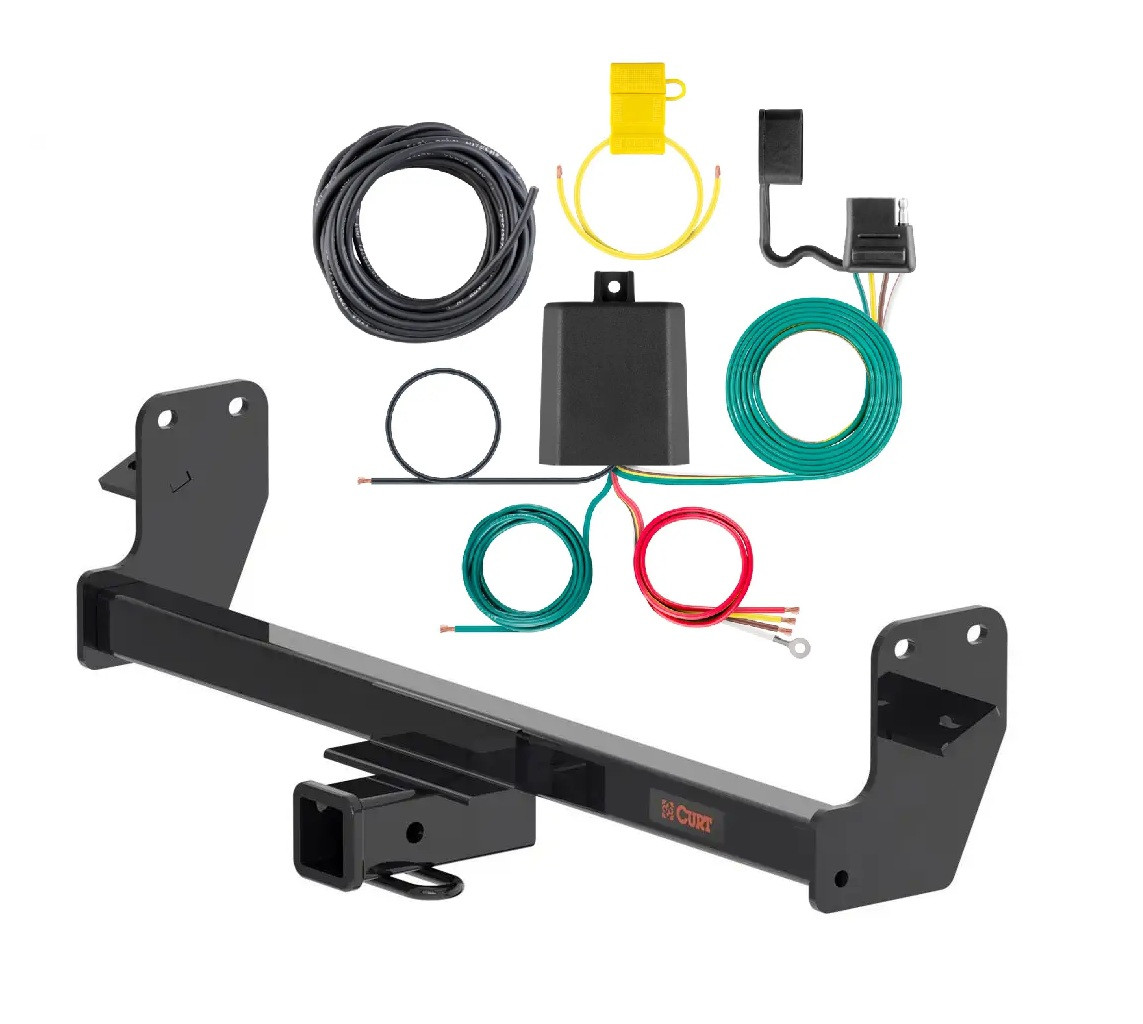
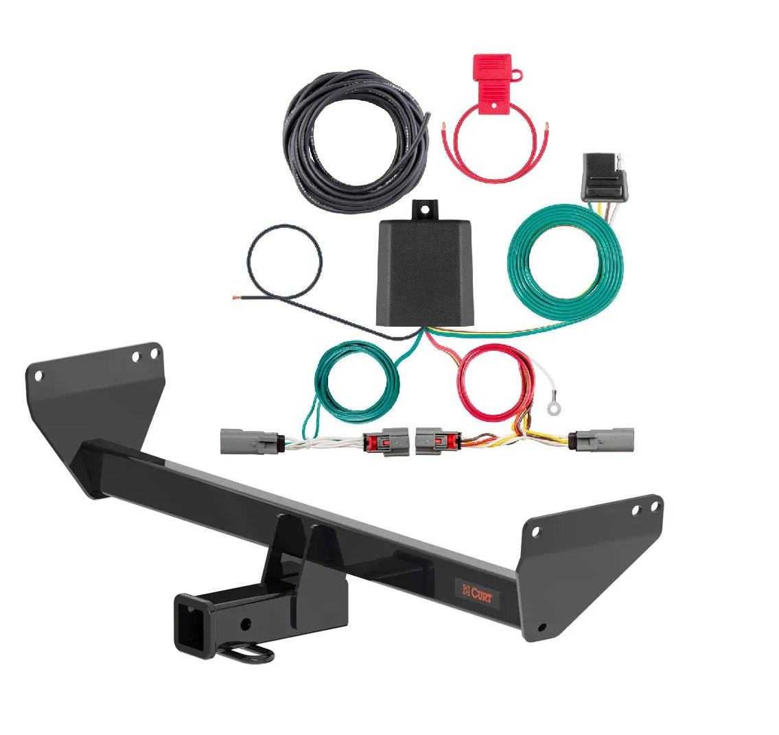
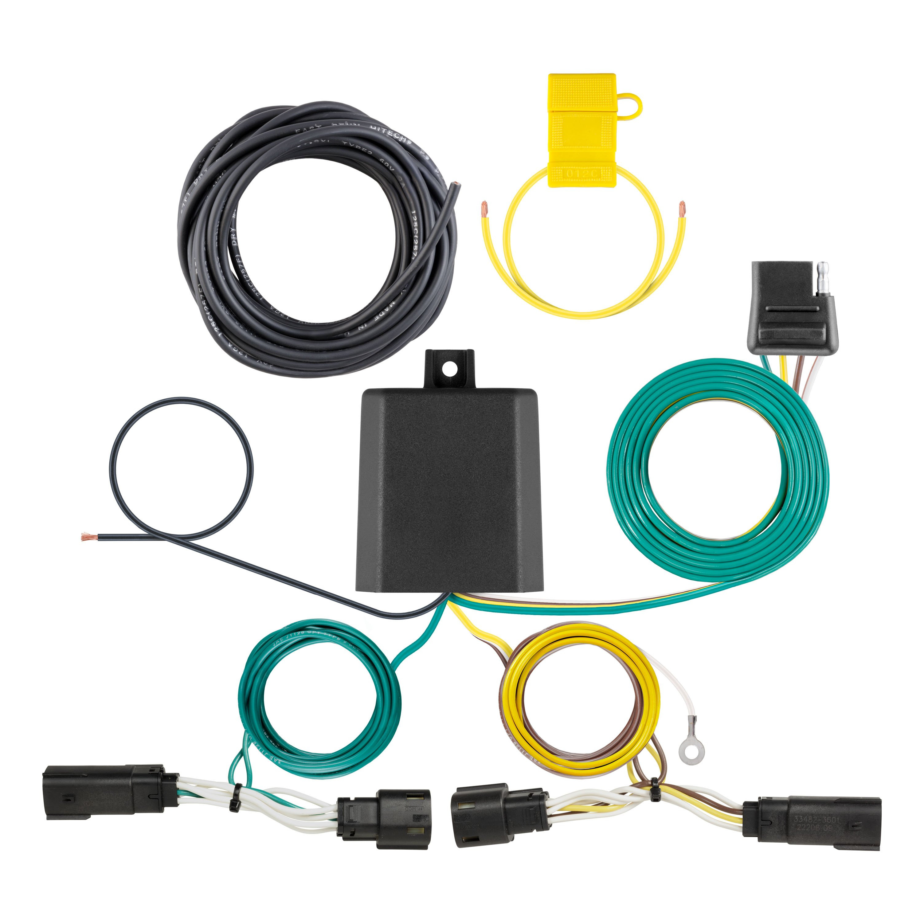
Part 56507 is a wiring converter system for SUVs and vans that integrates trailer lighting functions. It includes a powered converter module, custom harnesses with colour-coded wires (yellow for left turn, green for right turn, red for brake, brown for taillight), a black converter box, ground wire with ring terminal, cable ties, double-sided tape, a 4-flat dust cover, and a ground screw. The system converts vehicle lighting signals to trailer-compatible outputs.
Part 56507 is designed for SUVs and vans. The manual does not specify which makes, models or model years are compatible. Contact Curt Manufacturing or consult a fitment database with your vehicle's year, make and model to confirm compatibility before purchasing.
Yes. The converter system is designed only for 12-volt negative ground systems. Do not use it on positive ground or 24-volt systems.
Required tools are: ratchet, 7mm socket, socket extension, Torx T-25 bit, small flathead screwdriver, wire crimper, wire stripper, cutting tool, panel trim removal tool, electrical tape, grommet sealant, and cable ties (provided). Proper tools will improve installation quality and reduce time required.
The kit includes: custom harnesses with colour-coded wires (yellow, green, red, brown), black converter box, white ground wire with ring terminal, provided ground screw, double-sided tape for mounting the converter box, cable ties, 4-flat dust cover, and a fuse holder with 15-amp max fuse. The fuse must be installed only after all other installation steps are complete.
Yes. Disconnect the negative battery terminal in the engine compartment on the driver side before beginning installation. Fasten this wire down and away from the battery while completing the installation. Reconnect it only after all other steps are complete and before testing the system.
The installation difficulty is rated as Moderate. This rating is based on time and effort involved and may vary depending on installer expertise, vehicle condition, and availability of proper tools and equipment.
The manual identifies ten wiring locations (S1–S10) for SUVs and vans: S1 behind driver side taillight housing, S2 behind passenger side taillight housing, S3 behind driver side rear access panel, S4 behind passenger side rear access panel, S5 behind driver side rear bumper, S6 behind center of rear bumper, S7 behind passenger side rear bumper, S8 under rear floor panel, S9 behind driver side rear access panel, and S10 behind passenger side rear access panel. Part 56507 uses locations S3 and S4.
Installation follows eight steps: (1) disconnect negative battery terminal and secure it away from battery; (2) open rear hatch, remove cargo tie-down trim covers and Torx T-25 tie-downs on both sides, remove floorboard to expose spare tire; (3) use 7mm socket to remove threshold fasteners on hatch threshold on both sides, remove threshold with trim tool; (4) remove spare tire foam tie-downs on both sides using trim tool, relocate ECU between tire and threshold; (5) loosen driver-side wall panels, locate driver-side taillight housing, separate connectors carefully, install custom harness with yellow wire between factory harness and taillight; (6) mount black converter box inside vehicle near taillight using double-sided tape, secure white ground wire to vehicle frame using provided screw or 3/32" drilled hole; (7) route green wire harness to passenger side, repeat step 5 with green wire, secure with cable ties; (8) route black power wire from battery per the Powered Converter Lead Instruction Sheet, verify function with test light or trailer, reconnect battery, install 4-flat dust cover, reinstall all removed items.
Open the rear hatch. Use a small flathead screwdriver to remove the cargo tie-down trim covers. Use a Torx T-25 tool to remove the tie-downs on both sides of the vehicle. This exposes the floorboard and spare tire.
Use a 7mm socket to remove the threshold fasteners on the hatch threshold between the side of the vehicle and the cargo tie-down mount on both sides. Use a trim tool to remove the threshold itself.
Use a trim tool to remove the spare tire foam tie-downs. Starting on the driver side, locate the tie-downs and pry up softly to loosen them from the threaded bolt tie-down. Repeat on the passenger side. After removing the foam, remove the ECU from the foam and place it between the tire and the threshold to provide clearance for the passenger-side interior panel to be moved.
Use a trim tool on the driver side to loosen the side wall panels of the vehicle. Locate the driver-side taillight housing. Separate the connectors, taking care not to damage the locking tabs. Install the custom harness with the yellow wire in-between the factory harness and taillight.
Locate a flat spot inside the vehicle near the taillight. Adhere the black converter box using the provided double-sided tape. Before mounting, ensure the area is clean and free of rust, dirt and paint.
Locate a suitable grounding point near the converter box connector, such as an existing screw with nut in the vehicle frame. If no suitable point exists, drill a 3/32" pilot hole for the provided ground screw. The area must be free of rust, dirt and paint. Secure the white ground wire with the ring terminal on the existing fastener or with the provided ground screw. Before drilling, check for miscellaneous items that may be hidden behind or under any surface to avoid damage and personal injury.
Locate the harness end with the green wire and route it along the back of the vehicle over to the passenger side. Repeat the driver-side installation procedure (Step 5) using the green wire. Secure the green wire using the provided cable ties as needed.
Route the black 12 GA power wire from the vehicle battery as shown on the provided 'Powered Converter Lead Instruction Sheet' on page 5 of this manual. Route the wire carefully to avoid any pinch points and hot or rotating components. When passing the power wire through sheet metal, use an existing grommet, add a grommet, or use silicone to protect the power wire from sharp edges. Secure the power wire to the vehicle chassis using the provided cable ties.
Once the 12-volt power wire is connected to the harness, verify that the harness is functioning by attaching the battery and testing with a test light, 4-flat tester, or a functioning trailer. When in use, route the 4-flat with the center of the vehicle and out of the hatch to the trailer, staying clear of the hatch's latching mechanism. When not in use, roll up and store in a convenient, out-of-the-way location. Secure any loose wires with provided cable ties. Reinstall all items removed during installation. If the negative battery terminal was disconnected at the beginning, reconnect it. Install the provided 4-flat dust cover to help prevent corrosion.
Drilling may be required only for the ground wire connection. If no suitable existing screw with nut is available in the vehicle frame near the converter box, drill a 3/32" pilot hole for the provided ground screw. Before drilling, check for miscellaneous items that may be hidden behind or under any surface to avoid damage and personal injury.
Drill a 3/32" pilot hole for the provided ground screw if an existing fastener is not available. The area must be free of rust, dirt and paint before drilling.
Signal circuits are rated at 3.0 amps per side. Tail/running circuits are rated at 6.0 amps total. Do not exceed the product rating or the tow vehicle lamp load rating, whichever is lower. The battery connection must be fuse-protected with a 15-amp max fuse. Exceeding the product rating can cause loss of warranty, overheating and potential fire.
Use a 15-amp maximum fuse. The fuse holder is provided with the kit. Install the fuse only after all other installation steps are complete. Do not exceed 15 amps, as exceeding the product rating can cause loss of warranty, overheating and potential fire.
Use 12 GA wire or larger for the black power wire routed from the vehicle battery to the converter system.
The custom harness includes four colour-coded wires: yellow for left turn signal, green for right turn signal, red for brake, and brown for taillight. These wires connect the vehicle's lighting circuits to the trailer connector.
Route the black 12 GA power wire to the positive (+) battery terminal using a ring terminal connector. The battery connection must be fuse-protected with a 15-amp max fuse (install fuse after all other steps are complete). Disconnect the negative battery terminal before wiring the power wire. When passing the power wire through sheet metal, use an existing grommet, add a grommet, or use silicone to protect the wire from sharp edges.
The white ground wire with ring terminal provides the ground connection for the converter system. Secure it to the vehicle body using an existing screw with nut in the vehicle frame, or drill a 3/32" hole and use the provided ground screw. The mounting area must be free of rust, dirt and paint.
Follow these safety precautions: (1) Do not lay tools across the positive battery terminal (typically marked with red covers or a red '+' symbol) to avoid shorts, sparks and electrical shock. (2) Disconnect the negative battery terminal before beginning installation and secure it away from the battery. (3) Before drilling, check for miscellaneous items that may be hidden behind or under any surface to avoid damage and personal injury. (4) When routing the power wire, avoid pinch points and hot or rotating components. (5) Do not exceed the product rating or tow vehicle lamp load rating. (6) Do not exceed 15 amps on the fuse, as this can cause loss of warranty, overheating and potential fire.
When in use, route the 4-flat connector with the center of the vehicle and out of the hatch to the trailer, staying clear of the hatch's latching mechanism. When not in use, roll up and store in a convenient, out-of-the-way location.
Once the 12-volt power wire is connected to the harness, verify that the harness is functioning by attaching the battery and testing with a test light, 4-flat tester, or a functioning trailer. This confirms that all signal circuits (left turn, right turn, brake, taillight) are operating correctly before using the system.
Periodic inspection of all wires and connections should be performed to ensure there is no visible damage or loose connections. Check the system regularly, especially before towing, to maintain safe operation.
Yes. Install the provided 4-flat dust cover to help prevent corrosion of the connector when the system is not in use.
Do not lay tools across the positive battery terminal (red covers or '+' symbol) to avoid shorts, sparks and electrical shock. Do not exceed 15 amps on the fuse to prevent fire risk.
Gross trailer weight (GTW) is 2,000 lbs. and tongue weight (TW) is 200 lbs. Never exceed your vehicle manufacturer's recommended towing capacity.
Required tools: ratchet, torque wrench, 3/4" socket, 10mm socket, 11mm socket, 6" socket extension, paint marker, die grinder, and 1/2" fishwire (qty. 4 included). A tools reference guide is available at curtmfg.com/trailer-hitch-installation.
Yes. The exhaust must be lowered during installation. Use an 11mm socket to remove the hose clip from the passenger side exhaust hanger stud, then remove the exhaust hanger bolts on both sides using a 10mm socket. Place jack stands or supports under the exhaust to prevent damage. The exhaust is reinstalled in Step 7.
Yes. The vehicle mounting holes must be enlarged using a die grinder. The hitch is temporarily positioned to align the rearmost mounting holes, then the forwardmost mounting holes are marked and enlarged with a die grinder.
All 1/2" hardware must be torqued to 110 ft-lb using a 3/4" socket.
Yes. The EVAP canister heat shield must be temporarily removed. Using a 10mm socket, remove the three fasteners on the driver side, remove the heat shield, and set it aside. The three 10mm nuts for the EVAP canister mounting bracket should be loosened (not removed) for additional clearance. The heat shield is reinstalled in Step 7.
The kit includes 4 carriage bolts (1/2"-13 x 1-1/4", grade 8), 4 serrated-flange nuts (1/2"-13), 4 square-hole spacers (1/4" x 1" x 2-1/2"), and 4 pieces of 1/2" fishwire.
The installation difficulty is rated as Easy. However, installation difficulty levels are based on time and effort involved and may vary depending on installer expertise, vehicle condition, and availability of proper tools and equipment.
The fishwire technique is used to guide the carriage bolts and spacers through the vehicle frame rails during mounting. The coiled end of the fishwire is inserted through the hitch mounting hole and out the access hole, passed through the spacer, and threaded into the bolt. The wire is kinked to keep the spacer separate from the bolt, then pulled to guide the hardware through the frame and out the mounting hole. This prevents loss of bolts or spacers inside the frame rail.
In Step 4, fishwire the 1" x 2-1/2" spacers and 1/2" carriage bolts through the enlarged hole and out the rearmost mounting hole on both sides. Then reverse fishwire the spacers and bolts in and out the enlarged forwardmost hole on both sides of the vehicle. The fishwire technique prevents bolts and spacers from being lost inside the frame rail.
After fishwiring the spacers and bolts in Step 4, raise the hitch into position in Step 5 and secure it using 1/2" flange nuts. Then torque all 1/2" hardware to 110 ft-lb using a 3/4" socket in Step 6.
In Step 3, temporarily raise the hitch into position, aligning the rearmost mounting holes of the hitch with the mounting holes in the vehicle frame. Use a paint marker to mark the location of the forwardmost mounting holes. Lower the hitch and enlarge the marked holes using a die grinder.
If contact occurs between the hitch and the exhaust heat shield, use a suitable pry tool to gently reshape the heat shield away from the hitch. Alternatively, as noted in Step 7, you may bend the trim of the EVAP canister heat shield to prevent contact with the hitch if necessary.
In Step 7, secure the EVAP canister that was loosened in Step 2 and reinstall the heat shield using the three 10mm bolts. Raise the exhaust into position and reinstall the bolts securing the exhaust hangers and hose clip that were removed in Step 1. Bend the trim of the EVAP canister heat shield if necessary to prevent contact with the hitch.
Safety glasses must be worn at all times during installation. When lowering the exhaust, place jack stands or other supports under the exhaust to prevent damage to the vehicle. Never exceed your vehicle manufacturer's recommended towing capacity when using the hitch.
Periodic inspection of the trailer hitch should be performed to ensure all mounting hardware remains tight and structural components are secure. To help prevent damage to the product or vehicle, refer to the specified torque specifications (110 ft-lb for all 1/2" hardware) when securing hardware.
Visit www.curtmfg.com for a full-color copy of the instruction manual, helpful videos, guides, and more. For product support, call 877.287.8634. For a tools reference guide, visit curtmfg.com/trailer-hitch-installation. For towing safety information, visit curtmfg.com/understanding-towing. To register your purchase or access warranty information, visit warranty.curtgroup.com/surveys.
On Sale Today
Original price was $543.90. Current price is $384.98.You save $158.92 (29%)
Free Shipping
Ships free on all orders
 Authorized Dealer
Quick Ship
In stock and ready to ship — order now!
FREE ShippingFREE SHIPPING
Estimated delivery Thu, Oct 22 - Sun, Oct 25
Order before 2 PM EST Monday–Friday for same-day processing
Guaranteed safe & secure checkout
No reviews have been added for this product.