Ask a Question About This Product
Our in-house experts typically reply within one business day.
Our in-house experts typically reply within one business day.

WARN
Verify Fitment
Select your vehicle to confirm this part fits.
2024 - 2025 Can-Am Maverick R
Confirmed to Fit

Always the correct part
We know our products
Quality Products
Free Shipping!
Always the correct part
We know our products
Quality Products
Free Shipping!
Legendary WARN Quality
Color: Black
When your job calls for a reliable, versatile plow system, look no further than Warn Industries for durability and maximum performance. WARN plows feature integrated design elements that make your work easier.

WARN Industries has built off-road recovery equipment since 1948, beginning with locking wheel hubs and expanding into the electric winch that made the brand a standard. The lineup covers truck, Jeep and SUV winches, powersports winches, industrial and hydraulic hoists, bumpers, mounting systems and rigging gear, manufactured in Clackamas, Oregon.
Arthur and Sadie Warn founded WARN Industries in 1948 with an idea for converting surplus World War II Jeeps into practical road vehicles. Arthur's locking wheel hub was the product that did it, and it went on to reshape the four-wheel-drive market. By 1954 WARN hubs were offered as factory optional equipment by major domestic automakers, and over the following decades the company supplied hubs as original equipment to Chrysler, Ford, GM, Kia, Nissan and others.
The defining moment came in 1959 with the electric winch. Before it, a vehicle-mounted winch ran off a power take-off and needed the engine turning to work. An electric winch could pull even with the vehicle stalled on a hill, which changed what recovery meant for four-wheelers, racers and ranchers. The M8274 arrived in 1974 and remains in the line. Today's truck, Jeep and SUV winches include the VR EVO, ZEON and ZEON Platinum families.
As the ATV market grew through the 1980s, WARN introduced the first purpose-built powersports winch and created a category. The current ATV and UTV winch range includes the VRX and AXON lines, the latter using a combined motor and contactor unit that cuts installation time substantially. Vehicle-specific winch mounts, bumpers and plow systems complete the fitment.
On the work side, WARN builds electric and hydraulic industrial winches and hoists for towing, utility, military and severe-duty applications, from the compact Drill Winch through 30,000 pound Series XL units and the modular Series G2. Recovery is supported by a full rigging range of straps, shackles, snatch blocks and dampers.
The company operates 180,000 square feet of manufacturing, engineering and office space in Clackamas, Oregon, employs close to 400 people, holds more than 100 patents and produces over 600 products under ISO 9001, ISO 14001 and IATF 16949 certified systems.
Experts available to answer your questions
Call 888-634-94941 compatible vehicles
| Year | Make & Model | Notes |
|---|---|---|
| 2024 - 2025 | Can-Am Maverick R | — |
The Warn 110957 Snow Plow Mount Can Am Maverick R Black Steel (Part #BCSQ110957) fits the following vehicles: 2024-2025 Can-Am Maverick R. Always verify your specific year, make, and model before ordering.
Yes, the Warn 110957 Snow Plow Mount Can Am Maverick R Black Steel (Part #BCSQ110957) is designed to fit the 2024-2025 Can-Am Maverick R.
The Warn 110957 Snow Plow Mount Can Am Maverick R Black Steel (Part #BCSQ110957) fits 2024-2025 Can-Am Maverick R models. The 2025 model year is the last year covered by this part number. For newer models, check for an updated version.
The Warn 110957 Snow Plow Mount Can Am Maverick R Black Steel (Part #BCSQ110957) Refer to the included instructions for installation details. Basic hand tools are typically all you need.
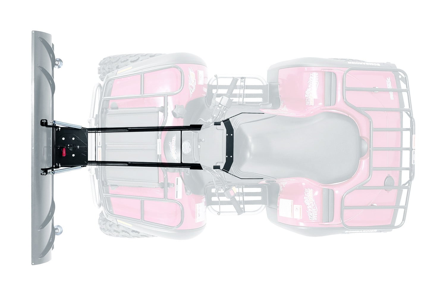
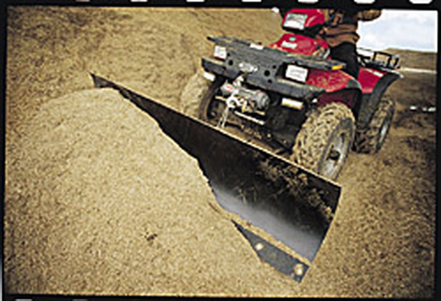
The WARN Plow System is a snow and material removal tool that attaches to powersports vehicles. It consists of a curved moldboard blade that scrapes material from the ground surface and rolls it to the side of the vehicle. The system is divided into four separate kits: Plow Blade, Push Tube Base Assembly, Vehicle Plow Mount, and Plow Lift or Winch. You must have one of each kit to have a working plow system.
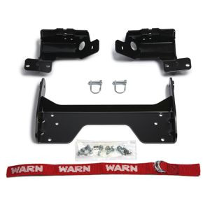
The Vehicle Plow Mount kit is designed specific to each vehicle. You must select the correct mount kit for your vehicle model. The manual does not provide a fitment chart or list of compatible vehicles. Contact your local WARN dealer or visit www.warn.com to determine the correct mount kit for your specific vehicle.
The system has four main components: (1) Plow Blade—the primary cutting component with a curved moldboard designed to roll snow or plowed material; (2) Push Tube Base Assembly—the main frame that transfers the vehicle's pushing power to the blade and allows side-to-side pivoting; (3) Vehicle Plow Mount—vehicle-specific brackets that attach the plow to your vehicle; and (4) Plow Lift or Winch—the lifting device that raises and lowers the blade.
The wear bar is a rectangular metal bar bolted to the bottom of the plow blade. It is the cutting edge that contacts the ground and takes the brunt of the force and wear during plowing. It is a wear item and should be replaced when worn back to the adjacent moldboard edge. The steel wear bar provides about ¾ inch (19 mm) of wear material before requiring replacement. Some blades have a reversible bar that can be flipped once to double its life before total replacement is needed.
Plow skids are wear items that control the cutting or plowing height of the blade. They are designed to hold the blade wear bar off the ground at a user-selected height. They should be inspected often and replaced as needed. Skids can be set to raise the wear bar the maximum distance off the surface to remove only the top layer of material, or adjusted lower for deeper cutting. Operating with skids at maximum position is optimal when grading material onto the surface or when trying to keep the wear bar from damaging the surface.
The Plow Blade Return Spring restrains the plow blade in an upright position during plowing. If the blade wear bar contacts a very low non-movable object, the blade will roll over (forward) against the force of this spring. This trip mechanism protects the plow and vehicle from damage. Never remove the springs or hard-fixture the blade to the plow base or vehicle, as doing so will prevent the plow from tripping during an impact and may damage the plow, vehicle, or eject the rider from the vehicle.
The plow and vehicle must be on a flat, level surface. The vehicle engine should be off, transmission should be in park, and the parking brake should be set. The front wheels should be straight and the plow blade pivot angle should be set to the straight position before installing the plow. Inspect the plow mount for any debris, damage, and ensure fasteners are properly torqued before installing or using the plow.
1. Put on gloves and inspect equipment for loose hardware, worn components, and damage. Set blade pivot to straight position. 2. Position the blade assembly and vehicle on flat level ground about 3 feet apart. Slowly move the vehicle towards the mounting tabs until the push tube is between the front tires. 3. Lift the push tube at the mounting tab end and slide the plow assembly onto the wear bar, seating the alignment pilot disks into the mount cradle. 4. Install the connecting pins on each side (you may need to wiggle the push tube to allow easy insertion; a tapered drift may help align holes). Latch the pin bail. 5. Attach the lift device (winch or plow lift) by routing the rope through the rope guide and attaching the hook to the cross member of the tube assembly. 6. Check lift device operation by lifting and lowering the plow to note how far you can lift without stalling or causing impact. 7. Set the blade attack angle, skid height, and blade pivot angle for your job conditions.
Put the winch in freespool and pull out 3 to 5 feet (1 to 2 meters) of wire rope. Route the rope through the rope guide and attach the hook to the hook eye (cross member of the tube assembly). Close the rope guide and insert the locking pin. Always ensure the hook latch is completely closed. Never remove the hook from the end of the winch rope, as it prevents the rope from being pulled into the roller fairlead and protects your fingers and extremities from being pulled in.
Torque fasteners to the following specifications: M8 Bolts—18 ft-lb (25 N.m); M10 Bolts—37 ft-lb (50 N.m). Fasteners must be torqued periodically to ensure they remain tight. Always tighten all nuts and bolts securely per the installation instructions.
The blade attack angle is adjusted by a socket head capscrew and has three positions to match plowing conditions. To adjust: remove the socket head capscrew from the middle position on each side, rotate the blade to the desired position, align the holes, insert the bolt in the desired position, and torque to the recommended specification. The most aggressive attack angle (top of blade tipped forward) is recommended for sand and gravel and produces better scraping on ice or hardpack snow. The middle setting provides good all-around performance for heavy or wet snow. The least aggressive angle (blade tipped back) is recommended for deep snow as it allows the wear bar to slide under the snow and produce the most blade down force.
Spring tension is adjusted by shifting the spring eye bolts forward or backward. Shifting the eye bolt forward will soften the spring setting, which lowers the blade rollover force and should be used with lighter vehicles and typically the most aggressive (forward) blade attack angle. Shifting the eye bolt backward will stiffen the spring, producing the highest blade rollover force, useful for gravel driveway maintenance or plowing ice and snow clean. To adjust: loosen the nuts securing the eye bolt to the plow assembly (push down on the spring to relieve pressure on the eye bolt), shift the eye bolt forward or backward to your desired position, then tighten the nuts to the recommended torque. Be sure to keep tension between the two springs equal.
Inspect the plow mount for debris such as rocks, dirt, and branches that can become lodged while operating the vehicle without the plow. Check for any damage and ensure all fasteners are properly torqued. Inspect the plow retaining pins and the bail that secures them to the mount. The bail can become damaged with use, so check that it locks firmly to the mount. If needed, remove the pin and bend the bail wire to ensure it fits tightly to the mount.
Never exceed 5 MPH (8 km/h) with the plow installed, even with the blade up. Keep your speed low and pay attention to how the machine is responding to your control. Use low range and 4WD if the vehicle is equipped. Driving at speeds that cause the plow to bounce while in the up position may cause the lift system to back-drive, lowering the plow down and potentially causing it to impact a stationary object.
Never operate the vehicle on side slopes greater than 10° with the plow installed. Never plow side hills steeper than 10 degrees. Vehicle weight balance and stability can be greatly changed when a plow is attached and when the vehicle is pushing a loaded plow, affecting steering and vehicle control.
Never operate this product if you are under 16 years of age. Never operate this product when under the influence of drugs, alcohol, or medications. Always wear a helmet and appropriate clothing when operating the vehicle. Always use appropriate personal protection equipment when servicing, installing, or using the product.
Before plowing: (1) Put on gloves and inspect your equipment for loose hardware, worn components, and damage. Correct issues before you plow. (2) Set blade pivot to straight position. (3) Inspect the plow mechanism, fasteners, cable, and adjustments. Replace all worn or damaged parts before operating. (4) Check the winch for back-driving and rope nesting. Failure to do so may cause the plow to creep downward when in the up position. (5) Check lift mechanism, straps, or winch rope integrity. (6) Ensure the T-handle pivot latch is fully engaged before plowing. (7) Inspect winch rope, hook, and slings. Frayed, kinked, or damaged rope must be replaced immediately. (8) Plan your route and ensure bystanders are aware and stay clear. (9) Suit up with proper safety equipment including helmet and appropriate clothing.
The moldboard surface has a nonstick material coating from the factory, but like all nonstick surfaces, this coating will wear out over time. The moldboard surface will become scratched with use. It is recommended to apply wax or a nonstick spray to the moldboard surface periodically before plowing. This will prevent the snow from sticking to the blade and provide the best material roll.
The blade hinge bushings will require lubrication periodically for the best plow performance. Spray a light lubricating oil on both sides of the center blade ribs just above the large hinge bolt. This lubrication should run down the rib and into the bushing area. For better results, the blade retaining M16 nuts and retaining washers should be removed to allow lubrication to be applied directly to the bushing.
The blade pivot bushing is located in the center of the plow base. Remove the plow from the vehicle and place the blade face down so that the plow base and bushing are vertical. Spray a light lubricating oil around the base retaining plate and then rotate the tube assembly a few times to either side. Repeat this a few times to allow the oil to enter the pivot bushing area. The base retaining plate may need to be removed for cleaning and thorough lubrication if the pivot assembly does not turn smoothly.
Always clean off your plow by spraying with fresh water before storage. This will minimize corrosion from road salts or other chemicals. Once the plow is clean, it should be removed from the vehicle. Spray pivots and bushings with light lubricating oil and place in a storage area that is clean and dry. Always repair and lubricate prior to storage, making the plow ready for your next use. Always store the plow system in a dry place when not in use.
Available accessories include: (1) Plastic Wear Bar—an ultra high molecular weight plastic bar that replaces the steel bar, prevents wear, and minimizes scraping on concrete or brick surfaces; (2) Blade Side Wall—heavy duty steel construction that controls runoff of material and prevents material from escaping; (3) Snow Control Flap—a flexible rubber flap that bolts to the top of the blade to keep snow from flowing over the blade; (4) Plow Lift Rope—a durable synthetic rope that replaces the winch rope and stands up to repeated sharp angle pulls; (5) Roller Fairlead for Plow Lifting—designed for Warn winches with a large bottom roller that reduces rope wear; (6) Power-Pivot—an electric device that replaces the pivot latching system and rotates the blade with a button push; and (7) Plow Markers—flexible markers two feet high that mark the corners of the blade to improve visibility when plowing in deep snow. Contact your local dealer or visit www.warn.com to purchase accessories.
Both are lifting devices, but they work differently. If a winch is used, it is recommended that you replace the winch rope with the plow lift rope and replace the standard winch roller fairlead with the plow roller fairlead to reduce rope wear. Using a winch to raise and lower a plow will cause rope wear. The Plow Lift is another method for lifting the plow. This device is specifically designed to lift the plow blade and does not use a rope. The plow lift has internal parts that prevent it from extending due to plow weight. It also contains internal switches that automatically stop the device when fully extended or retracted.
For best plow performance, the plow platform and base must be parallel to the surface being plowed. The vehicle height should be adjusted prior to plowing to set the plow in the correct position. This can be done by adjusting the vehicle spring settings, adjusting tire pressure, and adding or removing weight from the vehicle. Be sure to include the weight of the driver on the vehicle when setting up the machine.
After attachment, plan your route and work scope. Make sure you know what is under the material you are plowing and avoid impacting hidden objects. Be sure bystanders are aware of your activities and stay clear. It is usually best to plow the outer edge of the area to be cleared. To plow a driveway, start by plowing the shoulder first, moving the material to either side of the driveway. This clears the shoulder and allows material in the center to be thrown onto the shoulder or over the material removed from the shoulder. Then suit up to operate your vehicle, following all warnings and wearing the right safety equipment.
Work smartly and keep under control. Plowing changes how a vehicle handles (steering, stopping, and stability), so plow with care and do not rush. If the material is deep, plow several thin layers at a relaxed attack angle, minimizing load on the plow and vehicle. Finish the job with an aggressive attack angle to leave a clean surface. Set your plow up for the conditions—best performance is obtained with the right attack angle, spring tension, and pivot angle. Too much cutting action will slow or stop your progress; too little may not get the job done. When done with your job, park the vehicle on flat level ground and set the brake (put in park) prior to removing the plow.
Always be sure the T-handle pivot latch is fully engaged before plowing. In some instances it may be necessary to push down on the handle to engage it into the plow base. Failure to properly engage the plow may result in loss of vehicle control, which can lead to vehicle damage, personal injury, or even death.
Never raise the plow to a solid (stall/lock) position against the vehicle, as it may damage the vehicle lift device and plow. Do not over-lift the plow during use. Note how far you can lift without stalling the lifting device or causing impact between the plow assembly and the vehicle.
The Vehicle Plow Mount kit is designed specific to each vehicle. Contact your local WARN dealer or visit www.warn.com to determine the correct mount kit for your vehicle model.
The manual does not mention drilling as part of the installation process. The plow attaches using existing vehicle mounting points and connecting pins.
Never exceed 5 MPH (8 km/h) with the plow installed, even with the blade up. Use low range if your vehicle is equipped.
M8 Bolts: 18 ft-lb (25 N.m). M10 Bolts: 37 ft-lb (50 N.m). Torque fasteners periodically to ensure they remain tight.
Inspect the plow before each use. Check for loose hardware, worn components, and damage. Inspect the blade wear bar, skids, fasteners, cable, and adjustments. Replace all worn or damaged parts before operating.
Always wear a helmet and appropriate clothing when operating the vehicle. Always use appropriate personal protection equipment when servicing, installing, or using the product. Always wear gloves when handling winch rope.
Check the winch for back-driving and rope nesting before plowing. Failure to do so may cause the plow to creep downward when in the up position. If the plow creeps down low enough, the blade may hit a stationary object, ejecting the rider from the vehicle and causing serious injury or death. If back-driving or nesting is present, consult the WARN Basic Guide to Winching Techniques for corrective procedures.
Check the lift mechanism, straps, or winch rope integrity. Failure to do so may cause the plow to drop suddenly from the up position and impact a low-lying object, potentially ejecting the rider from the vehicle and causing serious injury or death. Inspect the winch rope, hook, and slings before operating. Frayed, kinked, or damaged winch rope must be replaced immediately. Damaged components must be replaced before operation.
Check the moldboard surface. The nonstick coating will wear out over time. Apply wax or a nonstick spray to the moldboard surface periodically to produce the best material roll. Also verify that the blade attack angle and spring tension are set correctly for your conditions. If the material is too deep or the vehicle has no traction, the plow will not be effective as the material will not be able to roll over in front of the blade. Plow several thin layers at a relaxed attack angle, minimizing load on the plow and vehicle.
The blade pivot bushing is located in the center of the plow base. Remove the plow from the vehicle and place the blade face down so that the plow base and bushing are vertical. Spray a light lubricating oil around the base retaining plate and then rotate the tube assembly a few times to either side. Repeat this a few times to allow the oil to enter the pivot bushing area. The base retaining plate may need to be removed for cleaning and thorough lubrication if the pivot assembly does not turn smoothly.
When installing the connecting pins, you may need to wiggle the push tube assembly to allow the pin to easily insert. If you find difficulty, a tapered drift may help align the holes. Ensure the plow and vehicle are on a flat, level surface and that the plow blade pivot angle is set to the straight position before installing the plow.
Always be sure the T-handle pivot latch is fully engaged before plowing. In some instances it may be necessary to push down on the handle to engage it into the plow base. The handle is spring-loaded so it will automatically engage when the base assembly slots align. Failure to properly engage the plow may result in loss of vehicle control, which can lead to vehicle damage, personal injury, or even death.
The plow retaining pins are secured to the mount by a bail. This bail can become damaged with use. Inspect the bail to make sure that it locks firmly to the mount. Remove the pin and bend the bail wire as needed to ensure that it fits tightly to the mount.
Free Shipping
Ships free on all orders
 Authorized Dealer
Quick Ship
In stock and ready to ship — order now!
FREE ShippingFREE SHIPPING
Estimated delivery Thu, Oct 22 - Sun, Oct 25
Order before 2 PM EST Monday–Friday for same-day processing
Guaranteed safe & secure checkout


Total for 4 items:
$1,602.35
No reviews have been added for this product.