03-08 Mazda 6 Hatchback CURT 4-flat Plug and Play Trailer WiringCURTOriginal price was $92.90. Current price is $87.76.In Stock
View productOur in-house experts typically reply within one business day.

CURT
On Sale Today
Original price was $92.90. Current price is $87.76.You save $5.14 (6%)
Free Shipping
Ships free on all orders
 Authorized Dealer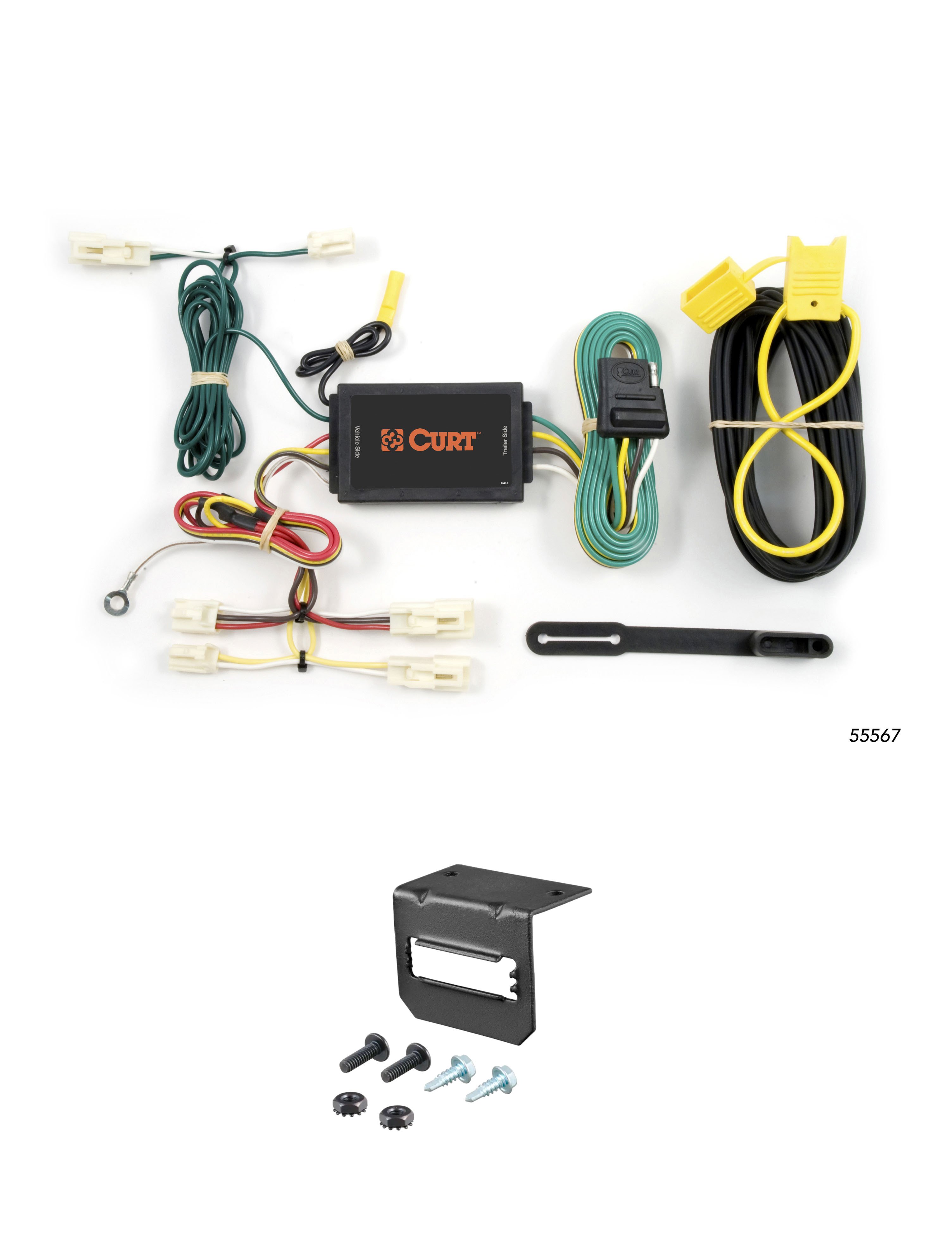



Always the correct part
We know our products
Quality Products
Free Shipping!
Always the correct part
We know our products
Quality Products
Free Shipping!
Verify Fitment
Select your vehicle to confirm this part fits.
Quick Ship
In stock and ready to ship — order now!
FREE ShippingFREE SHIPPING
Estimated delivery Sat, Sep 26 - Tue, Sep 29
Order before 2 PM EST Monday–Friday for same-day processing
Guaranteed safe & secure checkout
| Battery-Powered | Yes |
| Converter Type | Circuit Protected and Powered |
| Electrical System Type | 3W |
| Finish | N/A |
| Material | Blank |
| Mount Type Description | Blank |
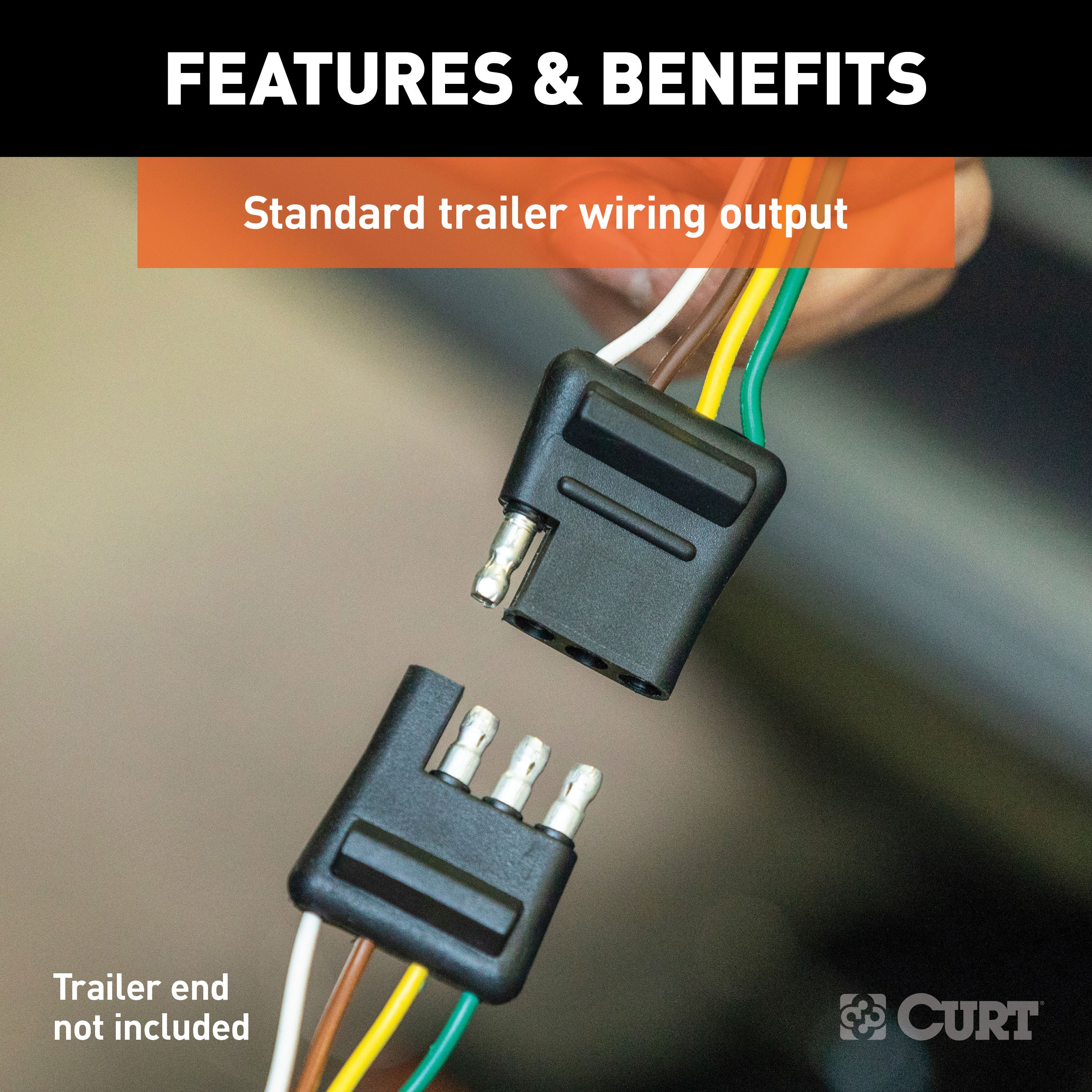
| Output Type | 4-Way Flat |
| Side Application Type Description | Blank |
| T-Connector Location | P3,P4 |
| Tail Light Circuits | 6.0 Amps |
| Turn and Brake Circuits | 3.0 Amps |
| Warranty | One-Year Limited Warranty |

CURT offers a variety of high-quality trailer hitches and accessories for select vehicle models. Find the perfect fit for your towing needs at TowUniverse.
CURT, a Lippert brand, offers a complete line of towing products and is the leading manufacturer of custom-fit trailer hitches. We offer the broadest selection of custom-fit hitches, and each one is designed, welded, and coated in Wisconsin.
CURT is also a leader in flat towing products, as well as 5th wheel, gooseneck, and weight distribution hitches, ball mounts, electrical components, cargo solutions, and other towing accessories.
For everything from passenger cars and vans to full-size pickups and SUVs, CURT is 'The First Name in Towing Products®.'
Experts available to answer your questions
Call 888-634-9494The 03-08 Mazda 6 Sedan CURT 4-flat Plug and Play Trailer Wiring (Part #CTW1772) fits 2003-2008 Mazda 6 models. The 2008 model year is the last year covered by this part number. For newer models, check for an updated version.
Yes, the 03-08 Mazda 6 Sedan CURT 4-flat Plug and Play Trailer Wiring (Part #CTW1772) is designed to fit the 2003-2008 Mazda 6.
The 03-08 Mazda 6 Sedan CURT 4-flat Plug and Play Trailer Wiring (Part #CTW1772) fits the following vehicles: 2003-2008 Mazda 6. Always verify your specific year, make, and model before ordering.
The 03-08 Mazda 6 Sedan CURT 4-flat Plug and Play Trailer Wiring (Part #CTW1772) Refer to the included instructions for installation details. Basic hand tools are typically all you need.
Yes, the Curt 55567 is designed for Mazda 3 vehicles. Installation involves accessing the vehicle wiring harness connectors inside the rear cargo area by removing the plastic scuff panel and pulling back the felt trunk liner. The custom harness connectors are inserted into the vehicle's taillight wiring connectors located behind the taillight housing.
Yes, the Curt 55567 is designed for Mazda 6 vehicles. Installation requires removing the plastic scuff panel and felt trunk liner to access the vehicle wiring harness connectors. On the driver side, you must use a 10mm socket to remove two nuts on the back of the taillight housing and gently pull the housing rearward to access the connectors.
Yes, the Curt 55567 is designed for both hybrid and non-hybrid Toyota Camry models. Installation involves removing the rear scuff panel and felt trunk liner to access the vehicle wiring harness connectors. You must also remove the plastic nuts securing the cargo tray and remove the tray to locate the taillight wiring harness connectors.
Yes, the Curt 55567 is designed for Toyota Corolla vehicles. Installation involves removing the rear scuff panel and felt trunk liner to access the vehicle wiring harness connectors inside the rear cargo area. The connectors are located behind the taillight housing.
Yes, the Curt 55567 is designed for Toyota FJ Cruiser vehicles. Installation is more involved than other applications and requires removing the jack storage compartment door, rear scuff panel, trim panels, and cargo clips to access the vehicle wiring. If your FJ Cruiser is equipped with an optional subwoofer unit, additional removal steps are required before accessing the wiring harness connectors.
The Curt 55567 fits Mazda 3, Mazda 6, Toyota Camry (including hybrid), Toyota Corolla, and Toyota FJ Cruiser.
You will need: ratchet, 8mm socket, 10mm socket, Phillips screwdriver, flat blade screwdriver, and panel trim removal tool. The 10mm socket is used to remove taillight housing nuts on Mazda 6 and subwoofer bolts on FJ Cruiser. The trim removal tool is essential for safely removing plastic panels without damage.
Yes. You need a ratchet, 8mm and 10mm sockets, Phillips and flat blade screwdrivers, and a panel trim removal tool. The trim removal tool is essential for safely removing plastic panels.
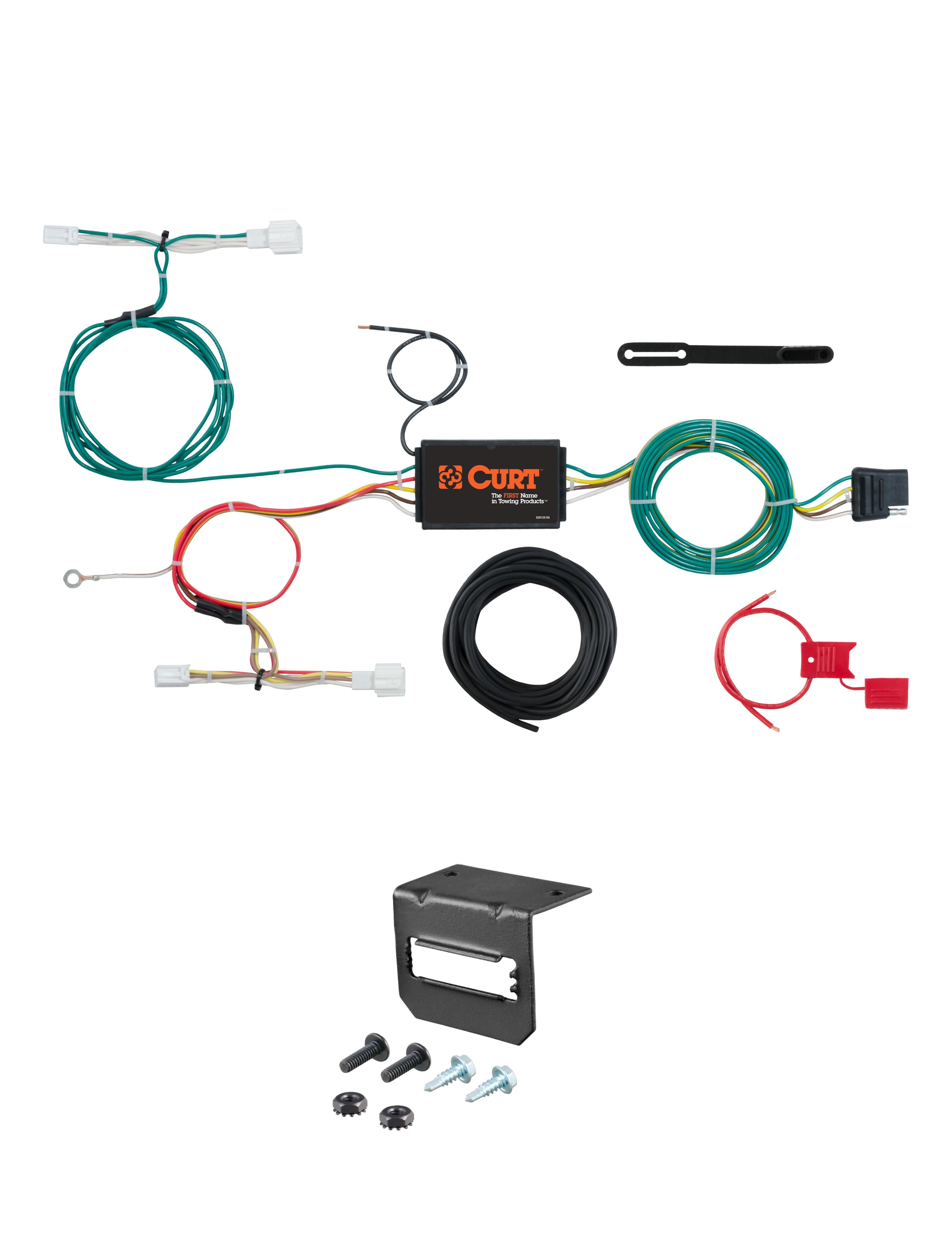
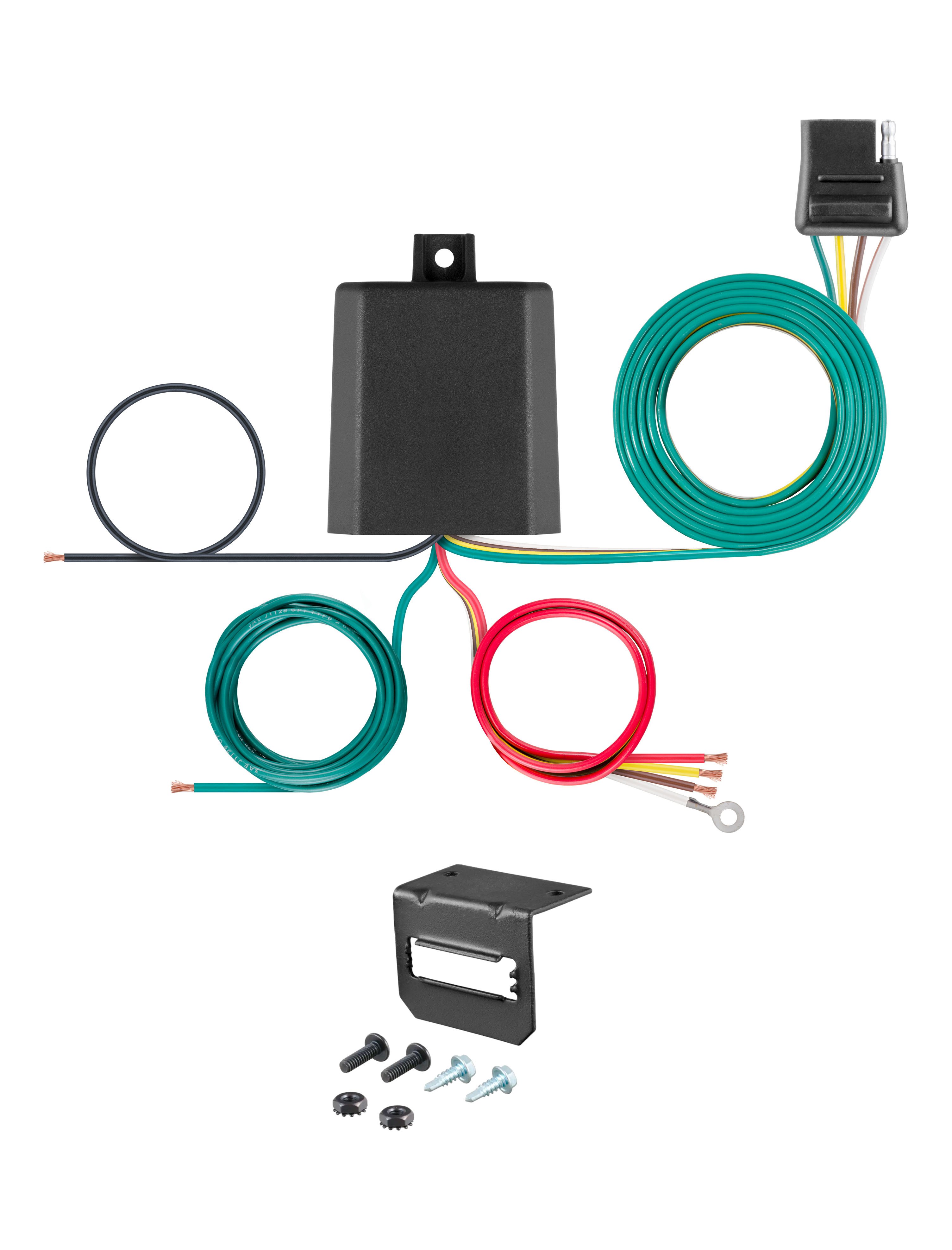
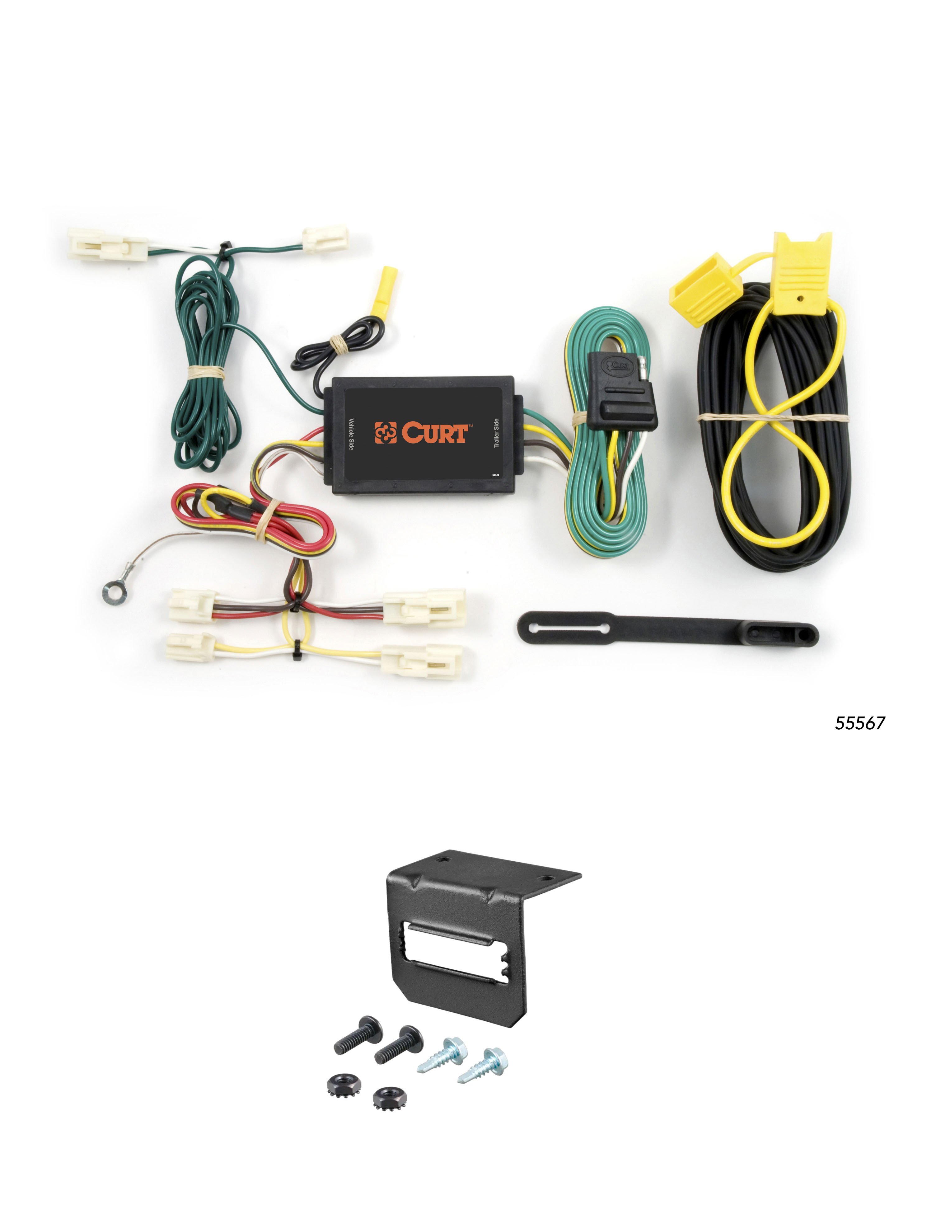
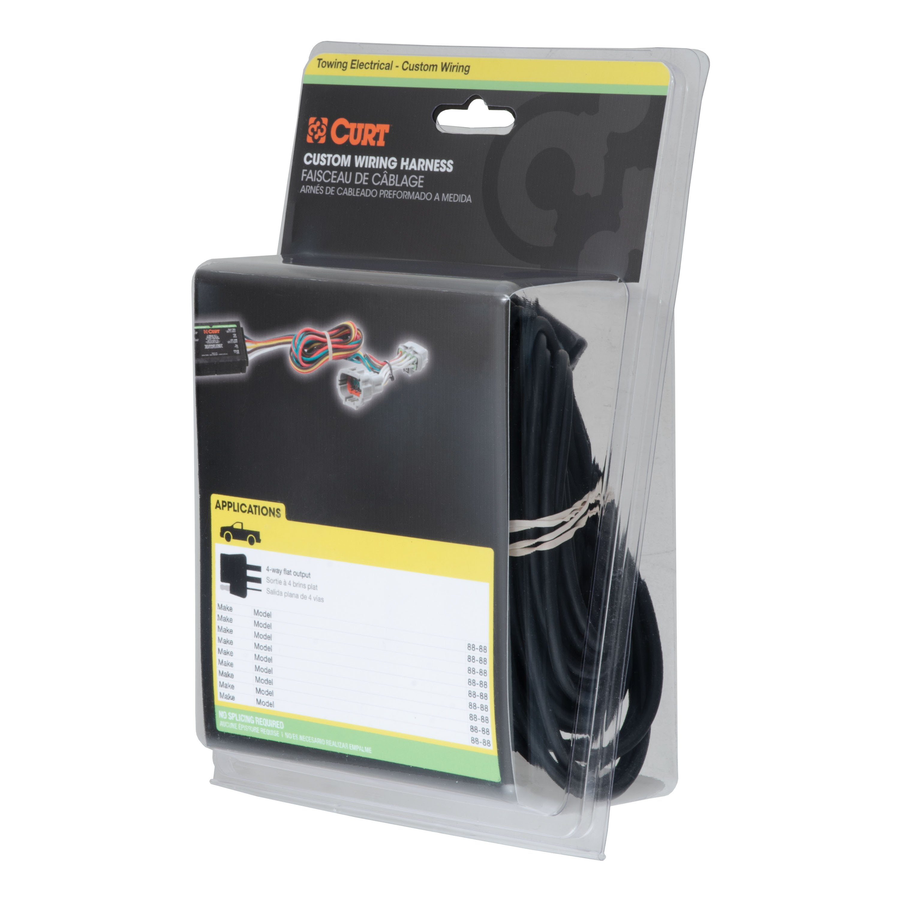
The kit includes the custom wiring harness with color-coded wires (yellow, red, green, white, and black), a black converter box, a ring terminal for the ground wire, a provided screw for grounding, double-sided tape for mounting the converter box, cable ties for securing loose wires, and a 4-flat dust cover. A separate CME-PCL-INS sheet is included with battery power wire routing instructions.
On the driver side, insert the custom wiring harness end with the yellow wire between the two-pin separated connectors and the red wire end between the three-pin connectors. Make sure the connectors are fully inserted with locking tabs in place. Take care not to damage the locking tabs during insertion.
Route the custom wiring harness end with the green wire to the passenger side behind the removed scuff panels. Insert the harness end with the green wire between the two-pin separated connectors and the red wire end between the three-pin connectors, matching the driver side procedure. Ensure the connectors are fully inserted with locking tabs in place.
Locate a suitable grounding point near the connector, such as an existing screw with nut in the vehicle frame. If no suitable point exists, drill a 3/32" pilot hole for the provided screw. The area must be free of rust, dirt and paint. Secure the white ground wire using the ring terminal and provided screw.
Drilling may be required. You must locate a suitable grounding point near the connector. If an existing screw with nut is available in the vehicle frame, no drilling is needed. If not, you must drill a 3/32" pilot hole for the provided ground screw.
Drill a 3/32" pilot hole for the provided ground screw. The area must be free of rust, dirt and paint before drilling. Check for miscellaneous items hidden behind or under surfaces before drilling to avoid damage and personal injury.
Before drilling, check for miscellaneous items that may be hidden behind or under any surface to avoid damage and personal injury. Ensure the drilling area is free of rust, dirt and paint. The manual does not specify what types of items to check for, so consult your vehicle owner's manual or contact the vehicle manufacturer for guidance on what may be behind the surface where you plan to drill.
The Curt 55567 uses the following wire colors: yellow wire (connects to two-pin separated connectors), red wire (connects to three-pin connectors), green wire (passenger side harness end), white wire (ground connection), and black wire (power connection from vehicle battery). The black converter box is mounted separately inside the vehicle.
The battery connection must be fuse-protected with a 10-amp maximum fuse. Exceeding this rating can cause loss of warranty, overheating and potential fire. Do not exceed the product rating or tow vehicle lamp load rating, whichever is lower.
Use a 10-amp maximum fuse for the battery connection. Do not exceed this rating or the tow vehicle lamp load rating, whichever is lower.
The Curt 55567 has the following circuit ratings: Signal Circuits – 3.0 amps per side; Tail/Running Circuits – 6.0 amps total. Do not exceed these ratings or the tow vehicle lamp load rating, whichever is lower.
Route the black power wire from the vehicle battery as shown on the included CME-PCL-INS sheet. The manual does not provide the routing details in the installation instructions; refer to the separate CME-PCL-INS sheet included with your kit for specific routing instructions.
Locate a flat spot inside the vehicle near the taillight and adhere the black converter box using the provided double-sided tape. The converter box should be mounted in a location that is accessible but out of the way.
When in use, route the 4-flat to the center of the vehicle and out of the trunk. When not in use, roll up and store in a convenient, out of the way location inside the trunk. Secure any loose wires with the provided cable ties to prevent tangling and damage.
The manual specifies circuit ratings (Signal Circuits – 3.0 amps per side; Tail/Running Circuits – 6.0 amps total) and a 10-amp maximum fuse rating for the battery connection. Do not exceed the product rating or tow vehicle lamp load rating, whichever is lower. Exceeding the product rating can cause loss of warranty, overheating and potential fire.
Exceeding the product rating can cause loss of warranty, overheating and potential fire. Do not exceed the product rating or tow vehicle lamp load rating, whichever is lower.
Once installed, test for proper function by using a test light or connecting a properly wired trailer. All steps must be followed to ensure the wiring harness will function properly before testing.
Test for proper function by using a test light or connecting a properly wired trailer. Ensure all installation steps have been completed before testing.
Reinstall all items removed during installation, including trim panels, scuff panels, cargo trays, and subwoofer units (if applicable). Install the provided 4-flat dust cover to help prevent corrosion. Test the wiring harness for proper function using a test light or properly wired trailer.
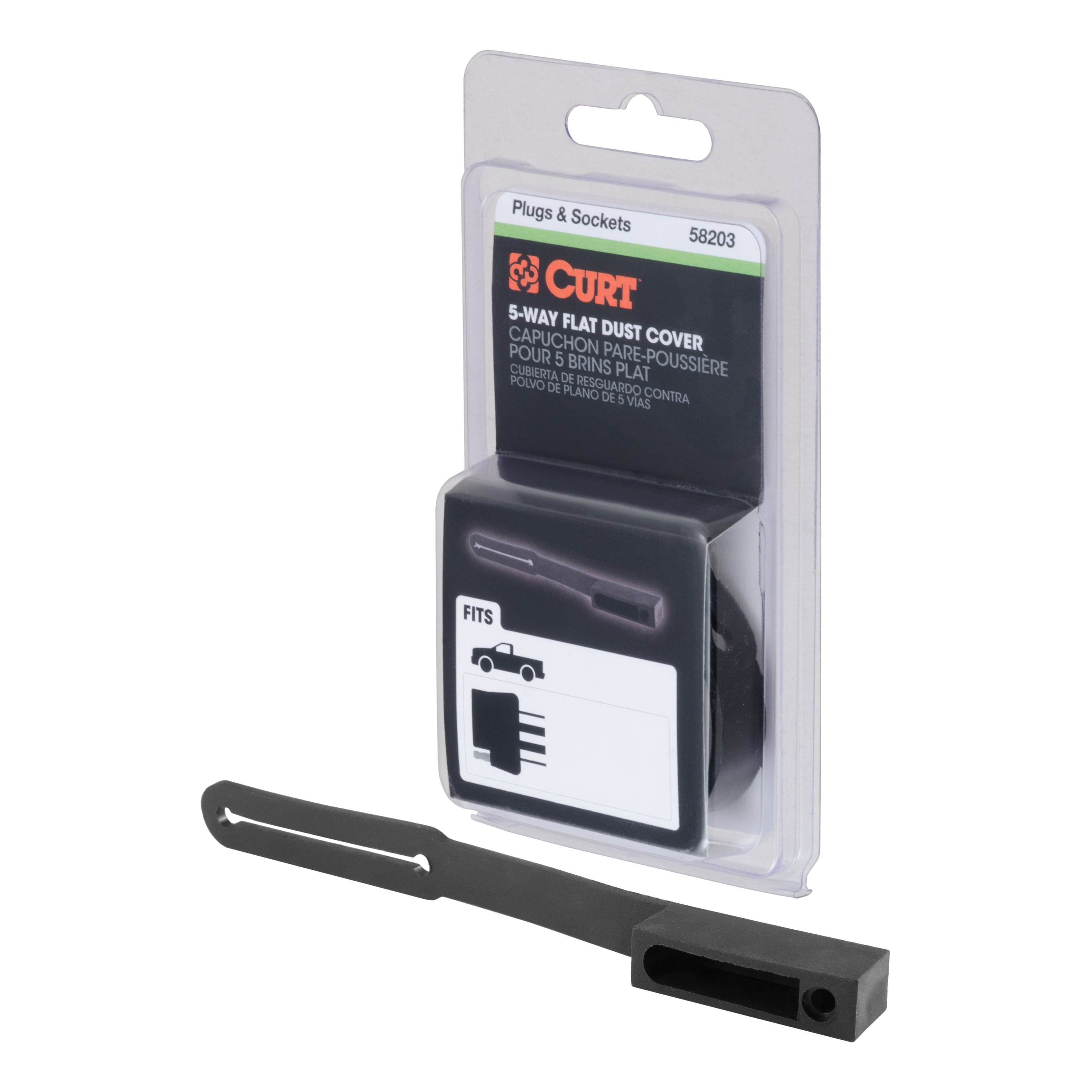
The provided 4-flat dust cover helps prevent corrosion of the connector. Install it after completing all installation steps and reinstalling removed items.
1. Remove the plastic scuff panel and pull back the felt trunk liner to access the vehicle wiring harness connectors. 2. Locate the vehicle taillight wiring harness connectors and separate them from the taillight housing, taking care not to damage the locking tabs. 3. Insert the custom harness end with yellow wire between the two-pin separated connectors and the red wire end between the three-pin connectors on the driver side. 4. Route the harness end with green wire to the passenger side and repeat the connector insertion. 5. Locate a suitable grounding point or drill a 3/32" pilot hole and secure the white ground wire with the ring terminal and provided screw. 6. Route the black power wire from the vehicle battery as shown on the included CME-PCL-INS sheet. 7. Mount the black converter box on a flat spot near the taillight using the provided double-sided tape. 8. Route the 4-flat to the center of the vehicle when in use; store it rolled up in the trunk when not in use. Secure loose wires with cable ties. 9. Reinstall all removed items and install the 4-flat dust cover.
1. Remove the plastic scuff panel and pull back the felt trunk liner. 2. On the driver side, use a 10mm socket to remove two nuts on the back of the taillight housing. Gently pull the housing rearward and separate the connectors from the taillight housing, taking care not to damage the locking tabs. Set the taillight assembly aside. 3. Insert the custom harness end with yellow wire between the two-pin separated connectors and the red wire end between the three-pin connectors on the driver side. 4. Route the harness end with green wire to the passenger side and repeat the connector insertion. 5. Locate a suitable grounding point or drill a 3/32" pilot hole and secure the white ground wire with the ring terminal and provided screw. 6. Route the black power wire from the vehicle battery as shown on the included CME-PCL-INS sheet. 7. Mount the black converter box on a flat spot near the taillight using the provided double-sided tape. 8. Route the 4-flat to the center of the vehicle when in use; store it rolled up in the trunk when not in use. Secure loose wires with cable ties. 9. Reinstall all removed items and install the 4-flat dust cover.
1. Remove the rear scuff panel and felt trunk liner to access the vehicle wiring harness connectors. 2. Remove the plastic nuts securing the cargo tray and remove the tray. Locate the vehicle taillight wiring harness connectors and separate them from the taillight housing, taking care not to damage the locking tabs. 3. Insert the custom harness end with yellow wire between the two-pin separated connectors and the red wire end between the three-pin connectors on the driver side. 4. Route the harness end with green wire to the passenger side and repeat the connector insertion. 5. Locate a suitable grounding point or drill a 3/32" pilot hole and secure the white ground wire with the ring terminal and provided screw. 6. Route the black power wire from the vehicle battery as shown on the included CME-PCL-INS sheet. 7. Mount the black converter box on a flat spot near the taillight using the provided double-sided tape. 8. Route the 4-flat to the center of the vehicle when in use; store it rolled up in the trunk when not in use. Secure loose wires with cable ties. 9. Reinstall all removed items and install the 4-flat dust cover.
1. Remove the rear scuff panel and felt trunk liner to access the vehicle wiring harness connectors inside the rear cargo area. 2. Locate the vehicle taillight wiring harness connectors and separate them from the taillight housing, taking care not to damage the locking tabs. 3. Insert the custom harness end with yellow wire between the two-pin separated connectors and the red wire end between the three-pin connectors on the driver side. 4. Route the harness end with green wire to the passenger side and repeat the connector insertion. 5. Locate a suitable grounding point or drill a 3/32" pilot hole and secure the white ground wire with the ring terminal and provided screw. 6. Route the black power wire from the vehicle battery as shown on the included CME-PCL-INS sheet. 7. Mount the black converter box on a flat spot near the taillight using the provided double-sided tape. 8. Route the 4-flat to the center of the vehicle when in use; store it rolled up in the trunk when not in use. Secure loose wires with cable ties. 9. Reinstall all removed items and install the 4-flat dust cover.
1. Open the vehicle tailgate and remove the jack storage compartment door on the driver side. 2. Remove the five screws securing the rear scuff panel. Using a trim panel removal tool, carefully pry the rear scuff panel away from the vehicle, taking care not to damage the alignment tabs. 3. Remove the two Phillips screws connecting the trim panel to the vehicle floor on both sides. Remove the cargo clips and access panels to gain access to the vehicle wiring. If equipped with an optional subwoofer unit, remove the access panel below it, carefully remove the front trim/grill assembly, use a 10mm socket to remove the four 10mm bolts holding the subwoofer unit, disconnect the harness retainer clip, and pull out the subwoofer unit. 4. Using a trim panel removal tool, carefully pull back the interior trim panels on both sides. 5. Locate the vehicle taillight wiring harness connectors and route the custom harness ends with red and yellow wires behind the trim panel up to the access panel location. 6. Insert the custom harness end with yellow wire between the two-pin separated connectors and the red wire end between the three-pin connectors on the driver side. 7. Route the harness end with green wire to the passenger side and repeat the connector insertion. 8. Locate a suitable grounding point or drill a 3/32" pilot hole and secure the white ground wire with the ring terminal and provided screw. 9. Route the black power wire from the vehicle battery as shown on the included CME-PCL-INS sheet. 10. Mount the black converter box on a flat spot near the taillight using the provided double-sided tape. 11. Route the 4-flat to the center of the vehicle when in use; store it rolled up in the trunk when not in use. Secure loose wires with cable ties. 12. Reinstall all removed items and install the 4-flat dust cover.
Only if your FJ Cruiser is equipped with an optional subwoofer unit. If it is equipped with a subwoofer, you must remove it to gain access to the vehicle wiring harness connectors. The removal process involves removing the access panel below the subwoofer, carefully removing the front trim/grill assembly (taking care not to damage the eight clips), using a 10mm socket to remove the four 10mm bolts holding the subwoofer unit, disconnecting the harness retainer clip, and pulling out the subwoofer unit. If your vehicle is not equipped with a subwoofer, skip these steps and proceed directly to pulling back the interior trim panels.
1 compatible vehicles
| Year | Make & Model | Notes |
|---|---|---|
| 2003 - 2008 | Mazda 6 | Sedan |
Total for 4 items:
$163.71$168.85
No reviews have been added for this product.