
2018-2021 BMW X3 Draw-tite Hidden Hitch Completely Hidden Trailer Hitch 2 Inch Removable Receiver Bundle w/ Plug-n-Play T-One Wiring HarnessDraw-titeOriginal price was $780.00. Current price is $684.09.Out of Stock
View productOur in-house experts typically reply within one business day.

Draw-tite
Verify Fitment
Select your vehicle to confirm this part fits.






Always the correct part
We know our products
Quality Products
Free Shipping!
Always the correct part
We know our products
Quality Products
Free Shipping!
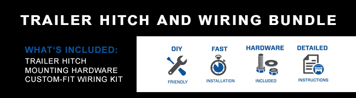
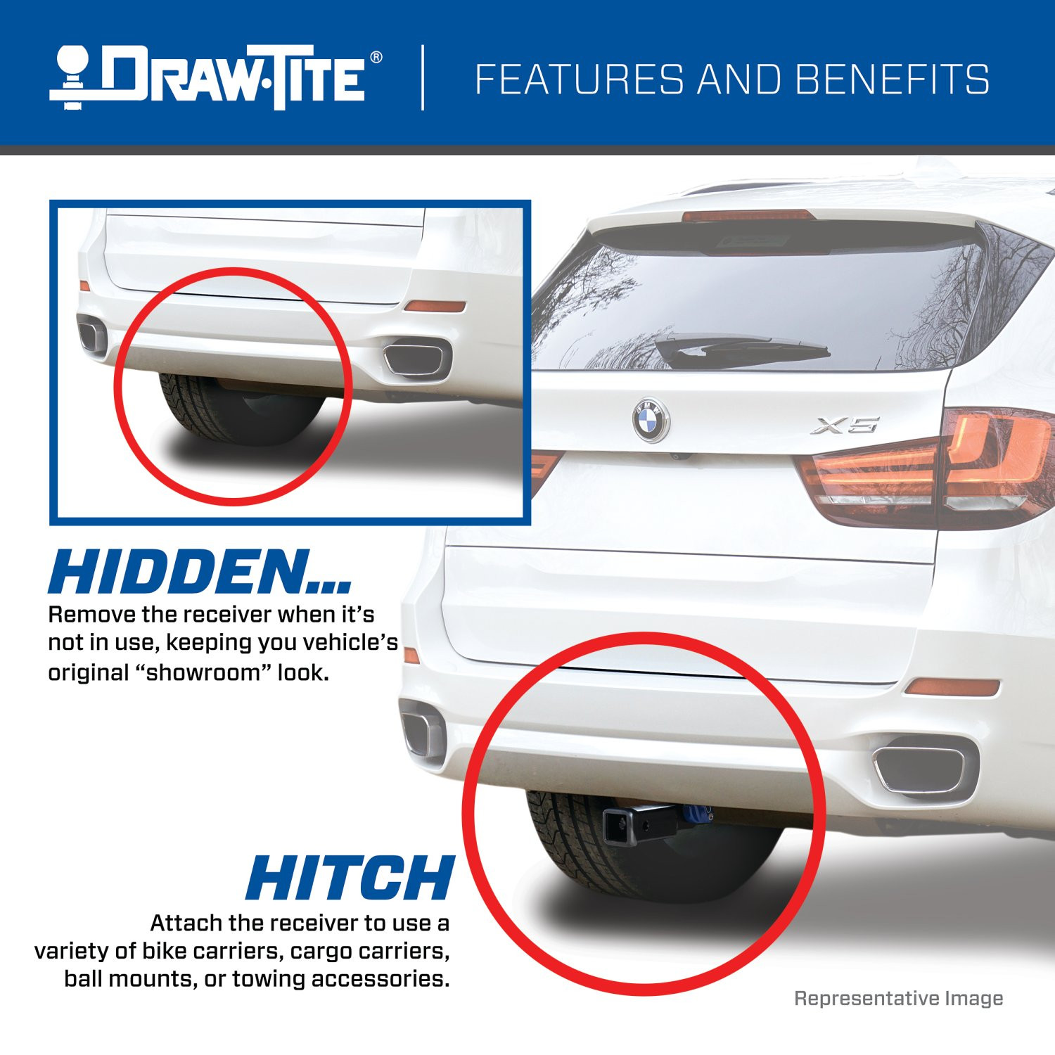
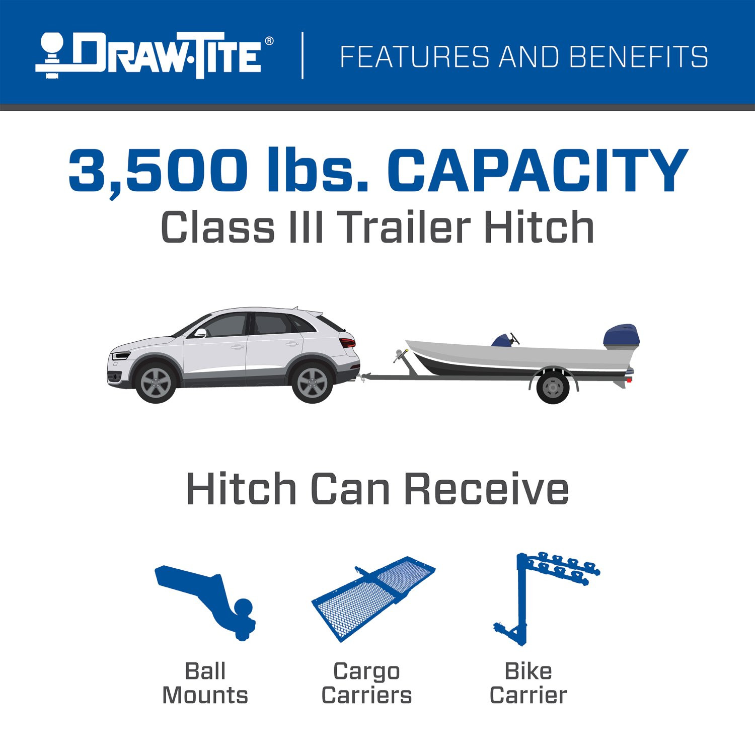
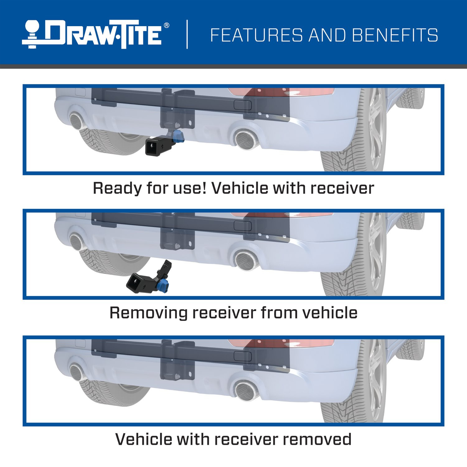
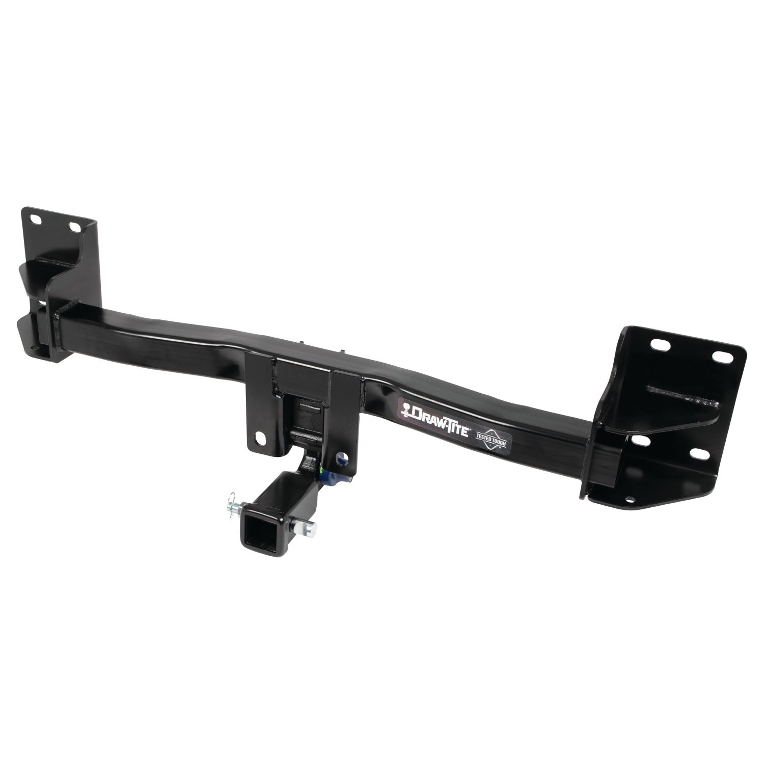
Made from welded steel with a black premium finish, the Hidden Hitch series of hitches are custom designed to ensure a superior fit for each make and model vehicle. Each Hidden Hitch is designed with a two-inch receiver opening to fit a number of different accessory attachments like bike racks, cargo carriers, and more! Draw-Tite Hidden Hitches are rated for 3,500 pounds gross trailer weight (GTW) and are best suited for use with accessories or light-duty towing. The integrated anti-theft lockable receiver ensures added safety when the hitch is in use, while the included anti-rattle hitch pin provides premium performance and security. When you are not using the Hidden Hitch, you can store the removeable receiver, anti-rattle pin, and weather covers in the hard sided carrying case that is included with your purchase.
These dependable, premium custom hitches are manufactured for 2007-2018 BMW X5 and attach to your vehicle?s frame behind the bumper for a luxuriously clean appearance. Hidden Hitch trailer hitches have a sleek black powder coat finish for superior rust and corrosion resistance and come complete with all the mounting hardware needed for installation. Plus, each hitch is tested to meet - and exceed - V-5 and SAE J684 standards and is backed by a nationwide lifetime limited warranty.
So, take that extra cooler out to the lake, hit the bike trails in the park, or hook up that utility trailer and tackle your honey-do home repairs. When you are done, remove the evidence (i.e., the removeable receiver), and go for a cruise. With the Hidden Hitch, you can do it all! Brought to you by Draw-Tite, North America?s Favorite Hitch.

Draw-Tite has designed custom-fit trailer hitches since 1946 and is one of North America's most widely fitted hitch brands. Receiver hitches use solid all-welded construction and low-profile designs that follow modern vehicle contours, install with minimal bumper cutting or drilling, meet or exceed V5 CSA and SAE J684 standards, and carry a limited lifetime warranty.
Draw-Tite has been leading custom-fit trailer hitch design and engineering since its founding in 1946, and it remains one of the most widely fitted hitch brands in North America. The company's stated approach is straightforward: every hitch is tested rigorously so that it performs well beyond published industry standards, a philosophy it markets as Tested Tough. It sits within the Horizon Global towing group alongside Reese, Fulton, Bulldog, Tekonsha, Bargman and Wesbar.
Custom fit is the defining characteristic. Rather than adapting a universal design, Draw-Tite engineers a trailer hitch for a specific make, model and model year, so it bolts to existing frame locations with minimal bumper cutting or drilling. Low-profile designs follow the rear contours and aerodynamic styling of modern vehicles, which matters more than it once did now that rear fascias are shaped and sensor-equipped. Construction is solid all-welded steel for maximum strength, and every hitch meets or exceeds V5 CSA and SAE J684 standards and is backed by a nationwide limited lifetime warranty.
The range spans receiver sizes and classes to suit different loads, from 1-1/4 inch receivers for bike racks, cargo carriers and light trailers up through 2 inch receivers for heavier towing. Front mount hitches add a receiver at the front of the vehicle for winch mounts, snow plows, spare carriers and precise trailer positioning.
The Hidden Hitch series takes concealment further by mounting behind the vehicle's rear fascia, so the vehicle keeps its factory appearance until a removable receiver is fitted. Each is custom designed per make and model for a no-drill installation that does not compromise ground clearance, rated for up to 3,500 pounds gross trailer weight and 350 pounds tongue weight. Matching plug-and-play wiring completes the towing system.
Experts available to answer your questions
Call 888-634-94941 compatible vehicles
| Year | Make & Model | Notes |
|---|---|---|
| 2015 - 2018 | BMW X5 | Except M Sport Package |
The 2015-2018 BMW X5 Except M Sport Package Draw-tite Hidden Hitch Completely Hidden Trailer Hitch 2 Inch Removable Receiver Bundle w/ Plug-n-Play T-One Wiring Harness (Part #DTB76903-118743) fits 2015-2018 BMW X5 models. The 2018 model year is the last year covered by this part number. For newer models, check for an updated version.
The 2015-2018 BMW X5 Except M Sport Package Draw-tite Hidden Hitch Completely Hidden Trailer Hitch 2 Inch Removable Receiver Bundle w/ Plug-n-Play T-One Wiring Harness (Part #DTB76903-118743) fits the following vehicles: 2015-2018 BMW X5. Always verify your specific year, make, and model before ordering.
Yes, the 2015-2018 BMW X5 Except M Sport Package Draw-tite Hidden Hitch Completely Hidden Trailer Hitch 2 Inch Removable Receiver Bundle w/ Plug-n-Play T-One Wiring Harness (Part #DTB76903-118743) is designed to fit the 2015-2018 BMW X5.
The 2015-2018 BMW X5 Except M Sport Package Draw-tite Hidden Hitch Completely Hidden Trailer Hitch 2 Inch Removable Receiver Bundle w/ Plug-n-Play T-One Wiring Harness (Part #DTB76903-118743) Refer to the included instructions for installation details. Basic hand tools are typically all you need.
Yes, part number 76903 is designed for 2011–2018 BMW X5 models. Visit the Horizon Global website for the most up-to-date information regarding specific application years and trim levels.
The 76903 is a weight-carrying hitch with a maximum gross trailer weight (GTW) of 3,500 lb (1,589 kg) and a maximum tongue weight of 350 lb (159 kg). Do not exceed the lower of your vehicle manufacturer's towing rating or these limits.
Required tools: ratchet, torque wrench, 10 mm and 18 mm sockets, 6 inch socket extension, safety glasses, utility knife, tape measure, marker, plastic rivet gun, drill, and 3/16 inch drill bit. Silicone sealant is also needed.
No, drilling is not required for the hitch installation itself. However, a drill and 3/16 inch bit are listed as required equipment, likely for removing plastic rivets from the wheel well molding during bumper fascia removal.
All M12 fasteners must be tightened to 65 lb-ft (88 N·m). The housing attachment bolt (M12) is tightened separately to 92 lb-ft (125 N·m).
Yes, the rear bumper fascia must be removed. This involves removing plastic rivets from the wheel well molding, fascia screws, reflectors, and tail lights. The impact bar must also be removed and kept for the hitch installation.
Always wear your seatbelt. Load the trailer heavier in front. Do not exceed the lower of your vehicle manufacturer's rating or 3,500 lb GTW / 350 lb tongue weight. Slow down when towing and never exceed posted speed limits. If excess sway occurs, take your foot off the gas pedal and hold the steering wheel steady; do not apply brakes or speed up.
Check all fasteners and the ball are properly tightened periodically. Proper torque is essential to keep the hitch secure to the vehicle when towing. If the hitch is removed, plug all holes in the trunk pan or body panels to prevent water and exhaust fume entry.
The package includes the hitch receiver with weather covers, fastener kit 76903F (6 plastic rivets, 1 cable tie, 2 M12 bolts, 2 washers, 2 prevailing torque nuts), fastener kit 76903F2 (1 warning card, 2 warning labels), and an attached key for the blue handle lock. A separate receiver kit (76900N) is required for receiver installation and use.
The 76903 is designed for 2011–2018 BMW X5 models only. For information about fitment on other model years, visit the Horizon Global website or contact technical support at 800-632-3290.
The average installation time for professional installers is 45 minutes. If you do not feel comfortable performing this installation on your own or need assistance, contact a professional installer.
1. Remove the receiver and weather covers from the case. 2. Unlock the blue handle using the attached key and remove the housing by pressing the handle and rotating clockwise until you hear a click. 3. Install the top/bottom weather cover to the housing. 4. Attach the housing to the hitch using an M12 bolt, flat washer, and prevailing torque nut. 5. Tighten the housing fasteners to 92 lb-ft (125 N·m).
Eight existing flange nuts from the removed impact bar are used to mount the hitch. These are installed loosely first, then tightened to 65 lb-ft (88 N·m) using a torque wrench. All fasteners are M12 grade.
Yes. When you remove the impact bar in step 4, keep the nuts for hitch installation. These eight existing flange nuts are used to mount the hitch to the vehicle. Return the impact bar itself to the vehicle owner.
Fascia trimming is required only for 2013 and older models. For 2013 and older X5 models, trim the fascia using a utility knife at the bottom center, creating a cutout 8.5 inches wide by 5 inches tall. Obtain the vehicle owner's approval before cutting.
Insert a small center punch or drill bit into the center of each rivet to push the pin through. The rivets cannot be reused; replacement rivets are supplied in the fastener kit (part 110269). There are 2 or 3 rivets on each side of the wheel well molding.
1. Remove 2–3 plastic rivets from each side of the wheel well molding. 2. Pull back the wheel well molding and remove fascia screws (1–2 per side). 3. Remove 6 screws from the bottom of the fascia (3 per side). 4. Remove reflectors by releasing the clip underneath the bumper and remove screws behind them. 5. Remove tail lights by opening trunk side panels, unclipping the electrical harness, and pulling the lights rearward (remove 2 screws if present). 6. Open the bottom tailgate at 45° and note the tabs retaining the fascia lip. 7. Pull the fascia outward and rearward, unclip the electrical on the passenger side, and remove.
1. Reattach the backup sensor (if present) using the cable tie and the bottom hole on the hitch bracket. 2. Reattach the electrical harness on the passenger side. 3. Reattach the fascia using the supplied plastic rivets (part 110269), ensuring all fascia tabs are correctly aligned. 4. Reattach the tail lights and reflectors.
Apply the two warning labels (part of fastener kit 76903F2) to the top of the receiver and the door jamb respectively. Keep the warning card (also in kit 76903F2) in the glove compartment for future reference.
Silicone sealant is used to seal around the opening on the end panel on both sides of the vehicle before raising the hitch into position. This prevents water and exhaust fume entry.
The 76903 is covered by a Limited Lifetime Warranty from Horizon Global Americas Inc. The warranty covers material defects in materials and workmanship, excluding ordinary wear and tear. The warranty is valid only if products are installed, maintained, and used according to the instructions, and are not damaged by misuse, neglect, improper installation, or accident. Product replacement is the sole remedy. To make a claim, contact Horizon Global at 47912 Halyard Drive, Suite 100, Plymouth, MI 48170, or call 1-800-632-3290.
No. The manual explicitly states: DO NOT cut, weld, or modify this receiver. Do not cut access or attachment holes with a torch. Modifications will void the warranty and compromise the structural integrity and safety of the hitch.
The 76903 accepts ball mounts with a maximum rise of 10.5 inches (distance from center of ball hole to center of pin hole) and a minimum rise of 0.75 inches (distance from top of shank to top of ball platform). Specific ball mount part numbers are not listed in the manual; consult the Horizon Global website or contact technical support for compatible options.
Two quick-link safety chain attachment options are available (sold separately): #49131 (5/16 inch) with a maximum GTW of 3,500 lb, and #44133 (3/8 inch) with a maximum GTW of 3,500 lb. Do not exceed the hitch's maximum towing capacity of 3,500 lb GTW.
Yes. The impact bar must be removed using an 18 mm deep socket. If a backup sensor is present, disconnect its wiring. Lower the tailgate to access the upper mounting fasteners. Keep the nuts from the impact bar for hitch installation, and return the impact bar itself to the vehicle owner.
Use a torque wrench to tighten all M12 fasteners to 65 lb-ft (88 N·m). The housing attachment bolt (M12) is tightened separately to 92 lb-ft (125 N·m). Proper torque is essential to keep the hitch secure to the vehicle when towing. Check fasteners periodically to ensure they remain tight.
Install the eight existing flange nuts loosely first (step 5), then tighten all fasteners to torque specifications in step 6. Tighten all M12 fasteners to 65 lb-ft (88 N·m) using a torque wrench.
If excess sway occurs, take your foot off the gas pedal and hold the steering wheel as steady as possible. Do not apply your brakes and do not speed up. Reduce speed and maintain steady steering until the sway subsides.
If the hitch is removed, plug all holes in the trunk pan or other body panels to prevent entry of water and exhaust fumes. This protects the vehicle's interior and mechanical systems.
A hitch or ball which has been damaged should be removed and replaced immediately. Do not continue towing with a damaged hitch, as it compromises safety and may cause loss of the trailer.
The manual states that the average installation time for professional installers is 45 minutes. If you do not feel comfortable performing this installation on your own or are in need of assistance, contact a professional installer.
The M12 housing attachment bolt must be tightened to 92 lb-ft (125 N·m). This is separate from the main hitch fasteners, which are tightened to 65 lb-ft (88 N·m).
The fastener kit includes two M12 bolts, 1.75 x 100 mm, Class 10.9. These are used with flat washers (7/16 inch) and prevailing torque nuts (M12 x 1.75, Class 10) to attach the housing to the hitch.
Use the key attached to the receiver to unlock the blue handle. Once unlocked, press the handle and rotate it clockwise until you hear a click sound. This releases the housing from the receiver.
The cable tie (part 18101) is used to reattach the backup sensor to the hitch bracket if one is present on the vehicle. It is installed through the bottom hole on the hitch bracket during step 8 of the installation.
The fastener kit 76903F includes 6 plastic rivets (part 110269). These are used to reattach the rear bumper fascia after installation. The original rivets removed during disassembly cannot be reused.
The warning card (part of fastener kit 76903F2) should be kept in the glove compartment for future reference. The two warning labels should be applied to the top of the receiver and the door jamb to alert users to important safety information about the hitch.
The maximum tongue weight for the 76903 is 350 lb (159 kg). Do not exceed this limit, as it can affect vehicle handling and stability.
Load the trailer heavier in front. This helps maintain proper weight distribution and improves towing stability. Ensure the tongue weight does not exceed 350 lb.
Slow down when towing and never exceed any posted speed limit. Reduce your normal driving speed to improve control and stability when towing a trailer.
The 76903 complies with safety specifications and requirements for connecting devices and towing systems of the state of New York, V.E.S.C. Regulation V-5 and SAE J684.
Always wear safety glasses when installing the hitch. The manual also recommends observing safety precautions when working beneath a vehicle and wearing eye protection.
Open the bottom tailgate at a 45° angle. This allows you to see and access the tabs that retain the fascia lip, which must be noted before pulling the fascia off.
Lower the tailgate to access the upper mounting fasteners of the impact bar. This allows you to remove the bar completely before installing the hitch.
1. Open the side panels in the trunk. 2. Unclip the electrical harness. 3. Pull the tail light rearward. 4. On some models, remove 2 screws from under the tail light. The tail lights must be removed to access the fascia screws behind them.
The reflectors can be removed by releasing the clip that holds them in place. Access the clip from underneath the bumper. Once removed, you can access the screws behind the reflectors that hold the fascia.
The fascia is held by multiple screws: 1–2 screws on each side behind the wheel well molding (depending on model), 6 screws from the bottom of the fascia (3 per side), and screws behind the reflectors. The exact total depends on your specific model year.
An 18 mm deep socket is required to remove the impact bar fasteners.
When you press the blue handle and rotate it clockwise, you will hear a click sound. This indicates the housing has been properly released from the receiver.
For 2013 and older models, trim the fascia at the bottom center, creating a cutout 8.5 inches wide by 5 inches tall (4.25 inches on each side of center, 5 inches in height). Use a utility knife and obtain the vehicle owner's approval before cutting.
The fascia support is shown in Figure 1 and helps maintain the alignment and position of the fascia during and after installation. It ensures the fascia tabs are correctly aligned when reattached.
When reattaching the fascia in step 8, ensure that all fascia tabs are correctly aligned. The tabs should fit into the slots on the vehicle body. Refer to Figure 1 for the proper alignment of the fascia support and tabs.
The studs are the mounting points on the vehicle frame where the hitch fasteners attach. The eight existing flange nuts from the impact bar are installed on these studs to secure the hitch to the vehicle.
The end panel is part of the vehicle's rear structure. Silicone sealant is applied around the opening on the end panel on both sides before the hitch is raised into position to prevent water and exhaust fume entry.
Raise the hitch into position and loosely install the eight existing flange nuts (step 5). Use silicone sealant to seal around the opening on the end panel on both sides before raising the hitch. Once positioned, tighten all fasteners to the specified torque in step 6.
The 76903 is a weight-carrying hitch. It has a maximum gross trailer weight of 3,500 lb (1,589 kg) and a maximum tongue weight of 350 lb (159 kg). Weight-distributing specifications are listed as N/A.
Scan the QR code provided in the manual or visit http://qr.towingproducts.net/qrproducts/qr-product for step-by-step photo installation instructions.
Scan the QR code provided in the manual or visit http://qr.towingproducts.net/qrproducts/qr-product for safe towing tips.
Contact Horizon Global technical support at 800-632-3290 or email TechnicalSupport@horizonglobal.com. You can also visit their website at www.horizonglobal.com. For warranty claims, contact their principal address: 47912 Halyard Drive, Suite 100, Plymouth, MI 48170.
Check all fasteners periodically to ensure they remain tight. If fasteners are loose, use a torque wrench to retighten all M12 fasteners to 65 lb-ft (88 N·m). Proper torque is essential to keep the hitch secure to the vehicle when towing. Loose fasteners can compromise safety and cause hitch failure.
Ensure you are using the correct key attached to the receiver. Press the blue handle firmly while rotating it clockwise. You should hear a click sound when the housing is properly released. If the handle does not click, do not force it; contact Horizon Global technical support at 800-632-3290.
Ensure all fascia tabs are correctly aligned with the slots on the vehicle body. Refer to Figure 1 for proper alignment. Gently adjust the fascia position before fully tightening the rivets. If tabs are damaged or misaligned, the fascia may need to be replaced.
If the hitch is removed, plug all holes in the trunk pan or other body panels to prevent entry of water and exhaust fumes. If water or fumes are already present, ensure the silicone sealant around the end panel openings (applied in step 5) is intact and properly sealed. Reapply sealant if necessary.
A hitch which has been damaged should be removed and replaced. Do not attempt to repair or continue using a damaged hitch, as it compromises safety and may cause loss of the trailer. Contact Horizon Global at 800-632-3290 for warranty replacement options.
Ensure the backup sensor wiring was properly reconnected in step 8. The sensor should be reattached using the cable tie and the bottom hole on the hitch bracket. Check that the electrical harness on the passenger side is fully clipped in. If the sensor still does not work, consult a professional installer or contact Horizon Global technical support at 800-632-3290.
The fastener kit includes 6 replacement plastic rivets (part 110269). If a rivet breaks during installation, use one of the spare rivets to reattach the fascia. Ensure the rivet is fully seated and the fascia is secure before towing.
If excess sway occurs while towing, take your foot off the gas pedal and hold the steering wheel as steady as possible. Do not apply your brakes and do not speed up. Reduce speed and maintain steady steering. Excessive sway may indicate improper load distribution, tongue weight exceeding 350 lb, or loose hitch fasteners. Check fastener torque and load distribution.
Verify the ball mount specifications: maximum rise of 10.5 inches (distance from center of ball hole to center of pin hole) and minimum rise of 0.75 inches (distance from top of shank to top of ball platform). If your ball mount does not meet these specifications, it is not compatible with the 76903. Contact Horizon Global at 800-632-3290 for compatible ball mount options.
The T-One® T-Connector is a trailer wiring interface that connects between your vehicle's taillight wiring harness and a trailer connector. It allows you to connect a trailer to your vehicle's electrical system for brake lights, turn signals, and running lights. The system includes a black box module, wiring harness with yellow and green connectors for the driver and passenger sides, a white ground wire, a black 12 ga. power wire, a 15 amp fuse holder, and cable ties for securing the harness.
The manual shows this T-Connector is designed for the BMW X5. However, the specific model year or generation is not stated in the manual. Contact the manufacturer or your installer to confirm compatibility with your exact model year and generation, as fitment may vary.
You will need: trim panel remover, 10 mm socket and ratchet or 10 mm wrench, drill with 3/32" drill bit, 1/4" socket, wire crimpers, wire cutters, Phillips head screwdriver, and a test probe. A test light or trailer is also required to verify the installation after completion.
Yes. You must disconnect the vehicle's negative (-) battery cable before connecting the power wire to the positive battery terminal. This is a critical safety step. After all other connections are complete and the fuse is installed in the fuse holder, you will reconnect the negative battery cable.
The taillight wiring harness is located on both the driver and passenger sides of the vehicle. To access it, you must first open the hatch and partially remove the plastic threshold cover, side panels, and cargo trays. Then partially remove the rear interior trim panels on both sides. The taillight connector will be inside the rear cargo area.
On the driver's side, insert the T-Connector end with the yellow wire between the vehicle's taillight wiring connectors and lock into place, ensuring the locking tabs are fully engaged. Route the connector with the green wire down the threshold to the passenger side. On the passenger's side, insert the T-Connector end with the green wire between the vehicle's taillight connectors and lock into place. Ensure all connectors are fully inserted with locking tabs in place. Clean all connector surfaces before insertion.
Yes. You must drill a 3/32" hole to secure the white ground wire. Locate a suitable grounding point near the connector on the vehicle's frame or crossmember (do not drill into the vehicle floor or bed). Clean dirt and rustproofing from the area, drill the hole, and secure the white wire using the eyelet and screw provided. Always verify what is behind any surface before drilling to avoid damage to the vehicle or personal injury.
You need a 3/32" drill bit to create the hole for the white ground wire eyelet.
Option 1: Route the black 12 ga. power wire through the trim panels and down the threshold to the vehicle battery in the rear cargo area on the driver's side near the threshold. Option 2: Route the black wire along the exterior frame or follow existing wiring along the thresholds into the engine compartment up to the battery. If using Option 2, avoid hot pipes, heat shields, the fuel tank, and any other points that may pinch or break the wire. Choose the option that best suits your vehicle layout.
The power wire is black and 12 ga. (12 gauge). This wire connects from the T-Connector box to the vehicle's positive battery terminal through the fuse holder.
Install a 15 amp fuse into the yellow fuse holder provided. The fuse holder is connected between the black 12 ga. power wire and the vehicle's positive battery cable using a yellow butt connector.
The T-Connector has three main wires: yellow wire (driver-side taillight connector), green wire (passenger-side taillight connector), white wire (ground connection to vehicle frame or crossmember), and black 12 ga. wire (power connection to vehicle battery positive terminal). The yellow and green wires are inserted between the vehicle's existing taillight connectors.
Mount the black box module on a flat surface in an out-of-the-way location to prevent damage or rattling. Secure the remainder of the harness with the cable ties provided, being careful to avoid any areas that would pinch, cut, or melt the wire.
Store the 4-flat connector in the rear cargo area when not in use. When in use, pull the 4-flat connector through the door and close the door. Be careful not to pinch the harness in the door latch.
After installation is complete, test and verify the installation with a test light or by connecting a trailer. For the initial test, reset the vehicle's electrical system by temporarily removing the key from the ignition. All connections must be complete for the T-Connector to function properly. If using a test light, check that all trailer light circuits are functioning correctly.
Do not exceed the lower of the towing manufacturer's rating (including in your vehicle owner's manual) or the specific amperage ratings stated on the product. The manual does not specify the exact amperage rating of this T-Connector. Check the product label or contact the manufacturer for the specific amperage rating.
Always wear safety glasses during installation. Read and follow all warnings and cautions printed on the tow vehicle's battery. Verify what is behind any surface before drilling to avoid damage to the vehicle or personal injury. Do not drill into exposed surfaces. When routing wires, avoid hot pipes, heat shields, the fuel tank, and any areas that may pinch or break the wire. Do not pinch the harness in the door latch. Overloading circuits can cause fires, so do not exceed stated product ratings.
You must partially remove: the plastic threshold cover, side panels, cargo trays, and rear interior trim panels on both the driver and passenger sides of the vehicle. Several trim panel fasteners will need to be removed. Set aside all items removed and be careful not to damage parts. After installation, replace both access panels, spare tire cover, cargo floor hatch, and cargo nets.
Trim panel remover, 10 mm socket/ratchet or wrench, drill with 3/32" bit, 1/4" socket, wire crimpers, wire cutters, Phillips screwdriver, and test probe. You'll also need a test light or trailer to verify installation.
Yes. You must drill a 3/32" hole to secure the white ground wire to the vehicle frame or crossmember. Always verify what is behind the surface before drilling.
Yes. Disconnect the vehicle's negative (-) battery cable before connecting the power wire. Reconnect it after the fuse is installed and all other connections are complete.
A 15 amp fuse is installed in the yellow fuse holder provided with the kit.
Test with a test light or by connecting a trailer. Reset the vehicle's electrical system by temporarily removing the ignition key. Verify all trailer light circuits are functioning.
Do not exceed the lower of the towing manufacturer's rating or the specific amperage rating stated on the product. The manual does not specify the exact amperage rating; check the product label.
On Sale Today
Original price was $780.00. Current price is $670.02.You save $109.98 (14%)
Free Shipping
Ships free on all orders
 Authorized Dealer


FREE ShippingFREE SHIPPING
Estimated delivery Wed, Sep 16 - Sat, Sep 19
Order before 2 PM EST Monday–Friday for same-day processing
Guaranteed safe & secure checkout
No reviews have been added for this product.