

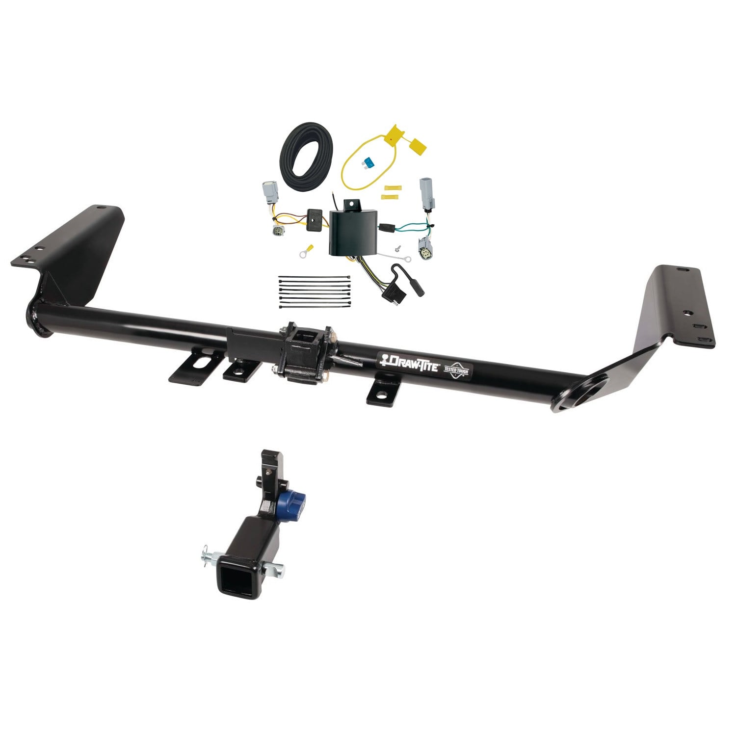
2018-2021 BMW X3 Draw-tite Hidden Hitch Completely Hidden Trailer Hitch 2 Inch Removable Receiver Bundle w/ Plug-n-Play T-One Wiring HarnessDraw-titeOriginal price was $780.00. Current price is $684.09.Out of Stock
View productOur in-house experts typically reply within one business day.

Draw-tite
Verify Fitment
Select your vehicle to confirm this part fits.
2022 - 2024 BMW X3
Confirmed to Fit





Always the correct part
We know our products
Quality Products
Free Shipping!
Always the correct part
We know our products
Quality Products
Free Shipping!

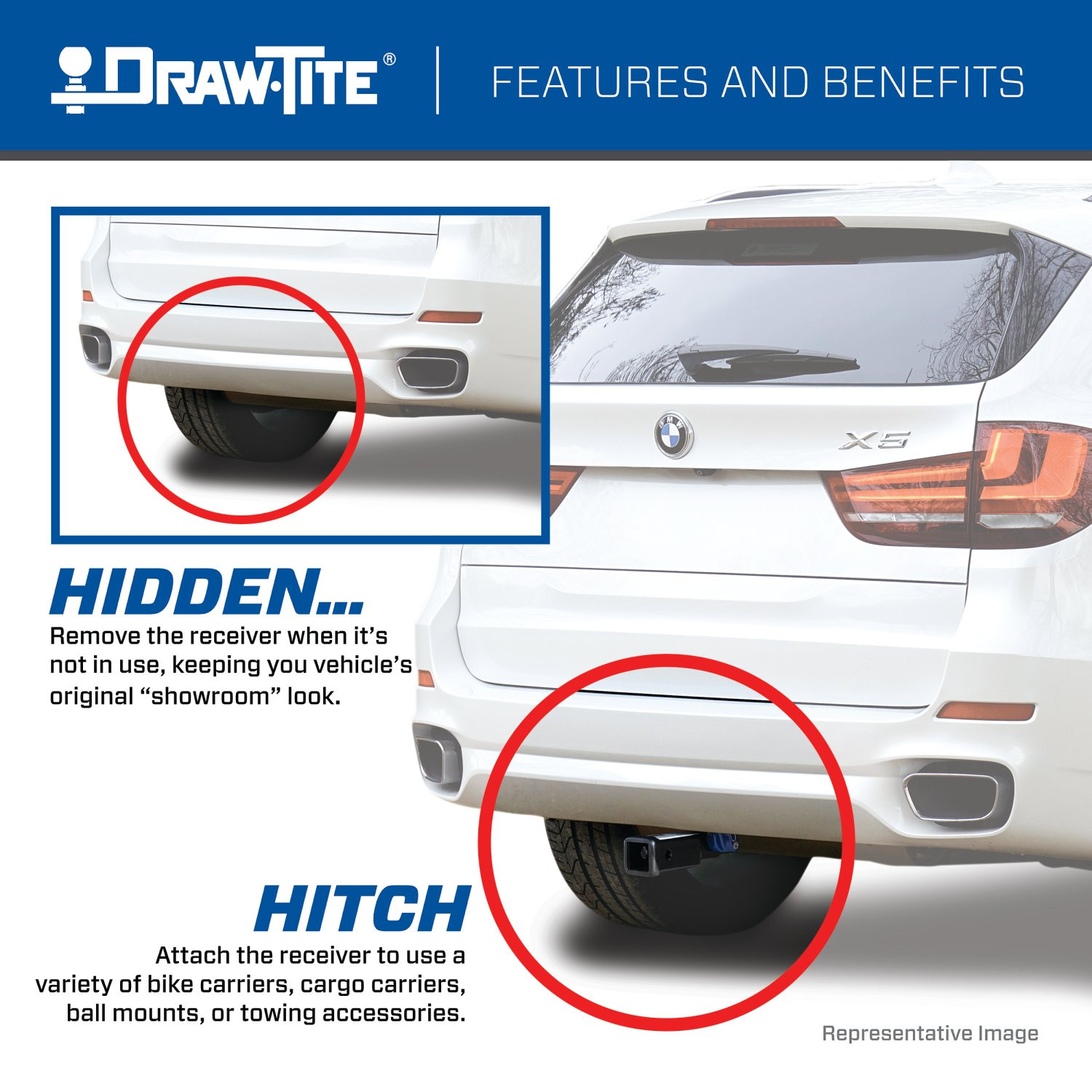
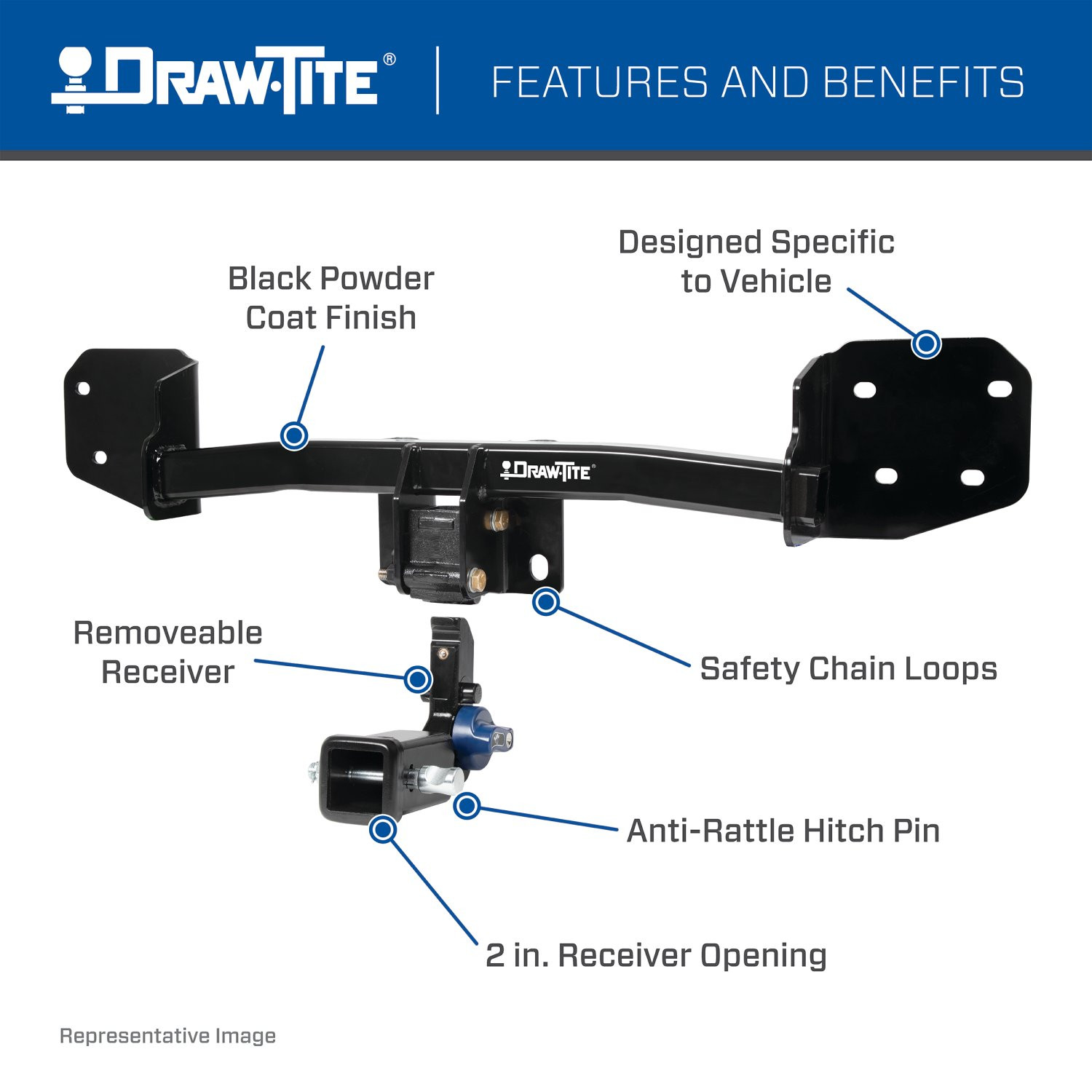
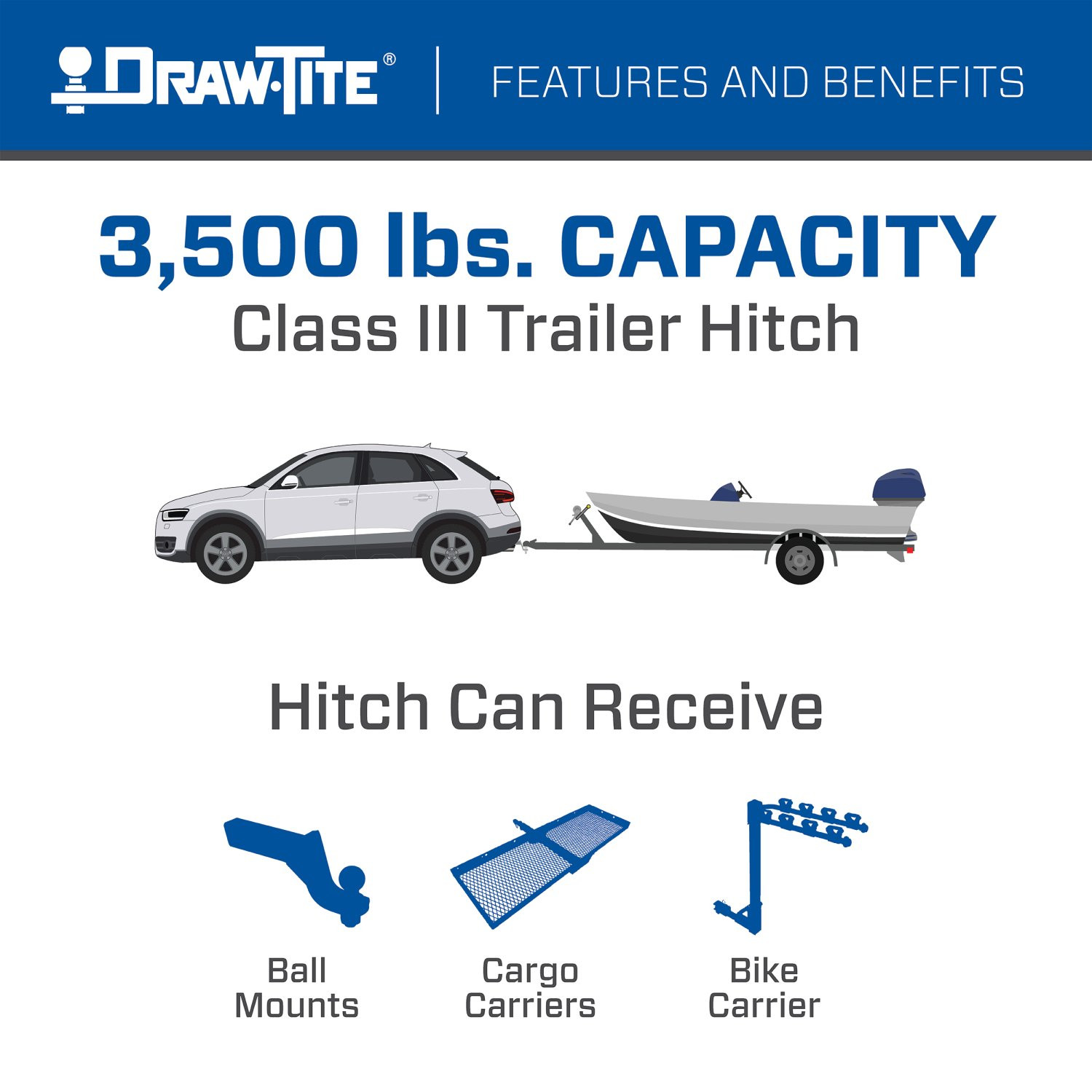
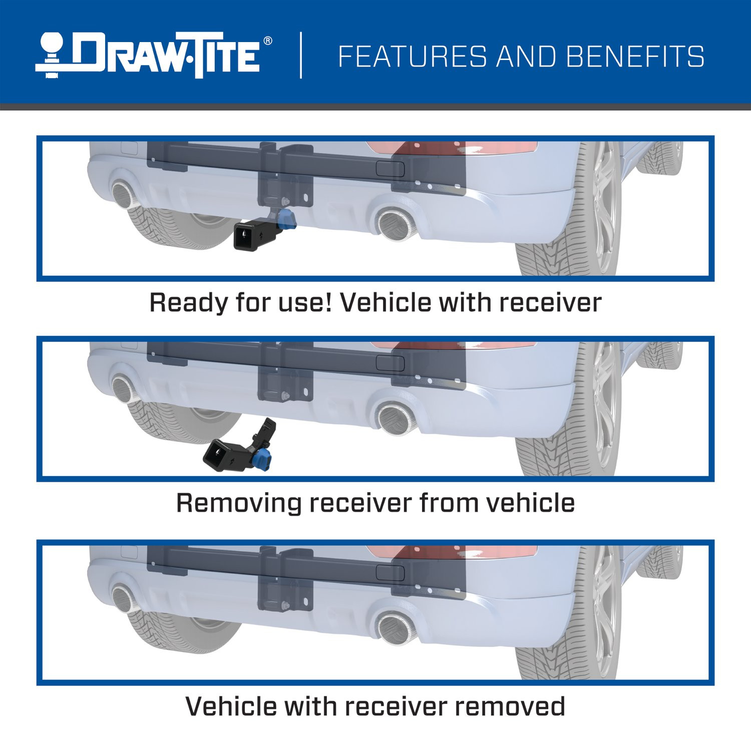
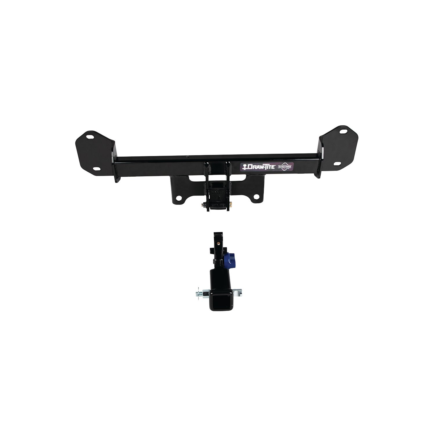
Made from welded steel with a black premium finish, the Hidden Hitch series of hitches are custom designed to ensure a superior fit for each make and model vehicle. Each Hidden Hitch is designed with a two-inch receiver opening to fit a number of different accessory attachments like bike racks, cargo carriers, and more! Draw-Tite Hidden Hitches are rated for 3,500 pounds gross trailer weight (GTW) and are best suited for use with accessories or light-duty towing. The integrated anti-theft lockable receiver ensures added safety when the hitch is in use, while the included anti-rattle hitch pin provides premium performance and security. When you are not using the Hidden Hitch, you can store the removeable receiver, anti-rattle pin, and weather covers in the hard sided carrying case that is included with your purchase.
These dependable, premium custom hitches are manufactured for 2011-2022 BMW X3 and attach to your vehicle?s frame behind the bumper for a luxuriously clean appearance. Hidden Hitch trailer hitches have a sleek black powder coat finish for superior rust and corrosion resistance and come complete with all the mounting hardware needed for installation. Plus, each hitch is tested to meet - and exceed - V-5 and SAE J684 standards and is backed by a nationwide lifetime limited warranty.
So, take that extra cooler out to the lake, hit the bike trails in the park, or hook up that utility trailer and tackle your honey-do home repairs. When you are done, remove the evidence (i.e., the removeable receiver), and go for a cruise. With the Hidden Hitch, you can do it all! Brought to you by Draw-Tite, North America?s Favorite Hitch.

Draw-Tite has designed custom-fit trailer hitches since 1946 and is one of North America's most widely fitted hitch brands. Receiver hitches use solid all-welded construction and low-profile designs that follow modern vehicle contours, install with minimal bumper cutting or drilling, meet or exceed V5 CSA and SAE J684 standards, and carry a limited lifetime warranty.
Draw-Tite has been leading custom-fit trailer hitch design and engineering since its founding in 1946, and it remains one of the most widely fitted hitch brands in North America. The company's stated approach is straightforward: every hitch is tested rigorously so that it performs well beyond published industry standards, a philosophy it markets as Tested Tough. It sits within the Horizon Global towing group alongside Reese, Fulton, Bulldog, Tekonsha, Bargman and Wesbar.
Custom fit is the defining characteristic. Rather than adapting a universal design, Draw-Tite engineers a trailer hitch for a specific make, model and model year, so it bolts to existing frame locations with minimal bumper cutting or drilling. Low-profile designs follow the rear contours and aerodynamic styling of modern vehicles, which matters more than it once did now that rear fascias are shaped and sensor-equipped. Construction is solid all-welded steel for maximum strength, and every hitch meets or exceeds V5 CSA and SAE J684 standards and is backed by a nationwide limited lifetime warranty.
The range spans receiver sizes and classes to suit different loads, from 1-1/4 inch receivers for bike racks, cargo carriers and light trailers up through 2 inch receivers for heavier towing. Front mount hitches add a receiver at the front of the vehicle for winch mounts, snow plows, spare carriers and precise trailer positioning.
The Hidden Hitch series takes concealment further by mounting behind the vehicle's rear fascia, so the vehicle keeps its factory appearance until a removable receiver is fitted. Each is custom designed per make and model for a no-drill installation that does not compromise ground clearance, rated for up to 3,500 pounds gross trailer weight and 350 pounds tongue weight. Matching plug-and-play wiring completes the towing system.
Experts available to answer your questions
Call 888-634-94941 compatible vehicles
| Year | Make & Model | Notes |
|---|---|---|
| 2022 - 2024 | BMW X3 | — |
The 2022-2024 BMW X3 Draw-Tite Hidden Hitch Completely Hidden Trailer Hitch 2 Inch Removable Receiver Bundle w/ Plug-n-Play T-One Wiring Harness (Part #DTB76906-118879) fits the following vehicles: 2022-2024 BMW X3. Always verify your specific year, make, and model before ordering.
Yes, the 2022-2024 BMW X3 Draw-Tite Hidden Hitch Completely Hidden Trailer Hitch 2 Inch Removable Receiver Bundle w/ Plug-n-Play T-One Wiring Harness (Part #DTB76906-118879) is designed to fit the 2022-2024 BMW X3.
The 2022-2024 BMW X3 Draw-Tite Hidden Hitch Completely Hidden Trailer Hitch 2 Inch Removable Receiver Bundle w/ Plug-n-Play T-One Wiring Harness (Part #DTB76906-118879) fits 2022-2024 BMW X3 models. The 2024 model year is the last year covered by this part number. For newer models, check for an updated version.
The 2022-2024 BMW X3 Draw-Tite Hidden Hitch Completely Hidden Trailer Hitch 2 Inch Removable Receiver Bundle w/ Plug-n-Play T-One Wiring Harness (Part #DTB76906-118879) Refer to the included instructions for installation details. Basic hand tools are typically all you need.
Yes, part number 76906 is designed for BMW X3 and BMW X4 models. However, the manual directs you to visit the Horizon Global website for the most up-to-date information regarding specific application years, sub-models, and trim levels, as compatibility may vary.
The 76906 is a weight-carrying hitch with a maximum Gross Trailer Weight (GTW) of 3500 lb (1589 kg) and a maximum tongue weight of 350 lb (159 kg). Weight-distributing capacity is listed as N/A. Never exceed your vehicle manufacturer's recommended towing capacity or these hitch capacities.
Required tools include: ratchet, torque wrench, safety glasses, sockets (8mm, 10mm, 13mm, 18mm), socket extension, tape measure, utility knife, flat head screwdriver, marker, plastic trim tools, drill, 1/8 inch drill bit, plastic rivet gun, silicone sealant, blue thread locker, and T20 star drivers. A deep well socket is required for the 18mm socket. The manual lists these as 'Equipment Required.'
Yes, drilling is required. You must use a 1/8 inch drill bit to drill out the center of plastic rivets holding the wheel well trim. For X3 models, you will drill out 4 rearmost plastic rivets; for X4 models, you will drill out 3 plastic rivets. After drilling, use a trim panel tool to remove the remaining rivet heads.
Trimming is required on X4 models only. You must trim the fascia in a specific area using a tape measure, marker, and utility knife. The trim dimensions are 4.25 inches by 13.50 inches, with a measurement of 2.125 inches from the center of a screw and 1.50 inches. Additionally, for X3 models, you must cut a notch in the underbody panel. For X4 models, you must trim a sensor bracket in the area shown in Figure 13 (13.50 inches by 4.75 inches). The manual notes that the vehicle requires trimming and you must obtain the vehicle owner's permission before installation.
All M12 hex flange nuts holding the bumper beam to the end panel must be tightened to 68 lb-ft (92 N·m) using a torque wrench. The exhaust hanger hex flange nuts must be tightened separately to 25 lb-ft (34 N·m). Proper torque is needed to keep the hitch secure to the vehicle when towing.
Each of the two fastener assemblies (M12 bolt, flat washer, and prevailing torque nut) attaching the receiver housing to the hitch must be torqued to 92 lb-ft (125 N·m).
The installation sequence is: (1) Remove taillights; (2) Remove underbody panel (X3 models only); (3) Remove fascia; (4) Remove bumper beam; (5) Install hitch and bumper beam with blue thread locker and foam gasket; (6) Tighten all fasteners to specification using a torque wrench; (7) Trim fascia (X4 models only); (8) Reinstall fascia; (9) Reinstall wheel well trim with plastic rivets; (10) Reinstall taillights; (11) Trim and reinstall underbody panel. The manual emphasizes that this is an expert-level installation.
Yes, the bumper beam must be removed. For all models, use an 18mm deep well socket with a 6 inch extension to remove the 4 hex flange nuts holding the bumper beam to the end panel (2 per side). For X3 models, also disconnect the sensor wiring and plastic rivet. For X4 and X3 2018-current models, also remove 2 hex nuts holding exhaust hanger brackets using a 13mm socket. The bumper beam is then reinstalled after the hitch is positioned.
Key differences include: (1) X3 models require removal of an underbody panel; X4 models do not. (2) X4 models require fascia trimming; X3 models do not. (3) Taillight removal differs: X3 models use a 10mm socket to remove hex nuts; X4 and X3 2018-current models access taillights from inside the cargo area. (4) X4 models have different sensor bracket and wire routing requirements. (5) Underbody panel notch dimensions differ between X3 2011-2017 and X3 2018-current models. (6) Foam gasket handling differs: X3 2011-2017 models remove it; X3 2018-current and X4 models keep it. Consult the specific figures and steps for your model year.
Yes, blue thread locker must be applied to all studs on the vehicle end panel before installing the hitch and bumper beam. This is a required step in the installation process.
Silicone sealant is required in specific circumstances but is not provided with the hitch. For X4 models and X3 2011-2017 models, apply silicone sealant to hitch bracket mounting surfaces. For X3 2018-current models, apply silicone sealant only if the foam gasket is damaged. The sealant is applied between the hitch and aluminum bumper beam.
Fastener Kit 76906F includes: (2) Hex Bolts M12-1.75 x 100mm CL10.9, (2) Flat Washers 7/16 inch, (2) Flange locknuts M12-1.75 CL10, (8) Plastic Rivets, and (4) Cable ties. Fastener Kit 76906F2 includes: (1) Warning Card and (2) Warning Labels. The installation also reuses existing factory M12 hex flange nuts from the vehicle.
Yes, the existing factory M12 hex flange nuts holding the bumper beam to the end panel are reused during installation. These fasteners are loosely reinstalled in Step 5 and then tightened to specification in Step 6. The exhaust hanger hex nuts removed in Step 4 are also reattached in Step 5.
The foam gasket is a factory component located between the aluminum bumper beam and the end panel. For X3 2011-2017 models, remove the foam gasket completely. For X3 2018-current models, keep the foam gasket on the end panel; if damaged, apply silicone sealant to hitch bracket mounting surfaces. For X4 models, leave the foam gasket between the bumper and end panel attached to studs. In all cases where the hitch is installed, place the foam gasket between the hitch and aluminum bumper beam.
To install the receiver housing: (1) Remove the receiver assembly from the case. (2) Remove the receiver from the receiver housing by using the key to unlock the blue knob, pushing it in, and rotating clockwise until you hear a click. (3) Install the weather covers to the top and bottom of the receiver housing. (4) Attach the receiver housing to the hitch by inserting it between the hitch brackets, aligning with holes, and inserting 2 fastener assemblies (M12 bolt, flat washer, and prevailing torque nut). (5) Torque each fastener to 92 lb-ft (125 N·m). For receiver installation and use details, refer to instruction 76900N.
Keep the warning card in the vehicle glove compartment for future reference. Apply one label to the top of the receiver and one label to the vehicle door jamb. These materials are included in Fastener Kit 76906F2.
Always wear safety glasses when installing the hitch. Observe safety precautions when working beneath a vehicle. Do not cut access or attachment holes with a torch. The sensor wire on X4 models must not be cut. If the hitch is removed, plug all holes in the trunk pan or other body panels to prevent entry of water and exhaust fumes. A damaged hitch or ball should be removed and replaced immediately.
After installation, check that all fasteners are tight and the hitch is securely mounted to the vehicle. Regularly check that all fasteners remain tight and the hitch is securely mounted during vehicle use. Proper torque is needed to keep the hitch secure to the vehicle when towing. If the hitch is removed at any time, plug all holes in the trunk pan or other body panels to prevent entry of water and exhaust fumes.
The manual states you should regularly check that all fasteners are tight and the hitch is securely mounted to the vehicle. No specific interval is provided, but regular inspection is emphasized as important for safe towing.
No. The manual explicitly states: DO NOT cut, weld, or modify this trailer hitch. Doing so will compromise the hitch integrity and safety.
The manual does not address spare tire interference. However, the installation does involve working with exhaust hanger brackets. For X4 and X3 2018-current models, you must remove 2 hex nuts holding exhaust hanger brackets to the bottom of the bumper beam, then reattach them after the hitch is installed. For specific interference concerns with your vehicle, consult the Horizon Global website or contact technical support at 800-632-3290.
The manual addresses sensor wiring on X3 and X4 models. For X3 models, you must disconnect the sensor wiring and plastic rivet attached to the bumper beam. For X4 models, you must remove plastic rivets holding the sensor bracket to the bumper, detach the sensor wire from clips, and secure the sensor wire in 4 places using cable ties as shown in Figure 13. The sensor wire must not be cut. After installation, all wiring harnesses must be reconnected. Consult the Horizon Global website or technical support if you have concerns about specific sensor compatibility.
The installation difficulty is rated as 'Expert.' This rating is based on the time and effort involved, which may vary depending on installer level of expertise, condition of the vehicle, and availability of proper tools and equipment. The installation requires drilling, trimming, removal of multiple trim panels and the bumper beam, and precise torque specifications.
The manual provides ball mount selection criteria but does not specify which ball mounts are included or sold separately. The rise must be between 0.75 inches (minimum) and 10.5 inches (maximum). The distance from the center of the ball hole to the center of the pin hole is the length. For safety chain attachments, quick links are available separately: #49131 (5/16 inch, Max GTW 3,500) and #44133 (3/8 inch, Max GTW 3,500). Consult the Horizon Global website or contact technical support for specific ball mount recommendations for your application.
Yes, part 76906 is designed for BMW X3 and X4 models. Visit the Horizon Global website for the most up-to-date information on specific years, sub-models, and trim levels.
Maximum Gross Trailer Weight: 3500 lb (1589 kg). Maximum tongue weight: 350 lb (159 kg). Never exceed your vehicle manufacturer's recommended towing capacity.
Yes. You must drill out plastic rivets holding the wheel well trim using a 1/8 inch drill bit (4 rivets for X3 models, 3 for X4 models).
Yes. X4 models require fascia trimming (4.25 inches by 13.50 inches). All X3 models require underbody panel notch cutting. X4 models also require sensor bracket trimming. The manual notes the vehicle requires trimming and you must obtain the vehicle owner's permission.
M12 hex flange nuts: 68 lb-ft (92 N·m). Exhaust hanger nuts: 25 lb-ft (34 N·m). Receiver housing fasteners: 92 lb-ft (125 N·m). Use a torque wrench for all fasteners.
Yes. Use an 18mm deep well socket with a 6 inch extension to remove 4 hex flange nuts (2 per side) holding the bumper beam to the end panel. The bumper is reinstalled after the hitch is positioned.
Always wear safety glasses. Do not cut access holes with a torch. Do not cut the sensor wire. Observe safety precautions when working beneath the vehicle. Plug all holes if the hitch is removed to prevent water and exhaust fumes from entering the vehicle.
Verify all fasteners are tight and the hitch is securely mounted. Regularly check fastener tightness during use. Proper torque is essential for safe towing.
Tighten all fasteners immediately using the correct torque specifications: M12 hex flange nuts to 68 lb-ft (92 N·m), exhaust hanger nuts to 25 lb-ft (34 N·m), and receiver housing fasteners to 92 lb-ft (125 N·m). The manual emphasizes regularly checking that all fasteners are tight and the hitch is securely mounted to the vehicle. Loose fasteners compromise hitch safety during towing.
If the foam gasket is damaged during removal or installation, apply silicone sealant (not provided) to the hitch bracket mounting surfaces. This applies to X4 models and X3 2018-current models. For X3 2011-2017 models, the foam gasket is removed entirely, so damage is not a concern. Silicone sealant helps prevent water and exhaust fumes from entering the vehicle through the mounting area.
The manual explicitly warns: Sensor wire. DO NOT CUT! If the sensor wire is cut, the rear sensor system will not function properly. Do not proceed with installation. Contact Horizon Global technical support at 800-632-3290 or TechnicalSupport@horizonglobal.com for guidance on sensor wire repair or replacement before completing the installation.
A hitch or ball which has been damaged should be removed and replaced immediately. Do not use the hitch for towing if it is damaged. Contact Horizon Global at 47912 Halyard Drive, Suite 100, Plymouth, MI 48170, 1-800-632-3290, or visit www.horizonglobal.com for replacement parts and warranty claim information.
If the hitch is removed, plug all holes in the trunk pan or other body panels to prevent entry of water and exhaust fumes. This is important to protect the vehicle's interior and prevent corrosion or damage from moisture and exhaust gases.
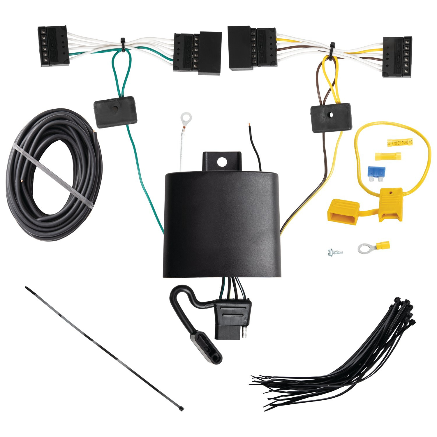
The T-One® Connector (part number 118879-037) is a vehicle wiring connector system that integrates with your vehicle's tail light wiring to enable trailer lighting control. It consists of a black box module, wiring harnesses with colour-coded wires (yellow, green, white, and black), and a 4-Flat connector for trailer use. The system allows your vehicle to communicate lighting signals to a connected trailer.
You will need: Trim Panel Remover, #2 Philips Screwdriver, Flat Screwdriver, 10mm Socket or wrench, Drill with 3/32" Drill Bit, Wire Crimpers, Wire Cutters, and Test-probe. These tools are required to remove panels, disconnect wiring, drill if needed, crimp connections, and test the installation.
The kit includes: a black box module, colour-coded wiring harnesses (yellow, green, white, and black wires), double-sided tape for mounting the black box, cable ties for securing the harness, yellow butt connectors for wire connections, a yellow fuse holder with a 15 amp fuse, and ring terminals. A 4-Flat connector is also included for storage in the rear cargo area when not in use.
Yes. You must disconnect the vehicle's Negative (−) battery cable before making power connections. This is done in Step 11 before connecting the fuse holder to the positive battery cable. The negative cable is reconnected in Step 12 after all power connections are complete.
You must remove: the privacy screen (if installed), rear side cargo panels from both driver's and passenger's sides, cargo floor covering, and any trim panels required to access the driver's side trim panel opening where the black box module will be mounted. The felt liner covering the battery compartment must also be removed. Take care not to break locking tabs on cargo panels during removal.
The black box module is mounted on the driver's side behind the trim panel opening using the double-sided tape provided in the hardware kit. The remainder of the harness is secured with cable ties to prevent damage or rattling, taking care to avoid areas that could cut or pinch the wire.
1. On the driver's side, insert the T-One® Connector end with the yellow wire between the mating vehicle wiring connectors and lock into place, ensuring locking tabs are fully engaged. 2. On the passenger's side, insert the T-One® Connector end with the green wire between the mating vehicle wiring connectors and lock into place. Both connections must be fully inserted with locking tabs secure to avoid damage.
The harness contains four wires: Yellow wire (driver's side tail light connection), Green wire (passenger's side tail light connection), Black 12 ga. wire (12-volt power connection to the positive battery terminal via the fuse holder), and White 14 ga. wire (ground connection to the negative battery terminal). Each wire has a specific routing and connection point as detailed in the installation steps.
The black 12 ga. power wire is routed from the T-One® black box to the battery compartment. It is connected to the black power wire on the black box using a yellow butt connector (provided). The wire then connects to the positive (+) battery cable through a fuse holder with a 15 amp fuse. The fuse holder is attached to the positive battery cable using a ring terminal after the fuse holder wire is cut.
The white 14 ga. ground wire is routed from the T-One® black box under the driver's side metal cargo rails to the battery compartment. It is connected to the negative (−) battery terminal using a ring terminal and a 10mm socket or wrench. This connection must be made after the negative battery cable is reconnected.
A 15 amp fuse is used. It is installed in the yellow fuse holder provided in the hardware kit. The fuse holder is connected between the black 12 ga. power wire and the vehicle's positive (+) battery cable. The fuse is installed in Step 13 after all other connections are complete.
Route the green wire end through the opening and under the metal cargo hook rails, along the vehicle's battery, and up through the opening under the passenger's cargo rail. Route the white 14 ga. ground wire and black 12 ga. power wire under the driver's side metal cargo rails to the battery compartment. Avoid routing wires through hot pipes, heat shields, the fuel tank, or any other points that may pinch or break the wire. Use cable ties to secure the harness and prevent rattling.
Always wear safety glasses during installation. Read and follow all warnings and cautions printed on the vehicle's battery before making electrical connections. Do not exceed the lower of the towing manufacturer's rating (including in your vehicle owner's manual) or the specific amperage ratings stated on the product. Avoid pinching or cutting wires when reinstalling trim panels. Do not damage locking tabs on connectors. All connections must be complete for the T-One® Connector to function properly.
Test and verify the installation with a test light or trailer once installed. For the initial test, reset the vehicle electrical system by temporarily removing the key from the ignition. Use a test-probe (included in required tools) to verify proper connections. Ensure all connections are complete and secure before testing.
Reinstall all plastic trim panels, floor covering, and other items that were removed during installation, being careful not to pinch or cut the wires. Verify that all connections are secure and complete. Test the installation with a test light or trailer. Reset the vehicle electrical system by temporarily removing the ignition key for the initial test. Store the 4-Flat connector in the rear cargo area when not in use.
The manual does not specify a maximum amperage rating for the product itself. However, you must not exceed the lower of: the towing manufacturer's rating (including the rating in your vehicle owner's manual) or the specific amperage ratings stated on the product. A 15 amp fuse is installed as part of the system. Refer to your vehicle owner's manual and the product documentation for specific amperage limits.
Yes, disconnect the Negative (−) battery cable before making power connections in Step 11. Reconnect it after all power connections are complete in Step 12.
A 15 amp fuse is installed in the yellow fuse holder provided. It protects the black 12 ga. power wire connection to the vehicle's positive battery terminal.
Do not exceed the lower of the towing manufacturer's rating or the specific amperage ratings stated on the product. Overloading circuits can cause fires. Wear safety glasses during installation and avoid routing wires through hot pipes, heat shields, or the fuel tank.
Verify that all connections are complete and secure. Check that the 15 amp fuse is installed in the fuse holder. Ensure the black power wire is connected to the positive battery terminal and the white ground wire is connected to the negative battery terminal. Test the installation with a test light or trailer. Reset the vehicle electrical system by temporarily removing the ignition key. If the system still does not function, verify that the yellow and green connector ends are fully inserted into the vehicle tail light connectors with locking tabs engaged.
Ensure you are inserting the connector ends fully between the mating vehicle wiring connectors. The locking tabs must engage completely. Be careful not to damage the locking tabs during insertion. If the tabs are damaged, the connectors will not lock properly and the system will not function. Do not force the connectors; they should slide in smoothly until the locking tabs engage.
On Sale Today
Original price was $780.00. Current price is $699.18.You save $80.82 (10%)
Free Shipping
Ships free on all orders
 Authorized Dealer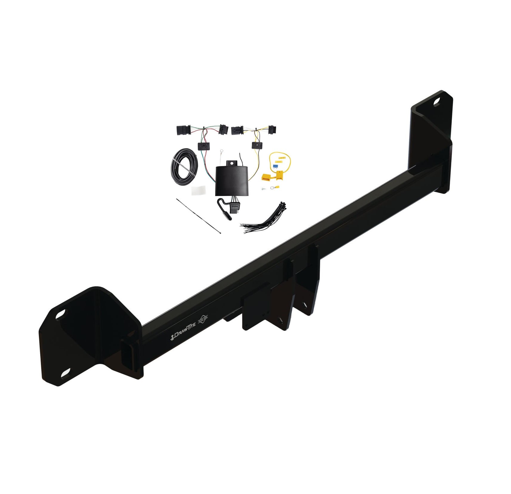


FREE ShippingFREE SHIPPING
Estimated delivery Mon, Sep 7 - Thu, Sep 10
Order before 2 PM EST Monday–Friday for same-day processing
Guaranteed safe & secure checkout
No reviews have been added for this product.