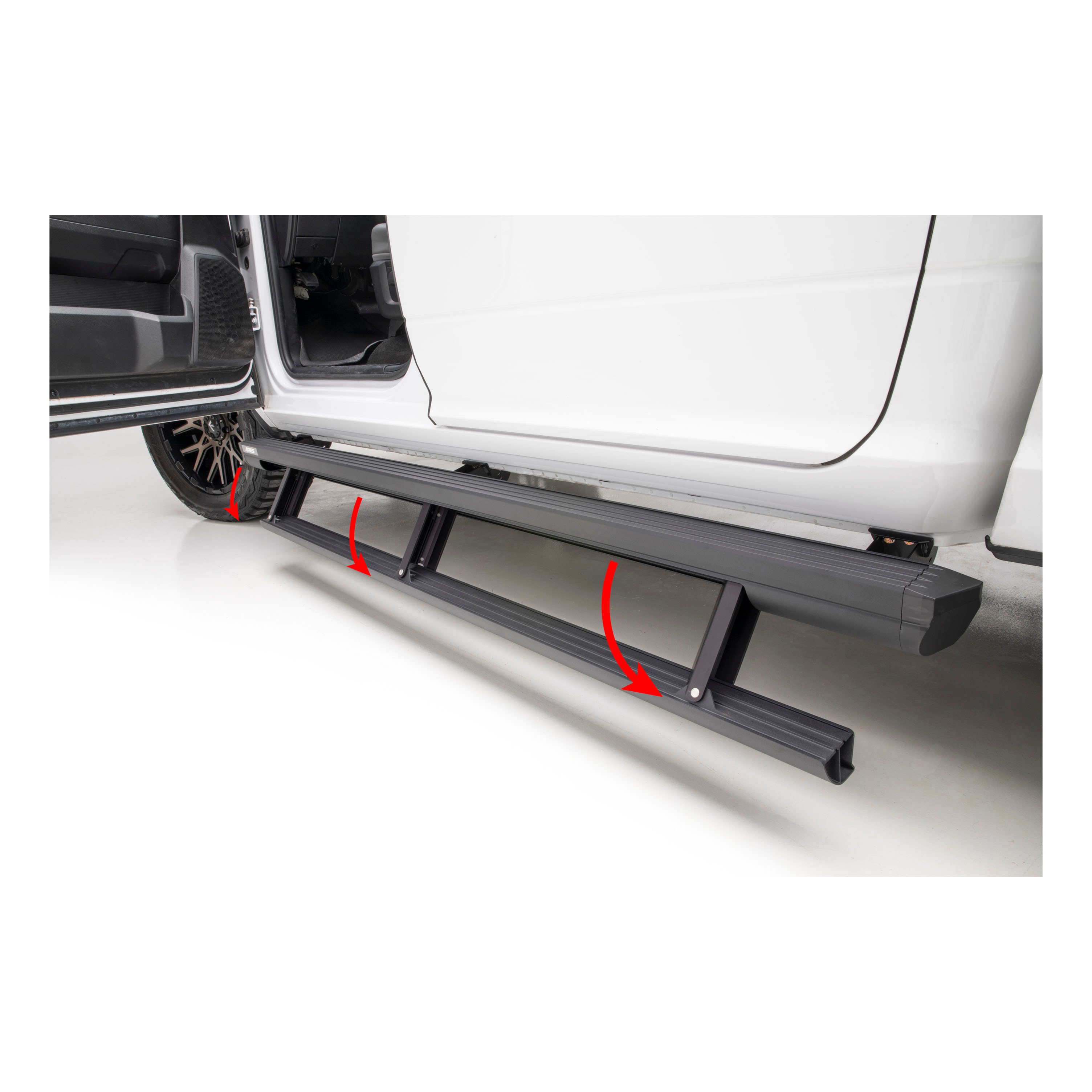
ARIES ActionTrac 87.6" Powered Running Boards, Select Ram 1500 Crew Cab Step Nerf Bar KitARIESOriginal price was $2,634.95. Current price is $1,998.95.In Stock
View productOur in-house experts typically reply within one business day.

ARIES
Verify Fitment
Select your vehicle to confirm this part fits.



Always the correct part
We know our products
Quality Products
Free Shipping!
Always the correct part
We know our products
Quality Products
Free Shipping!
Includes one pair of running boards, mounting hardware and wiring harness
These boards are not a substitute for rocker bars
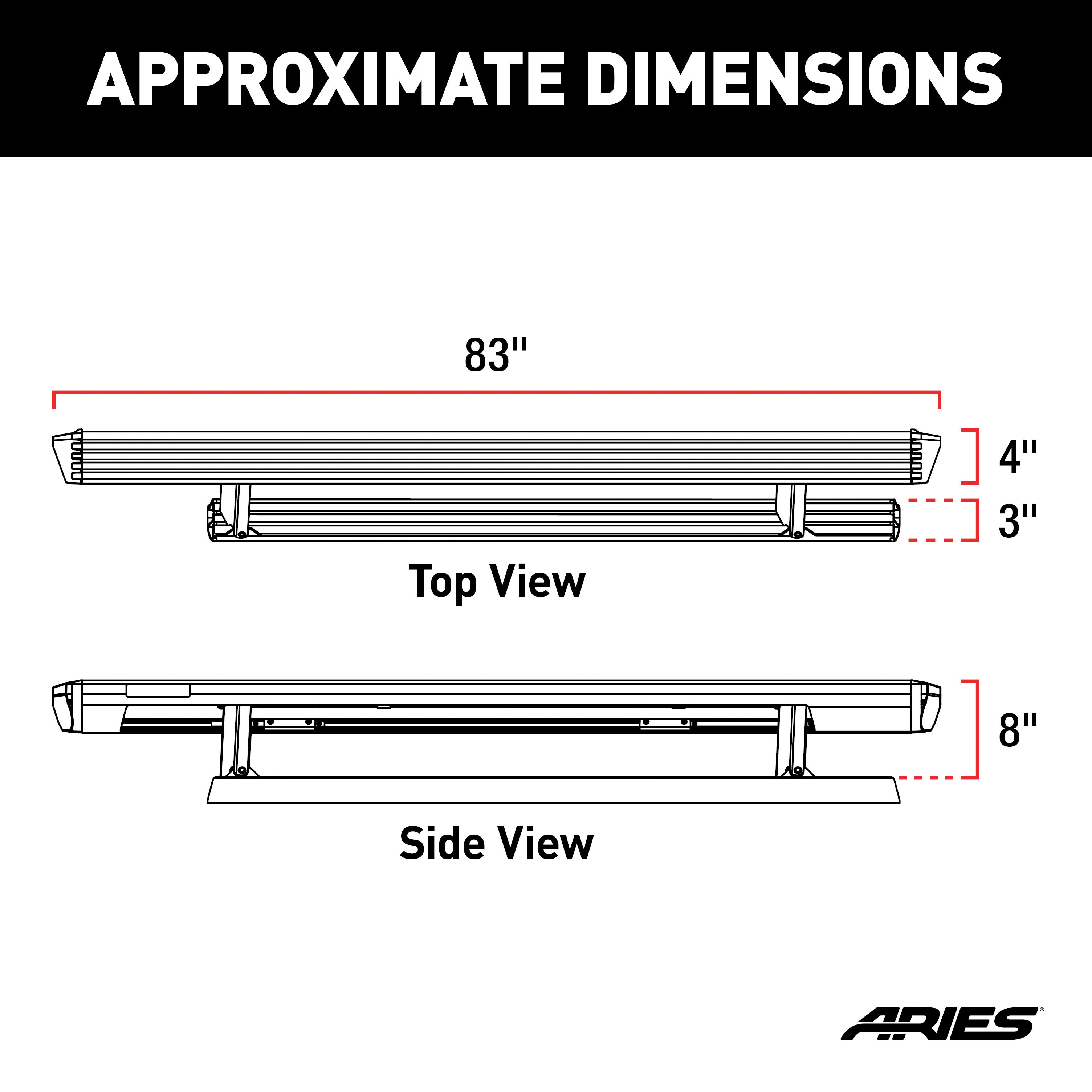
83" stepping surface, 87.6" overall length



Warranty: Limited Lifetime Warranty (Five-Year Finish, Three-Year Parts)
Finish: CARBIDE BLACK POWDER COAT
Material: Aluminum
Side Component Type: Board and Bracket
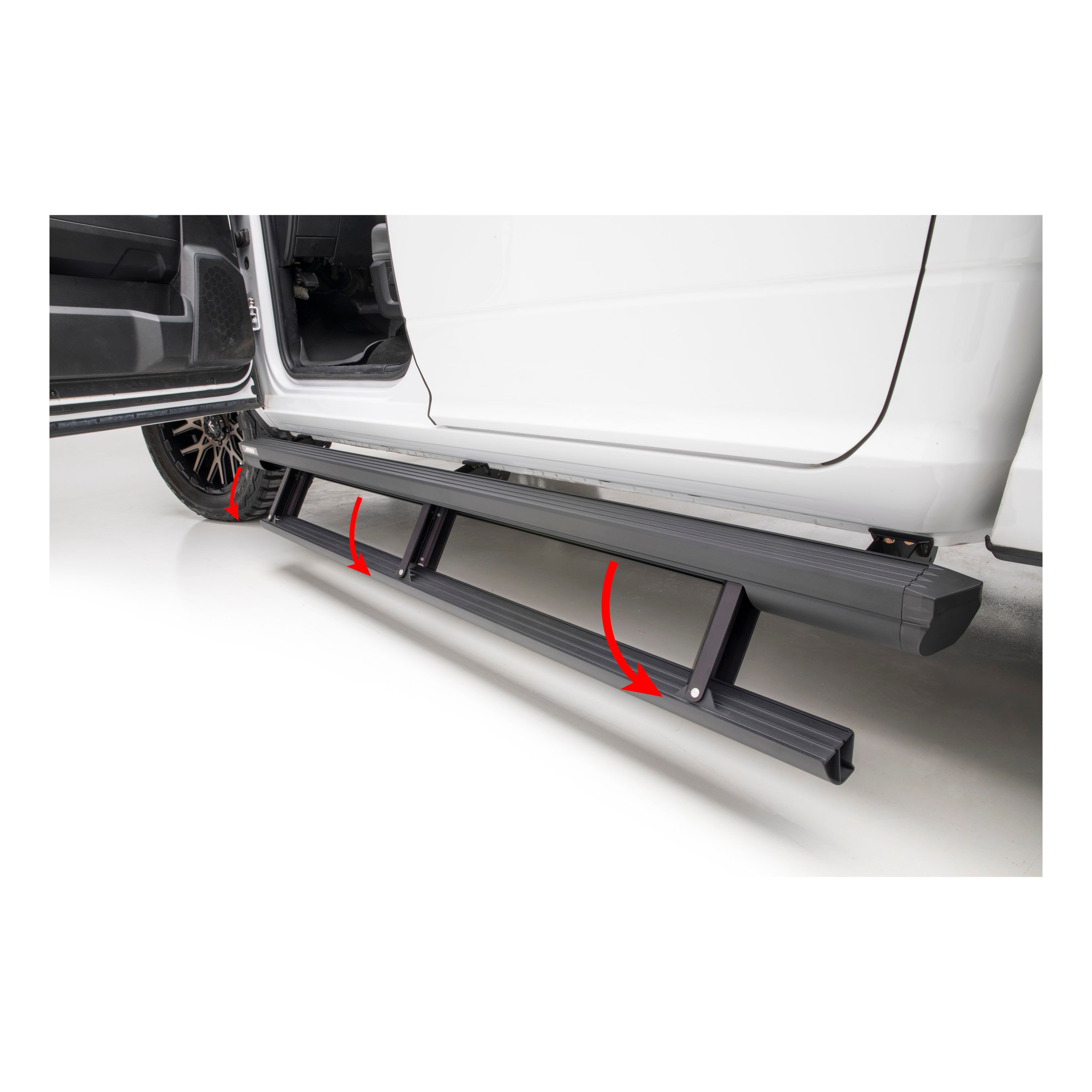
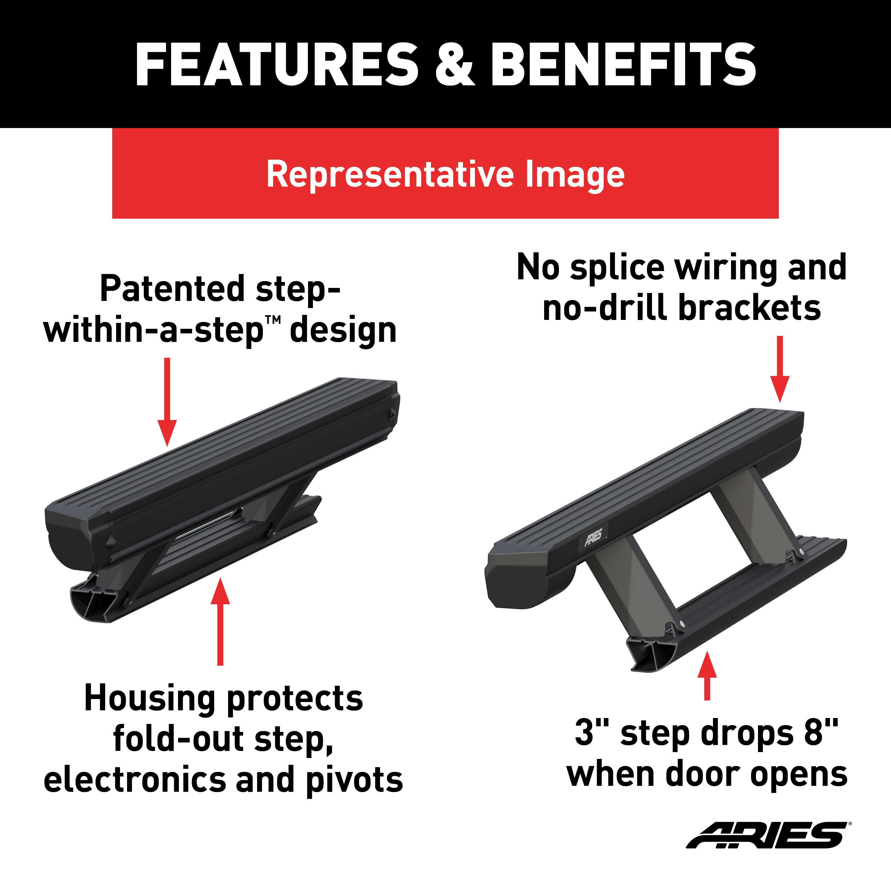
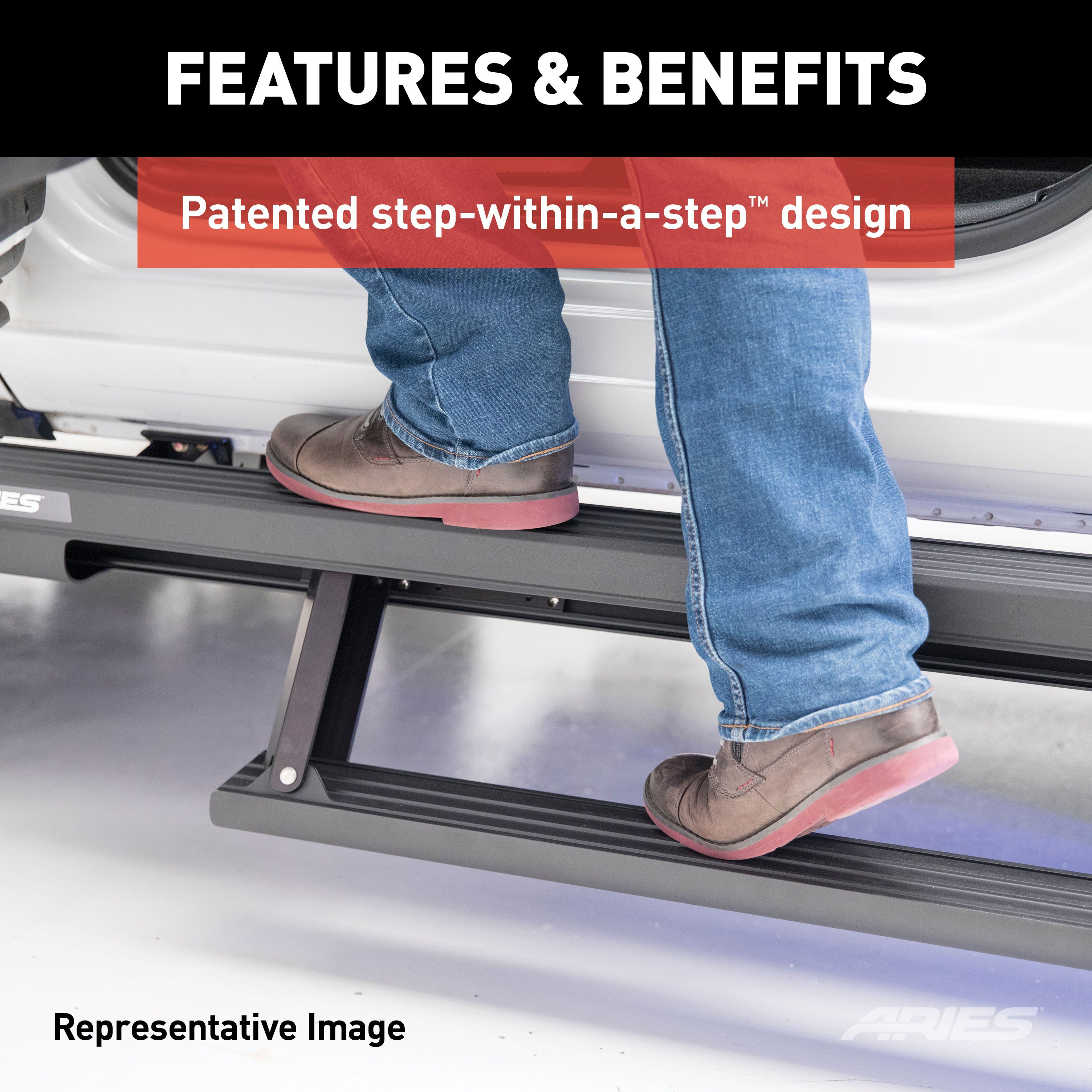
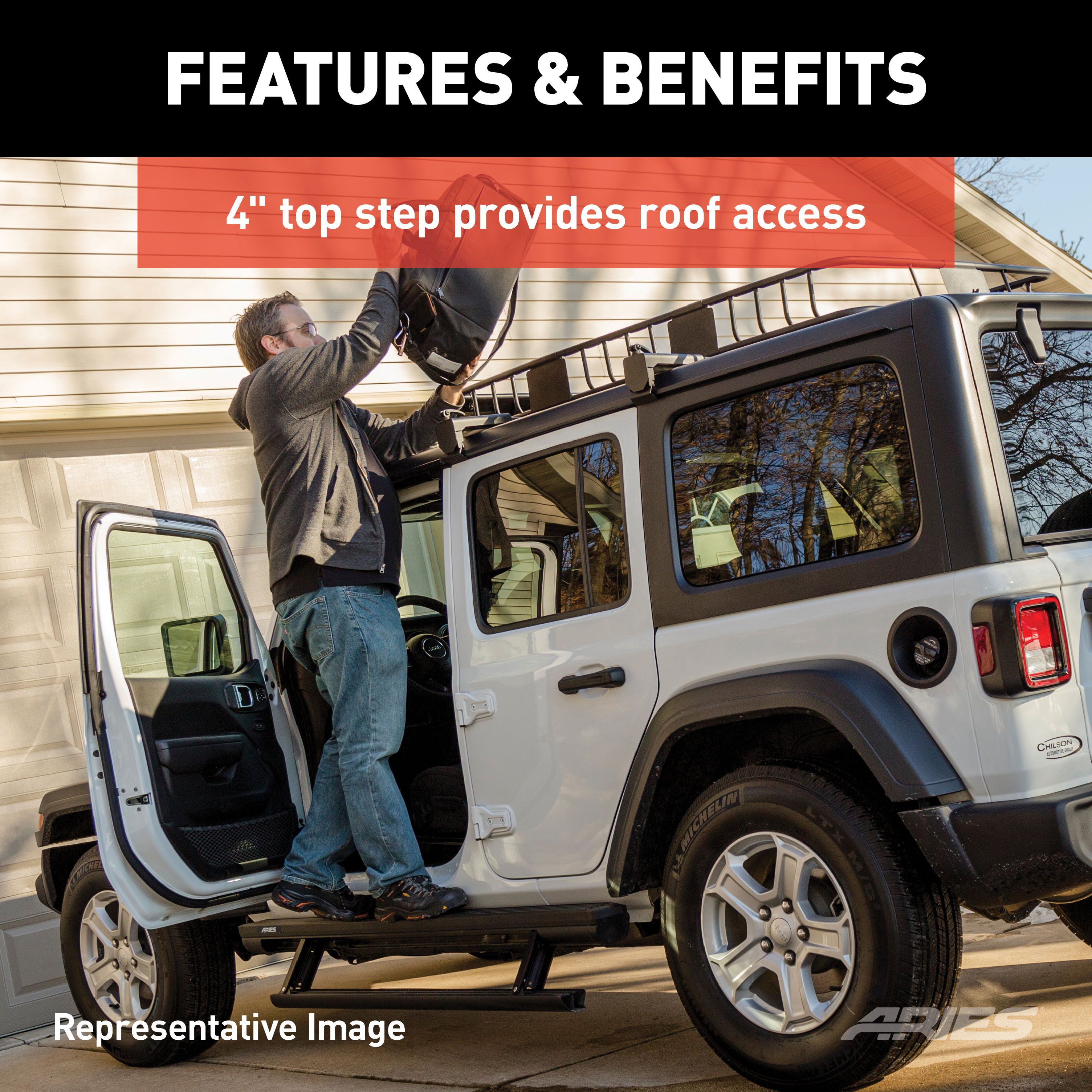
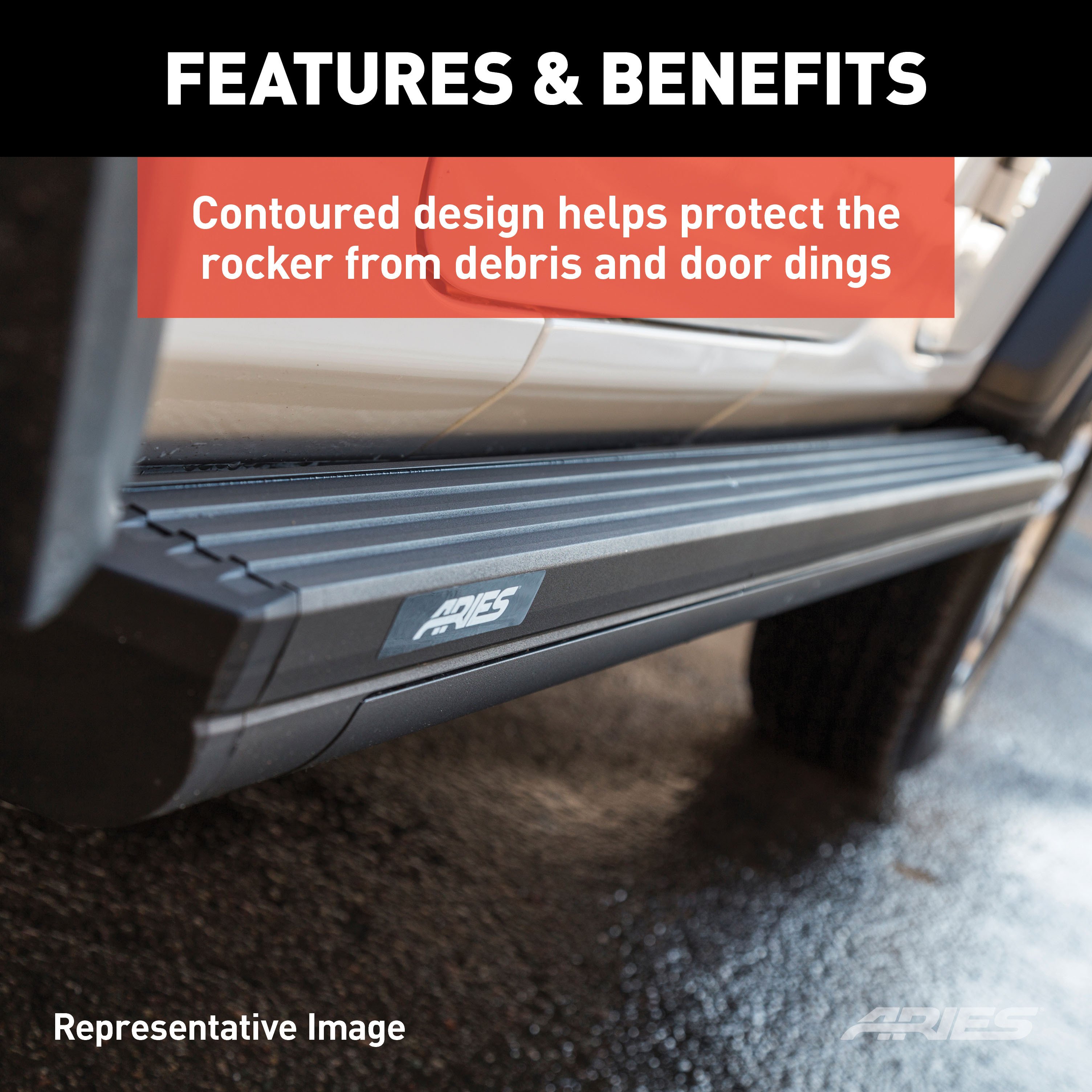
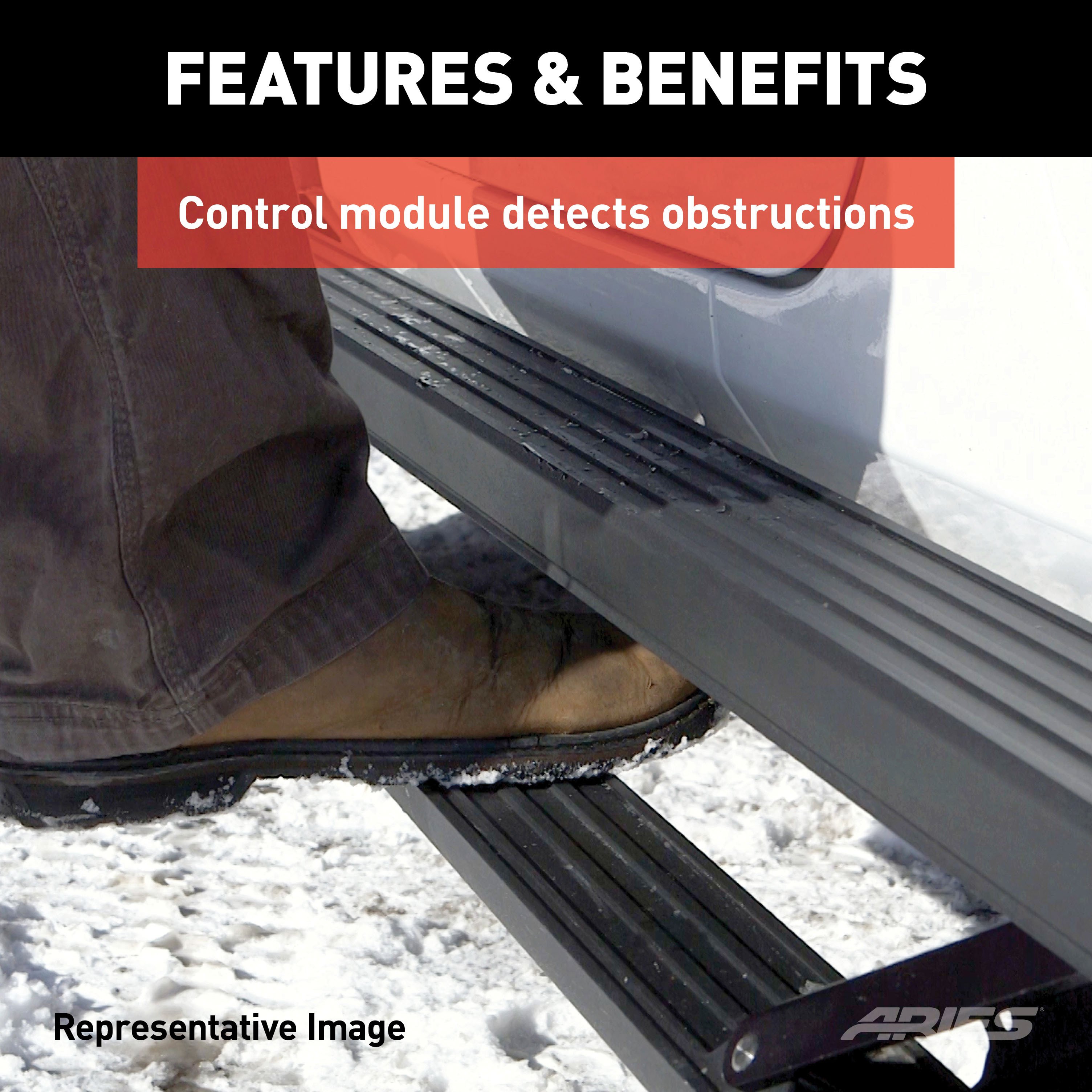
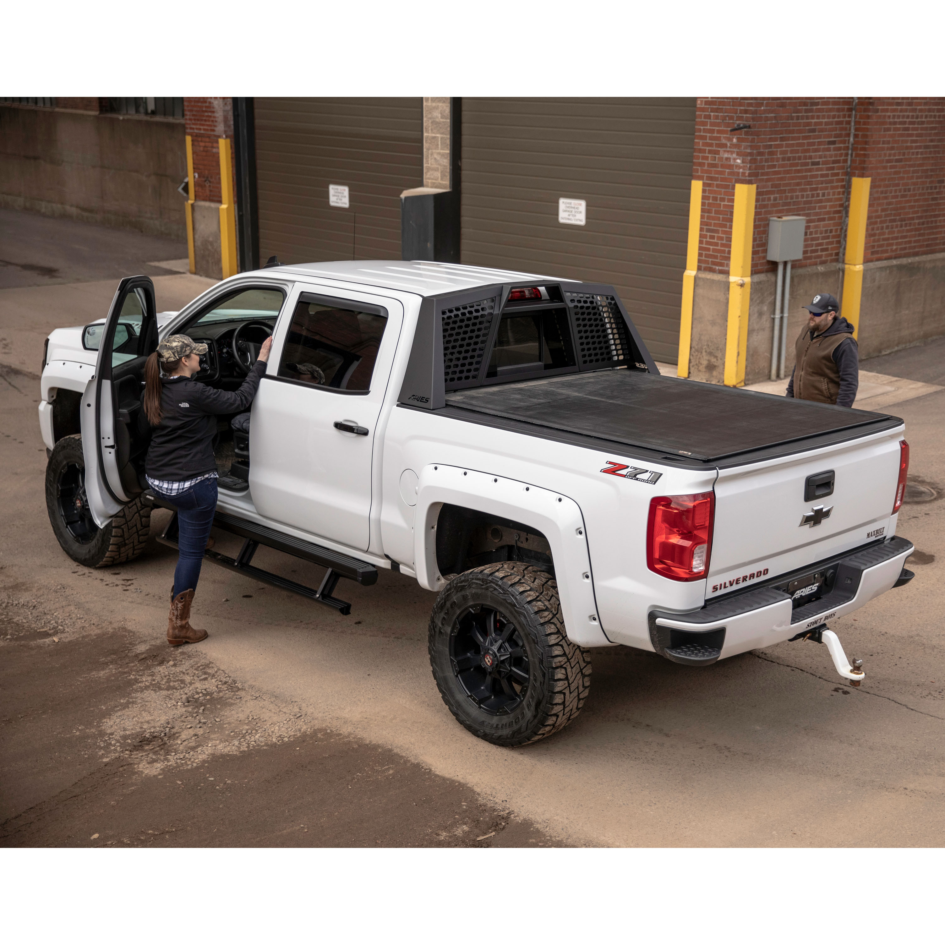
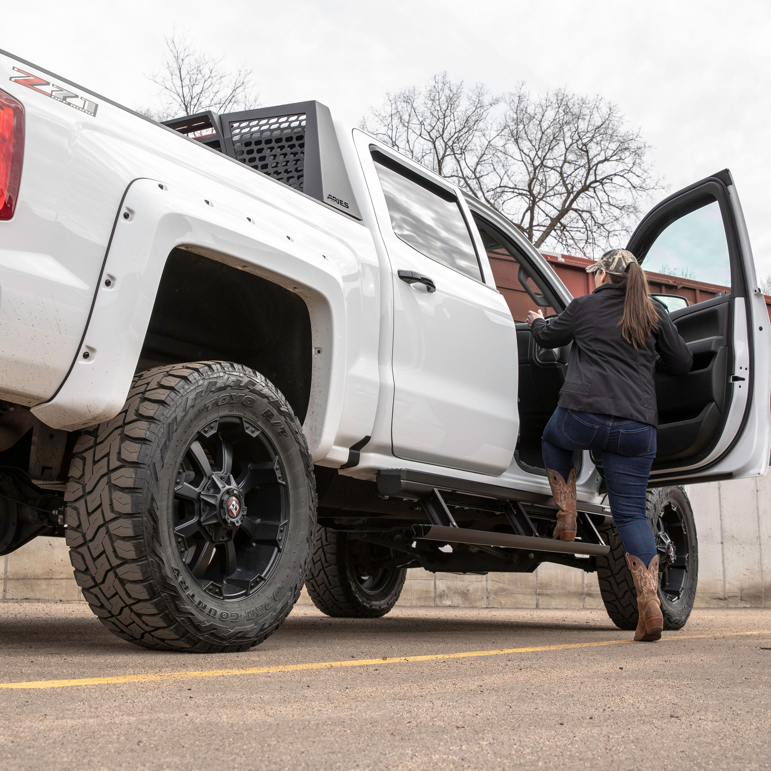
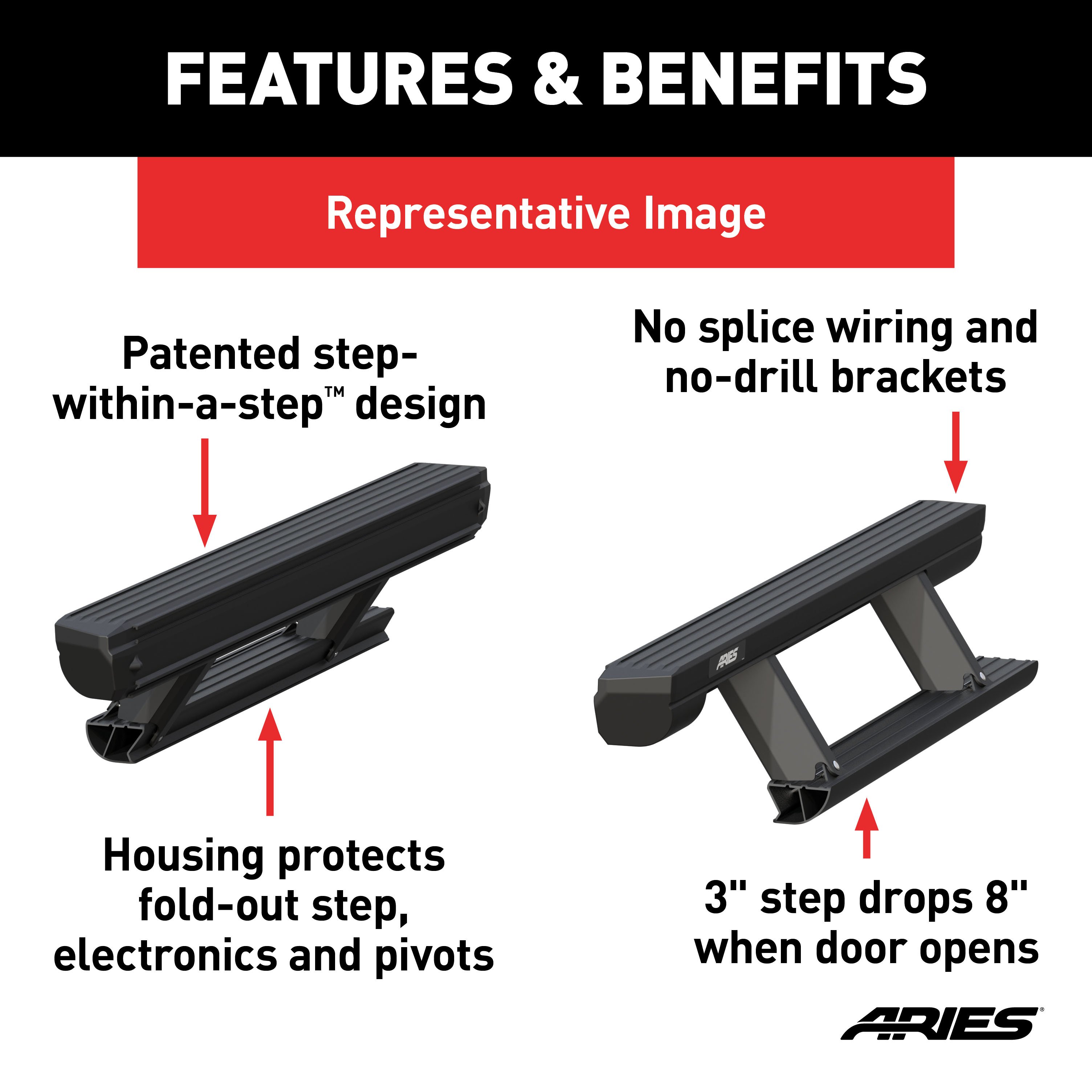
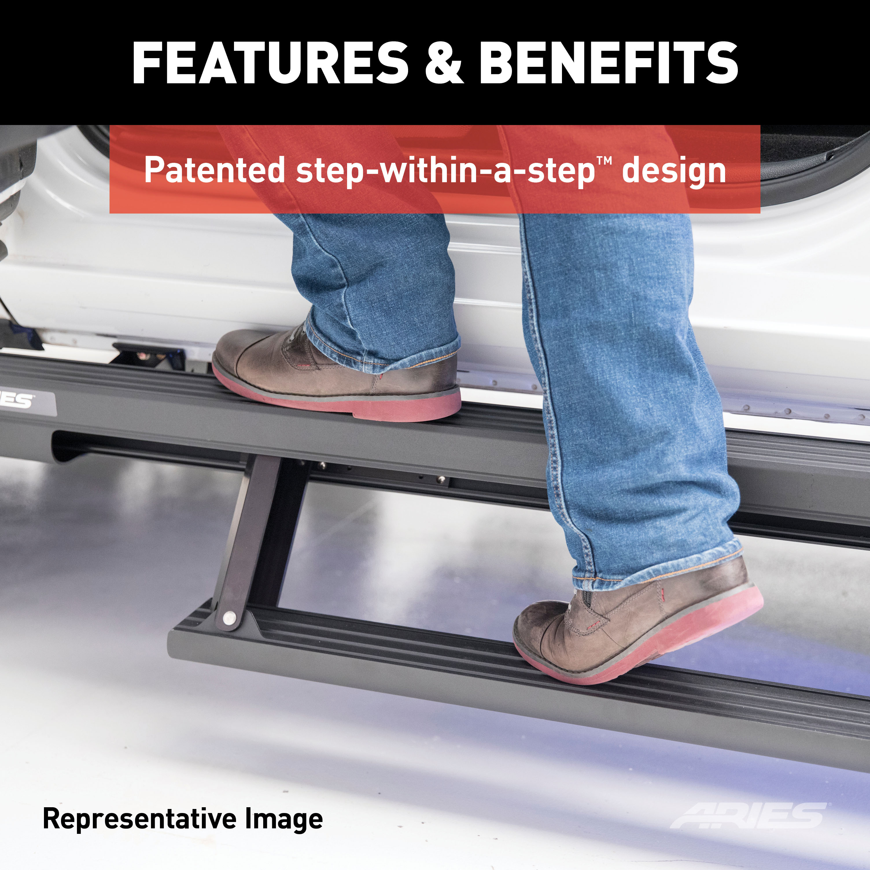
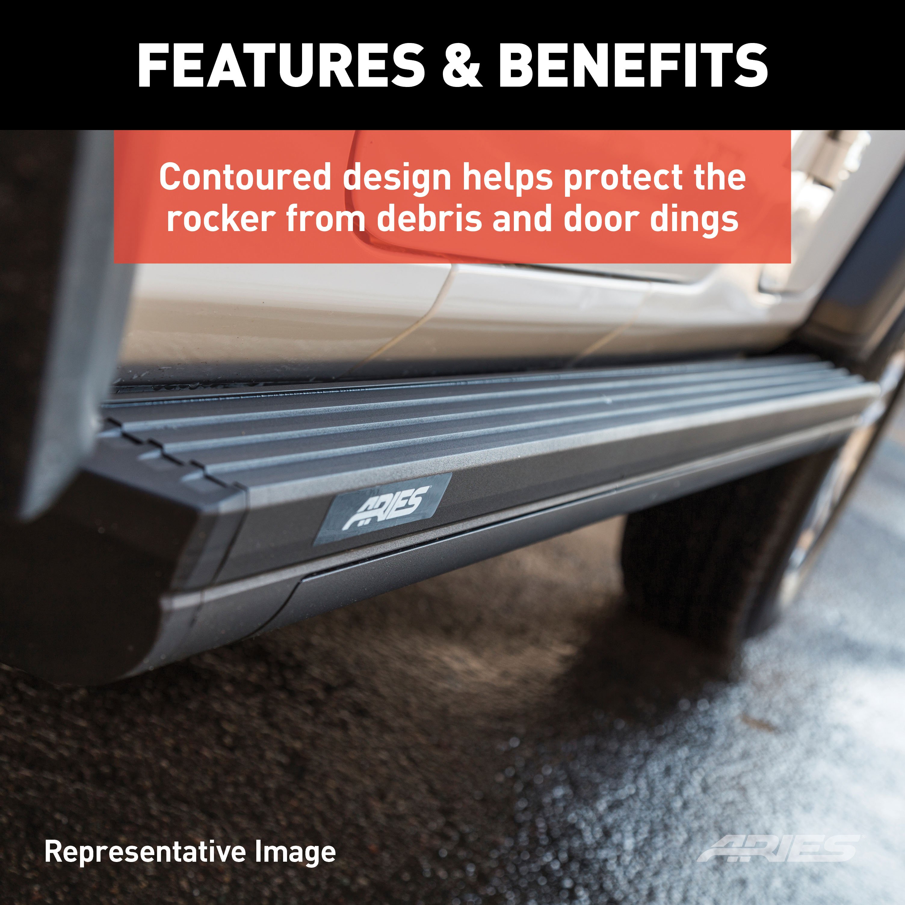
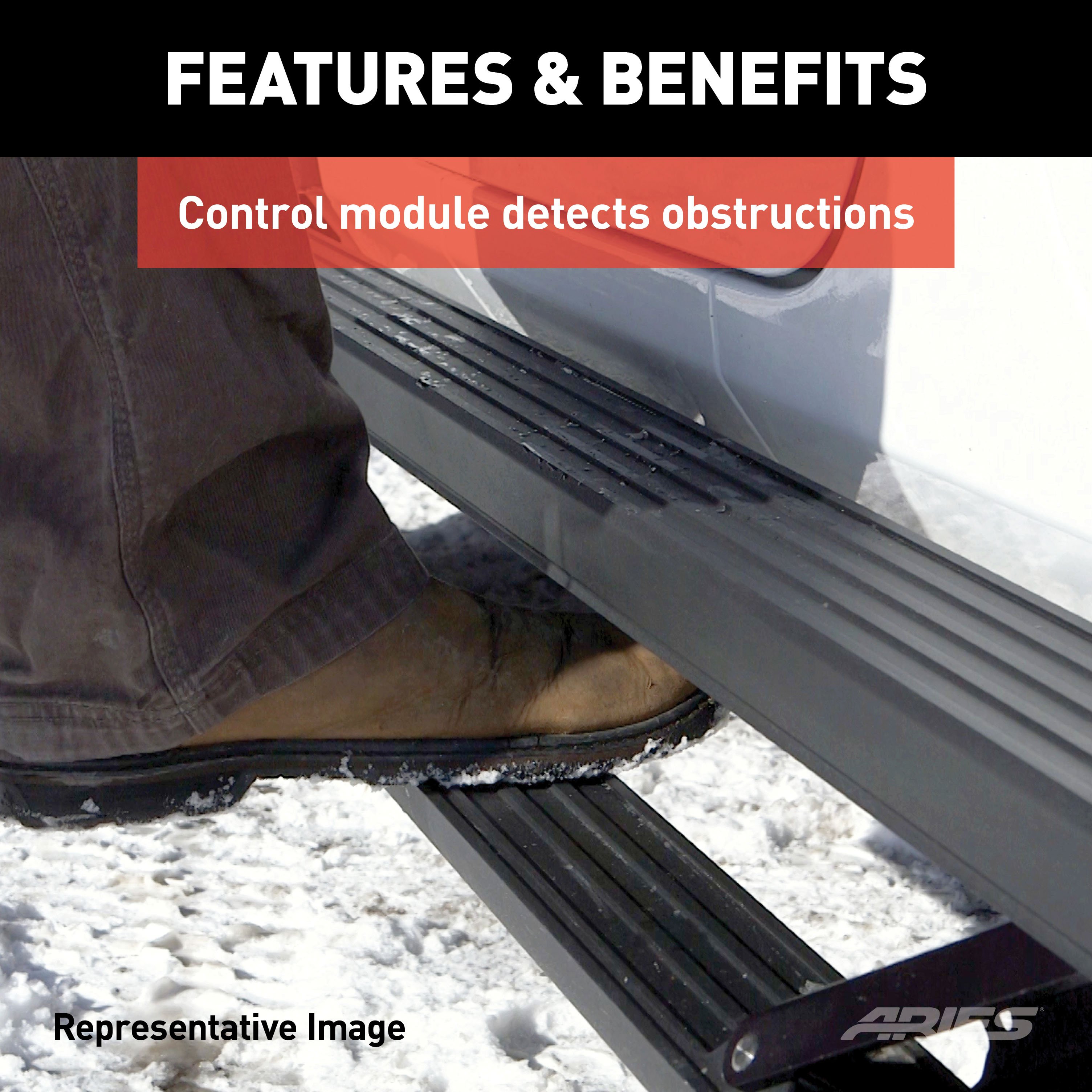
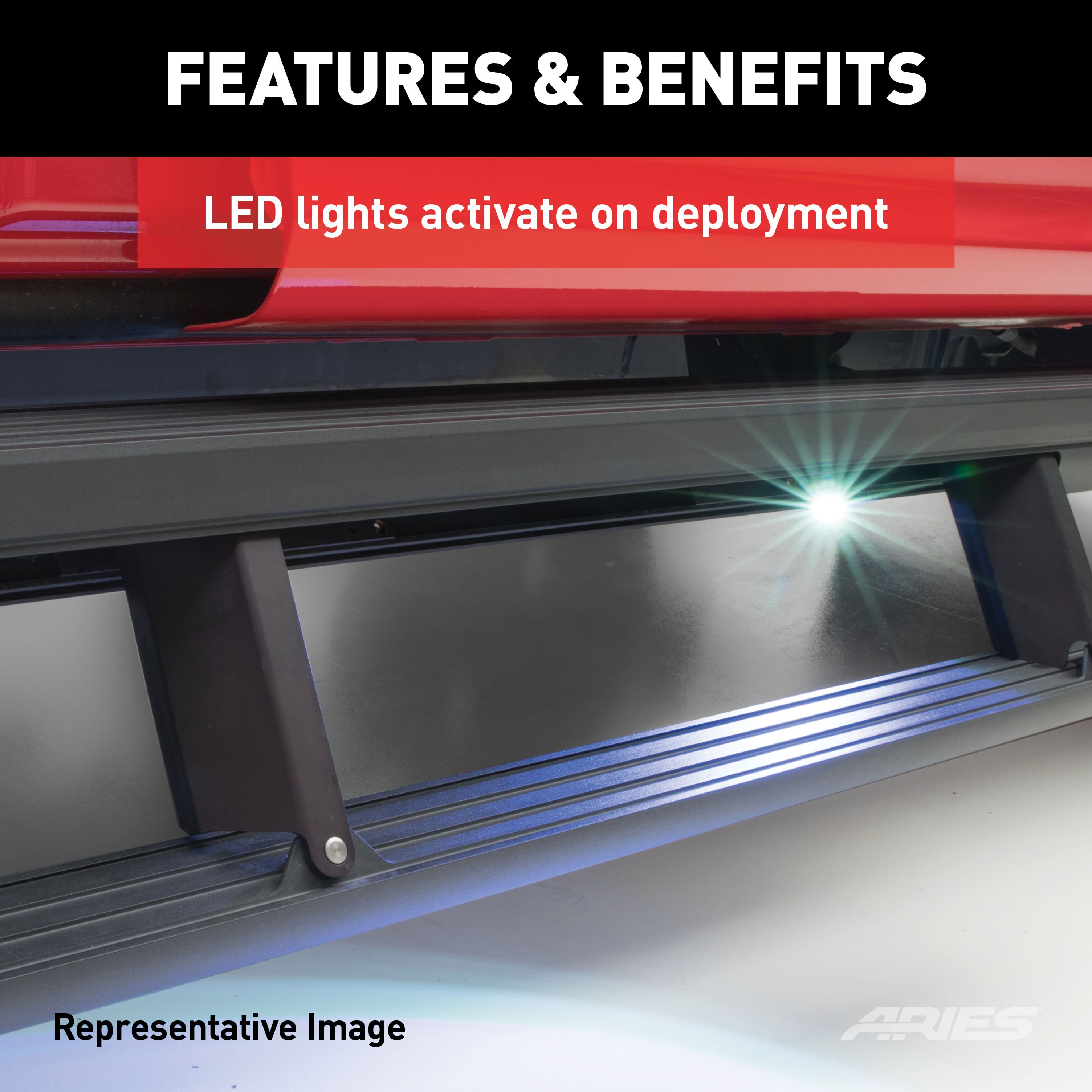
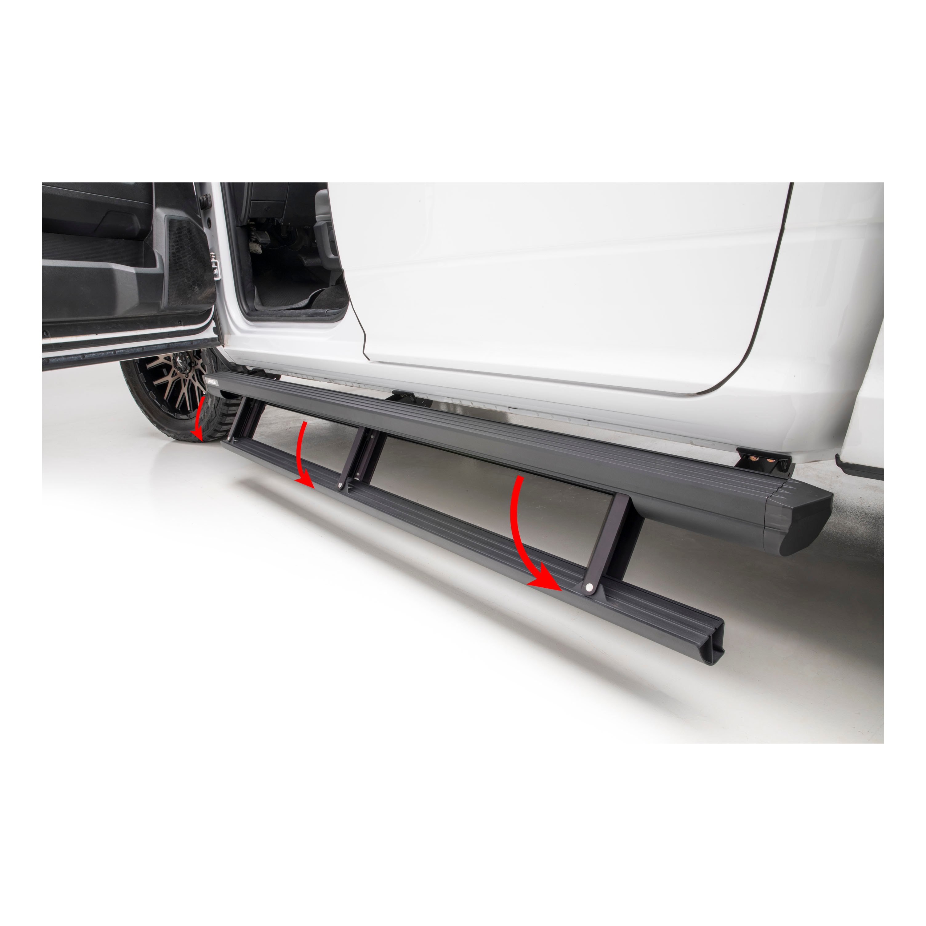
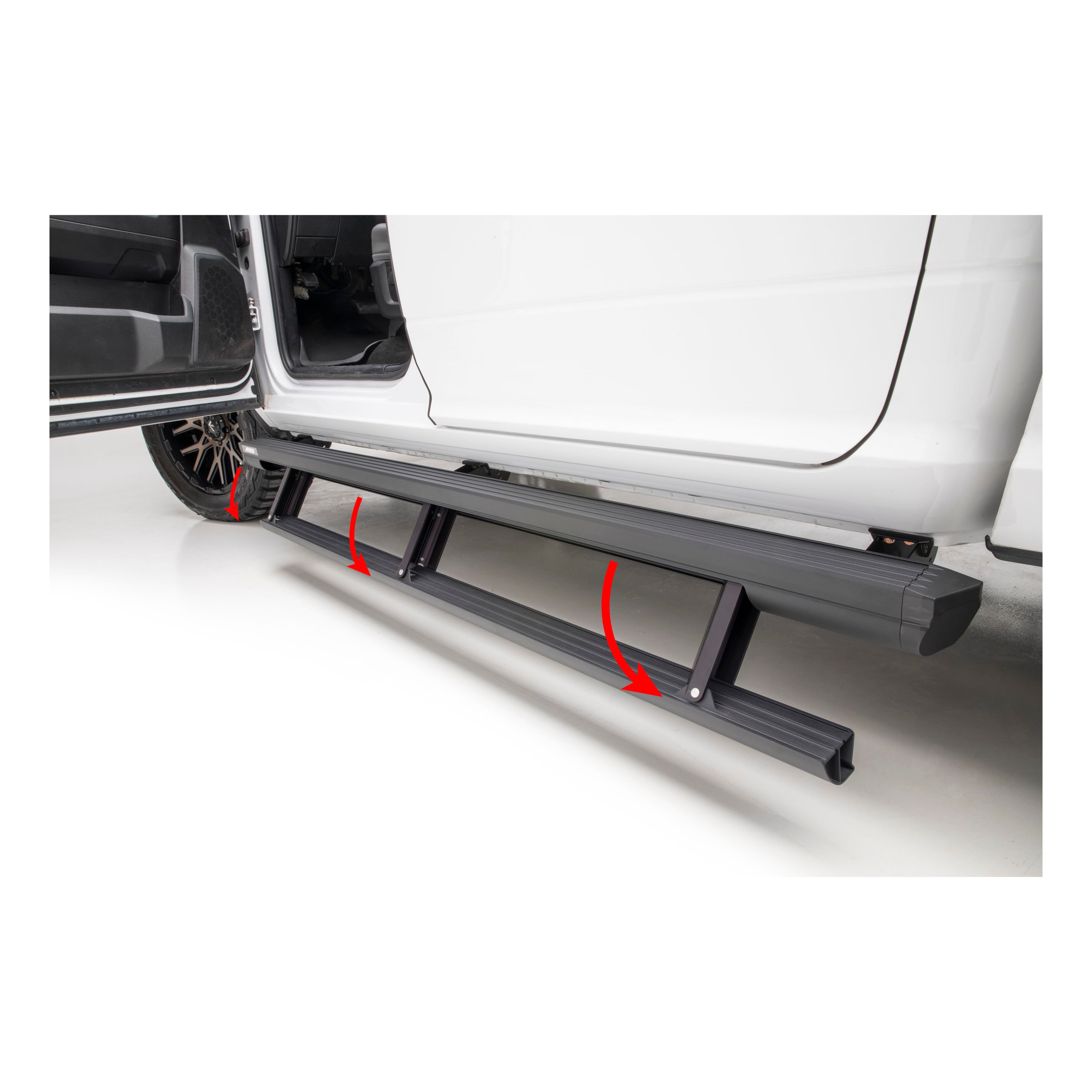
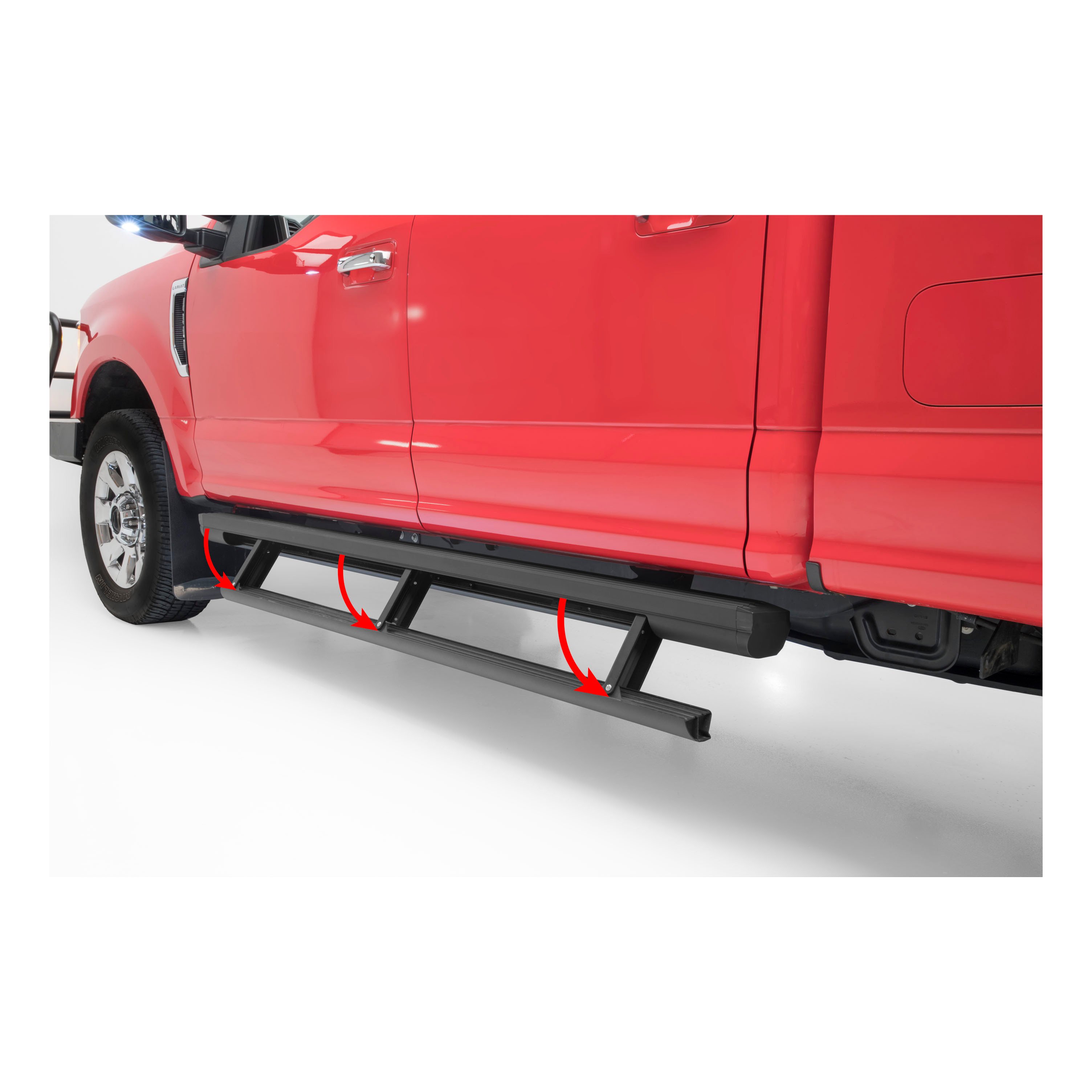
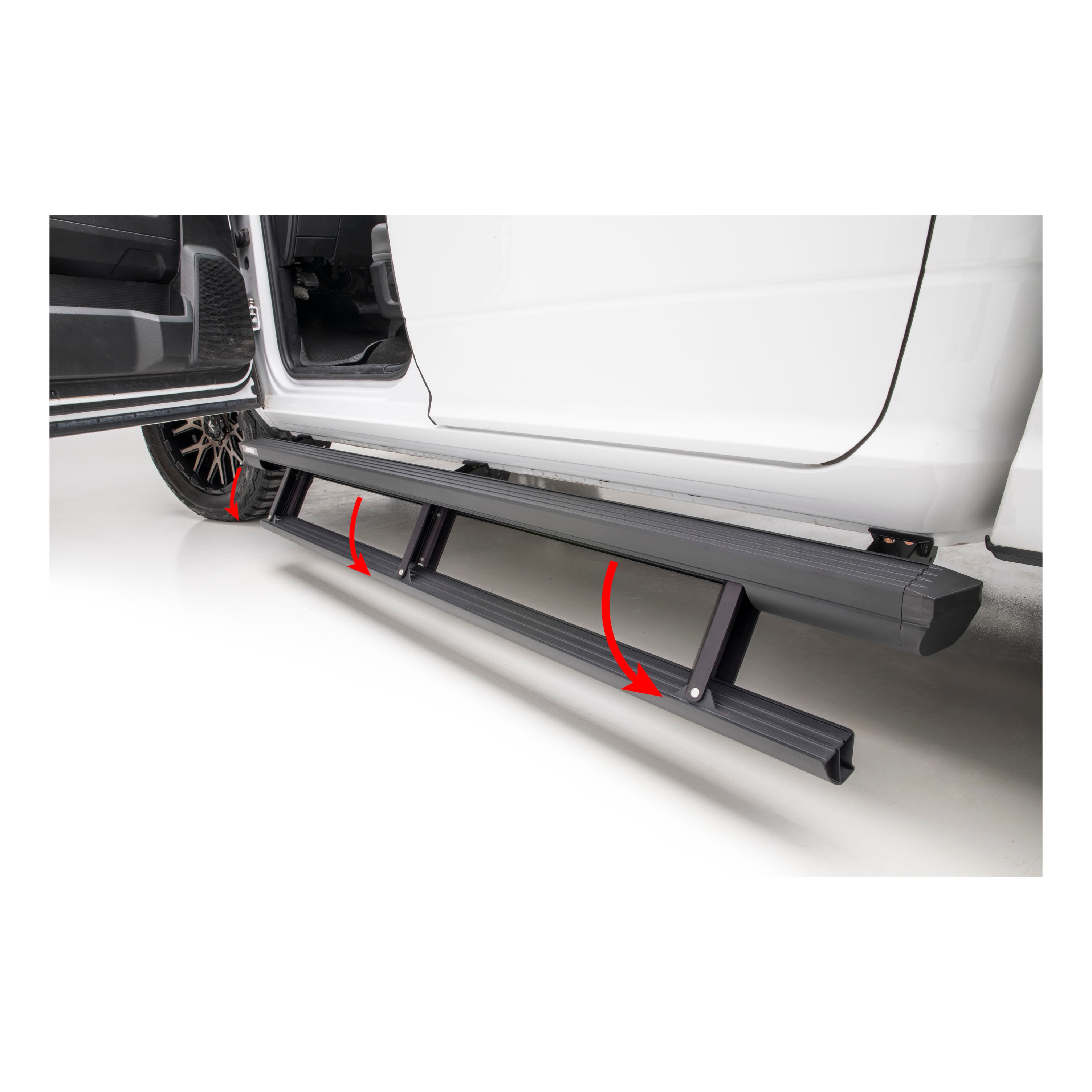
ARIES ActionTrac powered running boards are unique from other power side steps because they are actually two steps in one. This patented step-within-a-step technology -- combined with a no-drill bracket installation, control module operation and powder-coated aluminum construction -- truly makes these retractable running boards an asset for the offroad truck or Jeep, particularly as lifted truck steps. ActionTrac motorized running boards have one 4" wide step on top of the main housing and one 3" wide that automatically deploys as needed. When the door opens, the control module deploys the power step 8" below the main step, 15" below the doorsill, depending on the model. This two-step design offers enhanced safety and easier vehicle entry and exit, especially on large, lifted vehicles. It's also very helpful for families with young children and for elderly passengers. The boards contour to the vehicle and offer extra protection for the rocker panels from small road debris. For additional safety, the module is able to detect any obstructions during operation to avoid pinch hazards. LED lights are also built into the housing to illuminate the steps when deployed. ARIES ActionTrac automatic running boards are made for vehicle-specific installation for a custom fit. They use pre-existing factory holes for the brackets to eliminate drilling. They also do not require any splicing into original factory wiring. These particular automotive running boards fit specific years of the Chevrolet Silverado and GMC Sierra 1500, 2500 HD or 3500 HD crew cab (see application info to verify fitment). Each set is constructed from powder-coated aluminum to be strong, lightweight and non-corrosive. The quiet, maintenance-free rotary motor is shielded within the main housing, along with the powerboard pivot points and all electrical components, protecting them from the harsh elements. NOTE: Boards, brackets and wiring are included.

Explore ARIES products at TowUniverse for top-tier grille guards, side bars, nerf bars, headache racks, and more. Upgrade your vehicle with ARIES today!
ARIES is a fast-paced marketer and innovator of truck, Jeep, SUV and CUV accessories. From automotive enthusiasts to professional builders, our products are built for the champions of individualism, innovation and attitude.
We offer the perfect combination of unique style and durable construction, specializing in custom-fit grille guards, bull bars, side bars and running boards, as well as Jeep Wrangler and Jeep Gladiator accessories.
ARIES products are made vehicle-specific for a custom fit, and they are available for a wide variety of makes and models sold in North America.
Experts available to answer your questions
Call 888-634-9494Limited Lifetime Warranty (Five-Year Finish, Three-Year Parts)
8 compatible vehicles
| Year | Make & Model | Style | Notes |
|---|---|---|---|
| 2019 - 2026 | Chevrolet Silverado 1500 | Crew Cab Pickup · 4-Door | — |
| 2022 | Chevrolet Silverado 1500 LTD | Crew Cab Pickup · 4-Door | — |
| 2020 - 2026 | Chevrolet Silverado 2500 HD | Crew Cab Pickup · 4-Door | — |
| 2020 - 2026 | Chevrolet Silverado 3500 HD | Crew Cab Pickup · 4-Door | — |
| 2019 - 2026 | GMC Sierra 1500 | Crew Cab Pickup · 4-Door | — |
| 2022 | GMC Sierra 1500 Limited | Crew Cab Pickup · 4-Door | — |
| 2020 - 2026 | GMC Sierra 2500 HD | Crew Cab Pickup · 4-Door | — |
| 2020 - 2026 | GMC Sierra 3500 HD | Crew Cab Pickup · 4-Door | — |
Yes, the ARIES ActionTrac 87.6" Powered Running Boards, Select Silverado, Sierra Crew Cab Step Nerf Bar Kit (Part #BBDR3048315) is designed to fit the 2019-2026 Chevrolet Silverado 1500.
The ARIES ActionTrac 87.6" Powered Running Boards, Select Silverado, Sierra Crew Cab Step Nerf Bar Kit (Part #BBDR3048315) fits the following vehicles: 2019-2026 Chevrolet Silverado 1500; 2022 Chevrolet Silverado 1500 LTD; 2020-2026 Chevrolet Silverado 2500 HD; 2020-2026 Chevrolet Silverado 3500 HD; 2019-2026 GMC Sierra 1500; 2022 GMC Sierra 1500 Limited; 2020-2026 GMC Sierra 2500 HD; 2020-2026 GMC Sierra 3500 HD. Always verify your specific year, make, and model before ordering.
The ARIES ActionTrac 87.6" Powered Running Boards, Select Silverado, Sierra Crew Cab Step Nerf Bar Kit (Part #BBDR3048315) fits 2019-2026 Chevrolet Silverado 1500 models. The 2026 model year is the last year covered by this part number. For newer models, check for an updated version.
The ARIES ActionTrac 87.6" Powered Running Boards, Select Silverado, Sierra Crew Cab Step Nerf Bar Kit (Part #BBDR3048315) Refer to the included instructions for installation details. Basic hand tools are typically all you need.
The kit includes 6 mounting brackets, 6 T-rails, 12 Nylock nuts (5/16"), 12 hex bolts (M8 x 30mm), 24 flat washers (M8), 12 lock washers (M8), 4 door sensors, 2 door sensor extensions, 4 magnets, 2 alcohol wipes, 1 power switch, 1 circuit board, 1 anti-seize, 1 wire loom, 1 wiring harness (two-piece), 2 LED lights, 2 LED light brackets, 4 double-sided foam tape squares (3/4" x 3/4"), 4 double-sided tape strips (3/4" x 1"), 4 round double-sided tape pieces, 8 cable ties (8"), 4 adhesive cable tie bases, and 1 mounting bracket for rocker switch. Running boards are sold separately.
Yes. The manual states: 'This is the first of two manuals required to complete this installation. The second manual is included with your side bars / running boards.' You must refer to the second manual to complete the full installation.
No maintenance is required on the waterproof harness or water-resistant motors. If mud or dirt builds up on the steps, spray them off and let them air dry. Mild automotive detergent may be used to clean the product. Do not use dish detergent, abrasive cleaners, abrasive pads, wire brushes or similar products that may damage the finish.
Switch the transportation mode cutoff switch to the off position if your vehicle is sitting idle for longer than one week. This prevents battery drain.
Required tools are: ratchet, drill, torque wrench, hole saw (1"), socket set, heat gun, utility knife, and level.
M8 bolts must be torqued to 7 ft-lbs. This applies to the hex bolts (M8 x 30mm) used to secure the mounting brackets to the body panel.
5/16" bolts must be torqued to 7 ft-lbs.
The installation difficulty level is Moderate. This is based on time and effort involved and may vary depending on the installer's level of expertise, condition of the vehicle, and availability of proper tools and equipment.
There are three mounting locations underneath the vehicle on each side (driver and passenger), for a total of six mounting locations. Brackets are installed at the front, middle, and rear positions on both sides.
Each bracket is secured using one M8 hex bolt (30mm), one lock washer (M8), one flat washer (M8), and anti-seize. The hardware should be snugged but not fully tightened during initial installation.
No. During initial installation, snug the hardware but do not fully tighten. The brackets are tightened to final torque specification (7 ft-lbs for M8 bolts) after all other installation steps are complete.
Yes. Remove the fuse from the wiring harness before installing. Once the fuse is removed, attach that section of the wiring harness to the battery.
If the battery is on the passenger side, attach the provided wiring extension harness to the main wiring harness. Use the provided heat shrink on each connection to prevent corrosion.
Route the wiring harness through the firewall into the cab of the vehicle. Once inside, route the second section of the harness under the carpet from the passenger-side rear to the desired location. Use cable ties to secure the wiring harness in place once it is in the desired location.
Remove the front and rear door trim panels on both sides of the vehicle. Also remove any other vehicle components that could interfere with the wiring harness. Additionally, fold the rear seats up and remove the spare tire tools, jack, mounting bracket, and under-seat storage compartment.
Yes. You must drill a 1" hole through the floor of the vehicle near the rear seat bracket on both the driver and passenger sides. Ensure there are no obstructions in the drilling location before proceeding.
A 1" hole saw is required. This is listed in the Tools Required section and specified in Step 9 for drilling the floor holes.
If there is a plastic body plug near the drilling location, remove the plug, insert the wires through the hole, cut a slot in the plug, and reinstall it.
Driver side: front door sensor (Yellow/Orange), rear door sensor (Purple/Orange), LED light (Brown/Dark brown), actuator (Black/Red). Passenger side: front door sensor (Grey/Green), rear door sensor (White/Blue), LED light (Pink/Brown), actuator (Black/Red).
Wipe the sensor and door with the provided alcohol wipe. Place the double-sided tape on the sensor and attach the sensor to the vehicle. Route the sensor up the door frame and under the carpet to the wiring harness. Repeat this process for all four doors.
Position magnets 3/4" over from the center of the screw on both the front and rear doors. Temporarily position the magnets using the recommended positions shown in the manual. Once all magnet locations are confirmed and the system is operating correctly, mark the positions and permanently install using the round double-sided adhesive.
Yes. On vehicles with aluminum body panels, non-marking tape may be used to temporarily secure the magnets while testing the system before permanent installation with double-sided adhesive.
Locate a suitable spot to mount the power switch bracket. The bracket can be attached using either the 3/4" double-sided tape squares, screws (not provided), or by using a factory screw if one exists in a suitable location. If using screws, confirm there are no wires behind the panel.
Connect the two red wires to the silver terminals and the black wire to the bronze terminal.
Place the circuit board underneath the carpet in a suitable location. Ensure the control module will not interfere with seat movement after installation.
Do not attempt to force the step open or close. Applying force in this condition will damage the product and void your warranty. Refer to the troubleshooting guide on the last page of the instruction manual to resolve potential issues.
Unless you are familiar with the installation and handling of electrical systems, have the electrical installation performed by someone who has that familiarity. Improper electrical installation may result in personal injury.
With the magnets in position, complete the installation of the ActionTrac™ running boards, power the system on, and test the boards by opening each door independently to ensure proper step function.
The fuse rating is 20A, as shown in the wiring diagram.
Yes. This is the first of two required manuals. The second manual is included with your side bars/running boards.
You need a ratchet, drill, torque wrench, 1" hole saw, socket set, heat gun, utility knife, and level.
Yes. You must drill a 1" hole through the vehicle floor near the rear seat bracket on both driver and passenger sides.
Torque M8 bolts to 7 ft-lbs.
Yes. Remove the fuse from the wiring harness before attaching it to the battery.
Switch the transportation mode cutoff switch to the off position to prevent battery drain.
Check the following in order: (1) Confirm the main power switch is in the on position and has power. (2) Confirm the positive and negative connections on the battery are secure. (3) Confirm the fuse is plugged in and not blown. (4) Confirm the control module is plugged in. (5) Confirm the board connections are plugged in and secure. (6) Confirm the door sensors are plugged in. If all connections are secure and power is confirmed, the motor may be bad and the board may need replacement. To test motor function, apply 12 volts directly to the motor leads. If the board does not open, swap the leads and try again. If the board opens, the motor is good.
The door sensor for the non-functioning door is either disconnected or faulty. First, confirm that the door sensor is plugged in. If it is plugged in, the sensor may be bad. To check for a bad sensor, disconnect the sensor and check for continuity with a multi-meter. The sensor is normally a closed switch and should have continuity without the magnet present and should not have continuity when the magnet is placed near the sensor. If continuity is incorrect, replace the sensor.
The magnet may be misaligned or a door sensor may be faulty. First, try adjusting the magnet position. If that does not work, disconnect both sensors and the board should close. Connect only one door sensor and test. If the board closes, the alignment for that door is good. Connect the second sensor and repeat. If a sensor is causing the board to stay open, test it with a multi-meter for continuity. The sensor is normally a closed switch and should have continuity without the magnet present and should not have continuity when the magnet is placed near the sensor. If continuity is incorrect, replace the sensor.
Apply graphite lubricant to all pivot points. If excessive squeaking still occurs, check for worn out bushings or obvious areas of metal on metal contact.
The LED is either not connected or is faulty. First, confirm that the LED connection is plugged in and secure. If it is connected, inspect the LED and wiring harness for damage. To test LED functionality, apply 12 volts directly to the LED. If the LED will not turn on when directly connected, it will need to be replaced.
The door sensors may be incorrect or the motor harness polarity may be reversed. First, check the sensors by disconnecting them and testing for continuity with a multi-meter. The sensor is normally a closed switch and should have continuity without the magnet present and should not have continuity when the magnet is placed near the sensor. If sensors are confirmed to be correct (normally closed) and the board still operates in reverse, the motor electrical harness may be reversed. Replace the board.
A programmed safety limit has been reached. Using the main switch, power off the boards for 5–10 seconds and turn them back on. The boards should cycle when turned back on. The LED will flash 8 times when this issue occurs.
This is a software limitation. Close the doors and open them individually. A software limitation will prevent the boards from opening if both the front and rear doors are opened simultaneously. Closing the doors and opening them one at a time will reset the board.
On Sale Today
Original price was $2,634.95. Current price is $1,998.95.You save $636.00 (24%)
Free Shipping
Ships free on all orders
 Authorized Dealer
Quick Ship
In stock and ready to ship — order now!
FREE ShippingFREE SHIPPING
Estimated delivery Wed, Sep 16 - Sat, Sep 19
Order before 2 PM EST Monday–Friday for same-day processing
Guaranteed safe & secure checkout
No reviews have been added for this product.