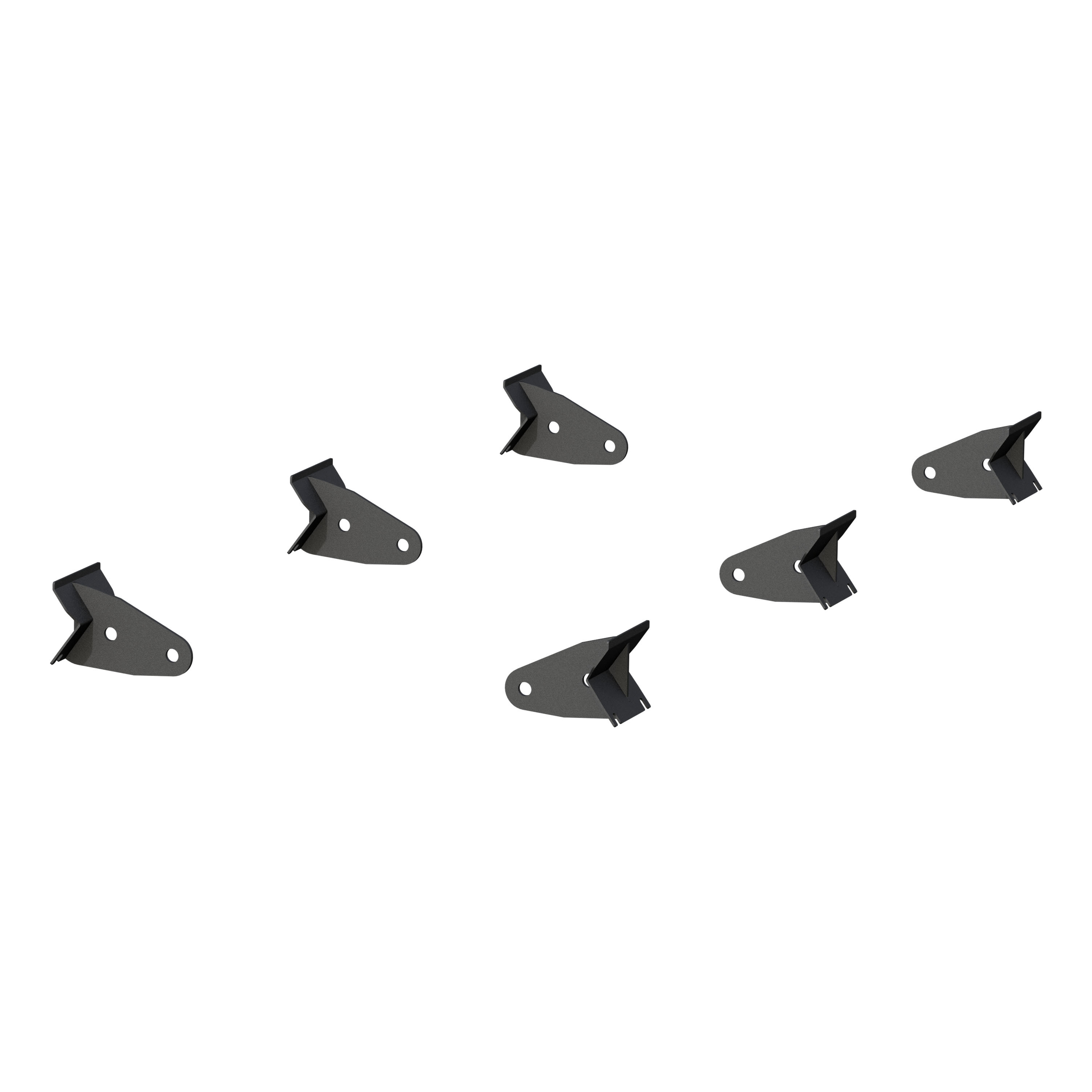
Universal ActionTrac Mounting Brackets (6-Pack, Fabricated Brackets Required)ARIESOriginal price was $695.95. Current price is $527.95.In Stock
View productOur in-house experts typically reply within one business day.

ARIES




Always the correct part
We know our products
Quality Products
Free Shipping!
Always the correct part
We know our products
Quality Products
Free Shipping!
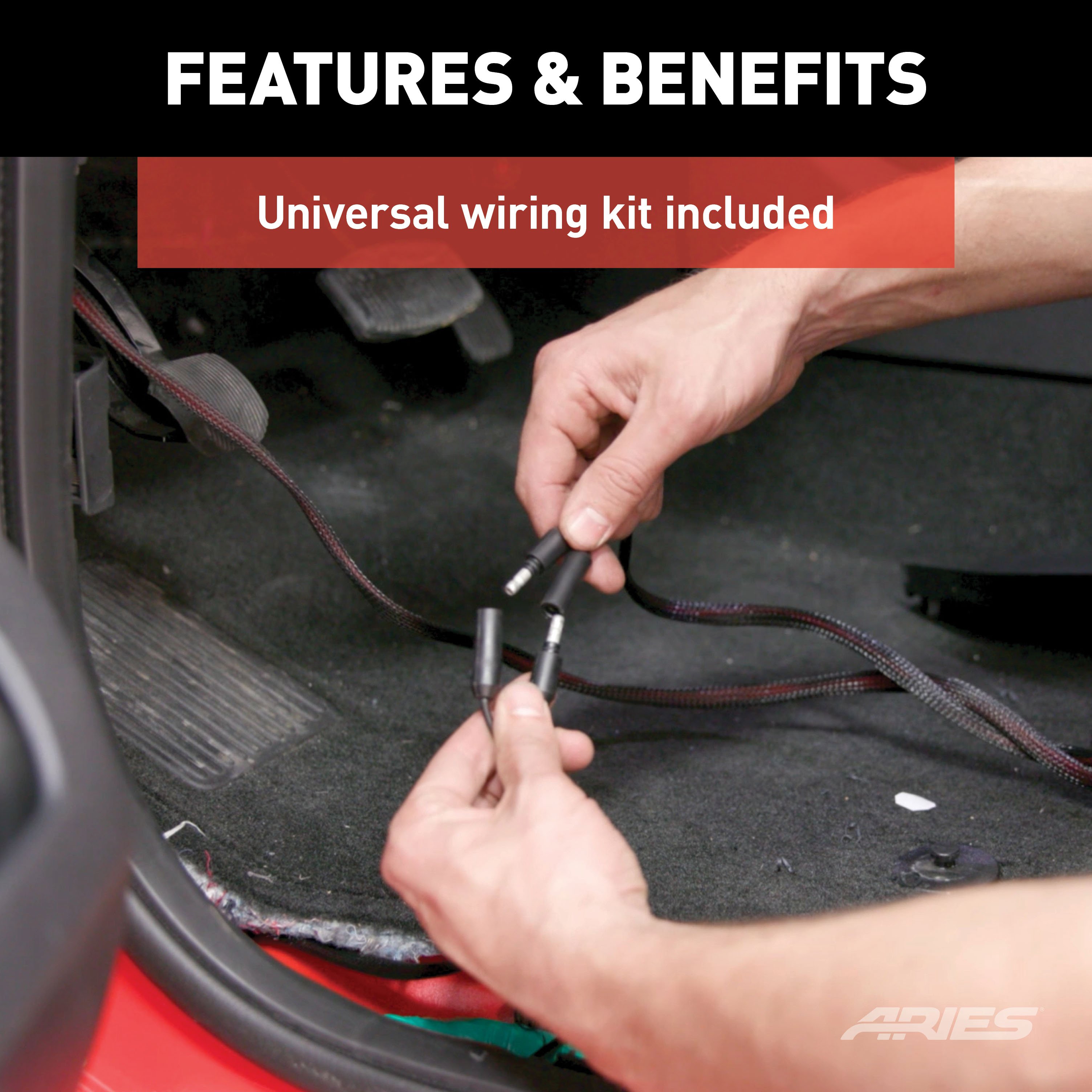
Includes wiring and two sets of 3 brackets for board attachment only



Warranty: Limited Lifetime Warranty (Five-Year Finish, Three-Year Parts)
Finish: TEXTURED BLACK POWDER COAT
Material: Carbon Steel
Side Component Type: Bracket
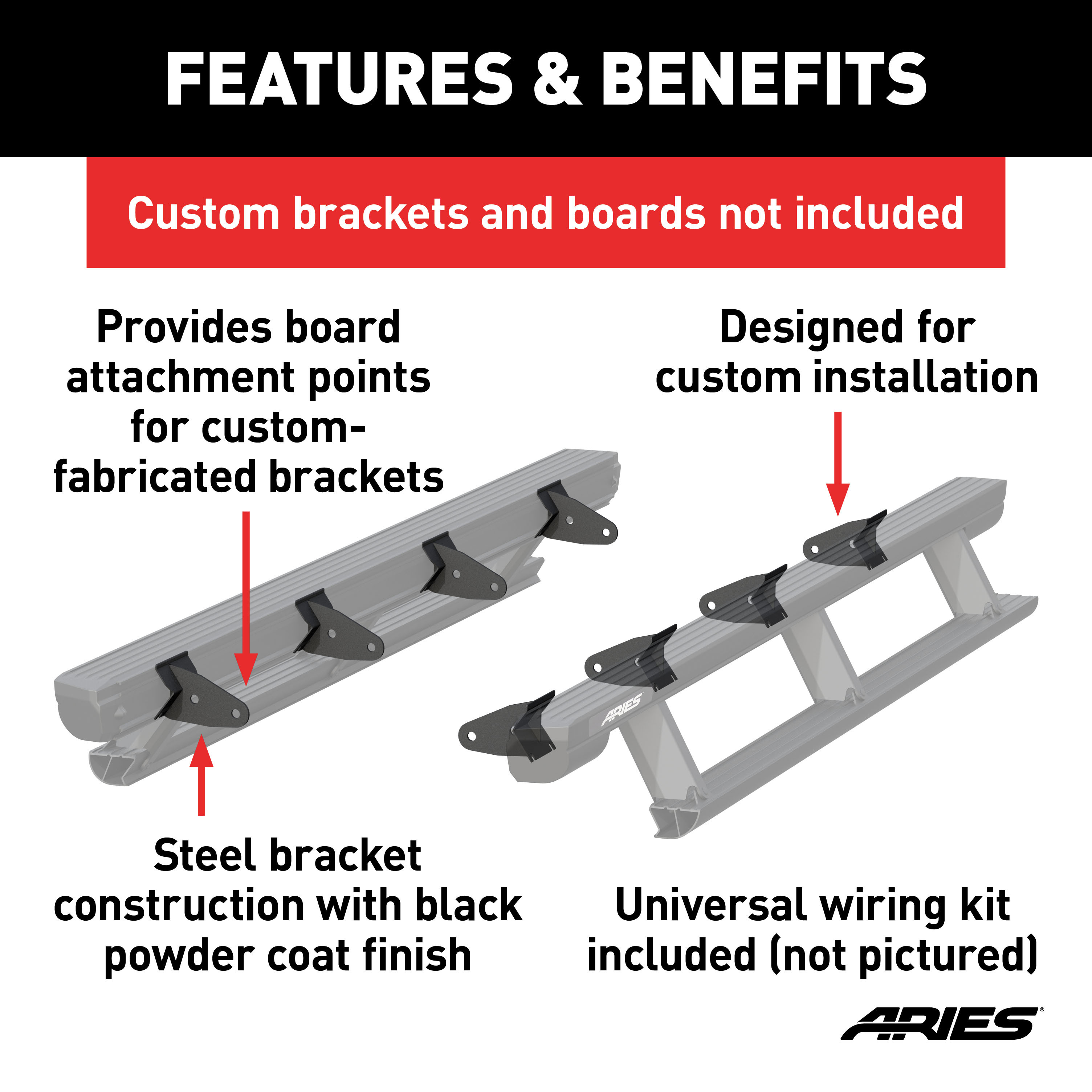
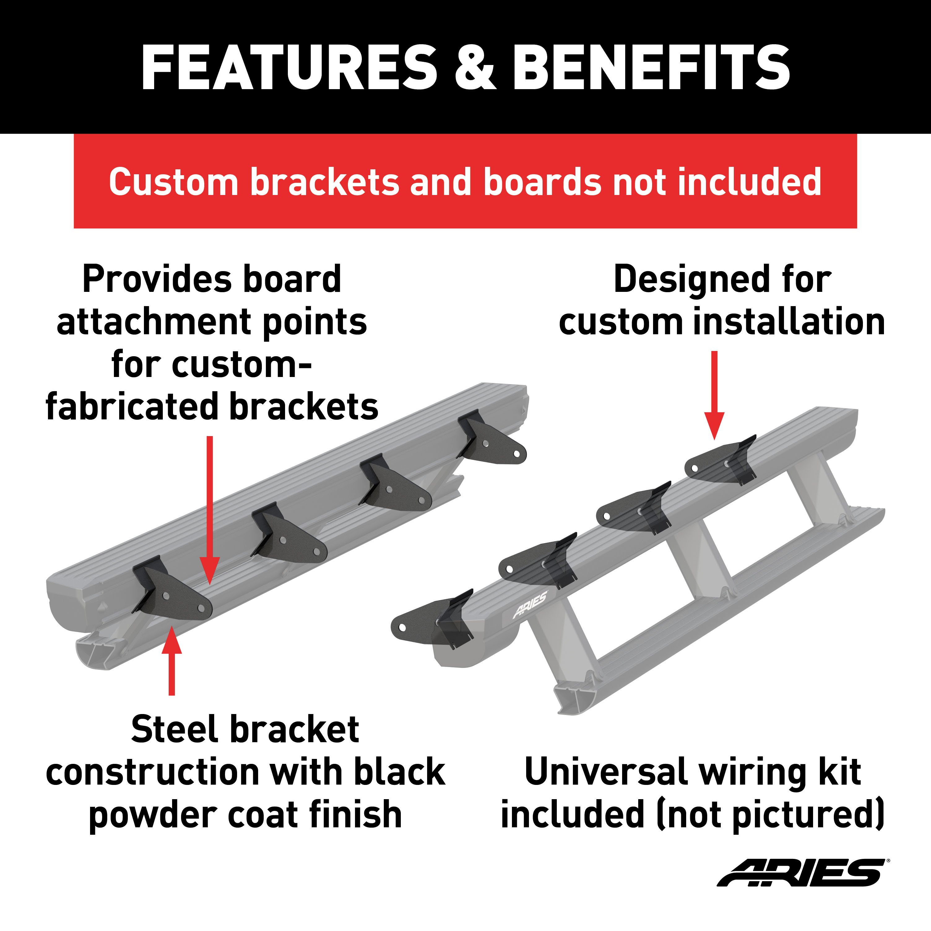
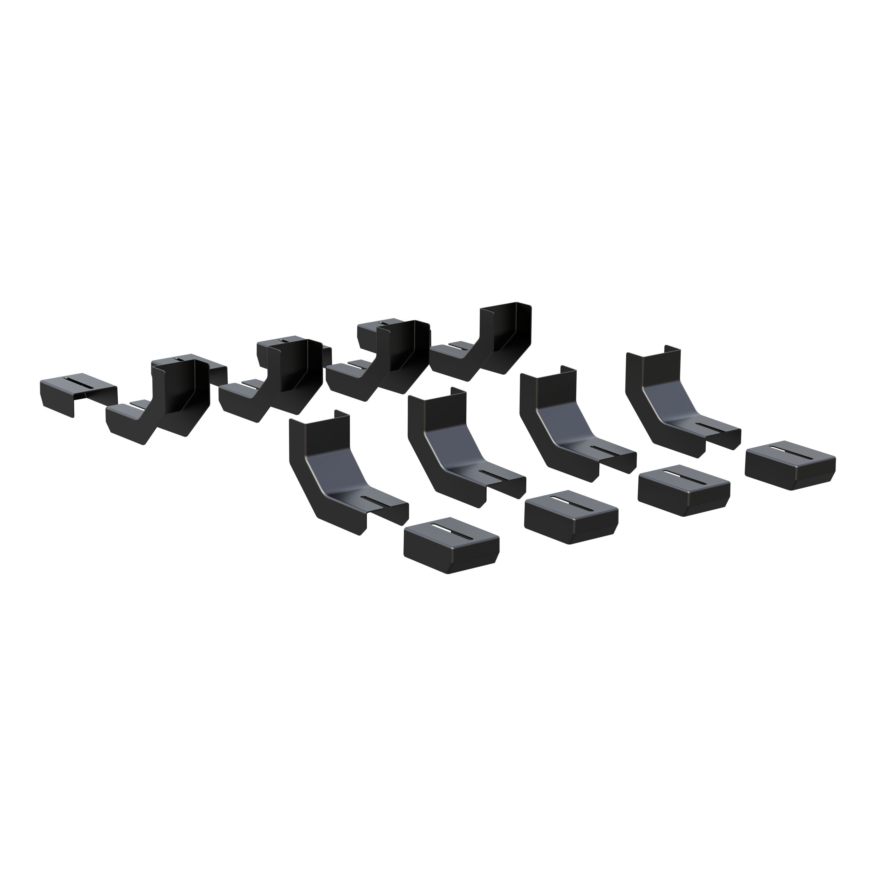
ARIES universal ActionTrac brackets are a custom builder / custom fabrication solution for installing ARIES ActionTrac powered running boards. Normally, ActionTrac boards are engineered to install with vehicle-specific brackets. However, if vehicle-specific brackets are not available, these universal brackets offer a custom-fab alternative. The brackets in this set attach to the ActionTrac boards, equipping them with attachment points. Custom-fabricated brackets must then be made to attach these brackets to the vehicle (not included). This kit comes with brackets for the running boards only. Brackets for attaching the boards to the vehicle are not included. Running boards must also be purchased separately.

Explore ARIES products at TowUniverse for top-tier grille guards, side bars, nerf bars, headache racks, and more. Upgrade your vehicle with ARIES today!
ARIES is a fast-paced marketer and innovator of truck, Jeep, SUV and CUV accessories. From automotive enthusiasts to professional builders, our products are built for the champions of individualism, innovation and attitude.
We offer the perfect combination of unique style and durable construction, specializing in custom-fit grille guards, bull bars, side bars and running boards, as well as Jeep Wrangler and Jeep Gladiator accessories.
ARIES products are made vehicle-specific for a custom fit, and they are available for a wide variety of makes and models sold in North America.
Experts available to answer your questions
Call 888-634-9494Limited Lifetime Warranty (Five-Year Finish, Three-Year Parts)
The kit includes: 8 board mounting brackets (universal), 8 T-rails, 16 flat washers (5/16"), 16 Nylock nuts (5/16"), 2 rubber grommets, 4 door sensors, 4 magnets, 2 alcohol wipes, 1 power switch, 1 circuit board, 1 anti-seize compound, 1 wire loom, 1 two-piece wiring harness, 2 LED lights, 2 LED light brackets, 4 pieces of 3/4" x 1" double-sided tape, 4 round double-sided tape pieces, 8 cable ties (8"), 4 adhesive cable tie bases, and 1 mounting bracket for rocker switch. Running boards are sold separately.
Required tools are: ratchet, drill, socket set, drill bit set, and level.
The installation difficulty is rated as Moderate. This rating is based on time and effort involved and may vary depending on installer expertise, vehicle condition, and availability of proper tools and equipment.
Yes, the board mounting brackets are universal. However, the manual notes that fabrication of vehicle attachment brackets is the builder's responsibility, and mounting brackets must be of sufficient strength for the load rating of the ActionTrac™ running boards. The wiring harness routing may vary depending on vehicle configuration, particularly regarding floor plugs behind driver and passenger seats.
Yes, the system can be installed on two-door vehicles. However, the rear door sensor connectors must not be plugged in. Instead, route and hide the rear sensor connectors underneath the carpet with the rest of the wiring harness.
A 20A fuse is required. The fuse must be removed before installation and attached to the battery section of the wiring harness.
Remove the front and rear door trim panels on both sides of the vehicle. Also remove any other vehicle components that could interfere with the wiring harness routing.
The manual does not explicitly state whether the battery must be disconnected. However, it does warn that improper electrical installation may result in personal injury and recommends having someone familiar with electrical systems perform this step if you are not.
After removing the fuse, attach one section of the wiring harness to the battery and route the opposite end through the firewall into the cab. Zip-tie it in place. The second section of the wiring harness should be routed under the carpet from the passenger-side rear to the desired location. Power and sensor wires should be routed to the front of the vehicle underneath the carpet. Rear actuator and LED light wires are routed through floor plugs (if available) or through a drilled 1" hole with a rubber grommet.
Connect the two red wires to the silver terminals and the black wire to the bronze terminal on the power switch.
Plug the door sensor into the wiring harness and route it up the door frame under the carpet. Wipe both the sensor and door with the provided alcohol wipe. Apply a 1" x 3/4" piece of double-sided tape to the sensor and attach it to the vehicle. Repeat for all four doors. On two-door vehicles, do not plug rear door sensors into the rear door sensor connectors; instead route and hide them under the carpet.
Temporarily position the magnets on the doors so they align with the sensors. On vehicles with aluminum body panels, non-marking tape may be used to temporarily secure the magnets. Complete the running boards installation, power the system on, and test by opening each door independently to ensure proper step function. Once all magnet locations are confirmed and the system operates correctly, mark the positions and permanently install using the round double-sided adhesive tape.
Locate a spot to mount the power switch bracket on the dash or interior panel. The bracket can be attached using either 3/4" double-sided tape squares, screws (not provided), or by using a factory screw if one exists in a suitable location. If using screws, confirm there are no wires behind the panel.
Plug in the circuit board and place it underneath the carpet in a suitable location. Ensure the control module will not interfere with seat movement after installation.
Drilling is required only if there is no floor plug behind the driver or passenger seat. If no plug exists, locate a position close to the rear bracket and drill a 1" hole through the floor of the vehicle. Before drilling, ensure there are no obstructions in the drilling location. Secure the wires in place with the provided rubber grommet.
A 1" hole must be drilled through the floor of the vehicle if no factory floor plug exists. The hole should be located close to the rear bracket.
Yes. After inserting the rear wires through the floor hole, cut a slot in the floor plug and re-insert it into the hole.
The torque specification for 5/16" bolts is 7 ft-lbs. This is the standard torque setting unless otherwise noted in the installation instructions.
Driver-side: front door sensor (Yellow/Orange), rear door sensor (Purple/Orange). Passenger-side: front door sensor (Grey/Green), rear door sensor (White/Blue). The wiring harness uses an 18-pin connector.
Driver-side LED light: Brown/Dark brown. Passenger-side LED light: Pink/Brown.
Both driver-side and passenger-side actuators use Black/Red wire colors.
Do not attempt to force the step open or close. Applying force in this condition will damage the product and void your warranty. Refer to the troubleshooting guide on the last page of the instruction manual to resolve potential issues.
Switch the power switch to the off position if your vehicle is sitting idle for longer than one week. This prevents battery drain.
No maintenance is required on the waterproof harness or water-resistant motors. If mud or dirt builds up on the steps, simply spray them off and let them air dry.
Mild automotive detergent may be used to clean the product. Do not use dish detergent, abrasive cleaners, abrasive pads, wire brushes or other similar products that may damage the finish.
Periodic inspection of your product should be performed to ensure all wiring connections, hardware and/or components remain secure.
The board mounting brackets are universal, but vehicle attachment brackets must be fabricated by the builder and be of sufficient strength for the load rating. Wiring routing varies by vehicle configuration (floor plugs may or may not be present).
You need a ratchet, drill, socket set, drill bit set, and level.
Yes, you must remove the front and rear door trim panels on both sides of the vehicle, plus any other components that could interfere with wiring harness routing.
7 ft-lbs.
Do not force it. Forcing the step will damage the product and void the warranty. Refer to the troubleshooting guide instead.
Use mild automotive detergent only. Do not use dish detergent, abrasive cleaners, abrasive pads, or wire brushes.
Check the following in order: (1) Confirm the main power switch is in the on position and has power. (2) Confirm the positive and negative battery connections are secure. (3) Confirm the 20A fuse is plugged in and not blown. (4) Confirm the control module is plugged in. (5) Confirm the board connections are plugged in and secure. (6) Confirm the door sensors are plugged in. If all connections are secure, the motor may be bad and the board may need replacement.
The door sensor for the non-functioning door is either disconnected or faulty. First, confirm the door sensor is plugged in. If it is plugged in, the sensor may be bad. To test, disconnect the sensor and check for continuity with a multi-meter. The sensor is normally a closed switch and should have continuity without the magnet present and should not have continuity when the magnet is placed near the sensor. If the sensor fails this test, replace it.
The magnet may be misaligned or a door sensor may be faulty. First, adjust the magnet position. If that does not work, disconnect both sensors and the board should close. Connect only one door sensor and test. If the board closes, that door's alignment is good. Connect the second sensor and repeat. If a sensor is faulty, test it with a multi-meter for continuity (normally closed switch: continuity without magnet, no continuity with magnet present). Replace any faulty sensor.
Apply graphite lubricant to all pivot points. If excessive squeaking still occurs, check for worn out bushings or obvious areas of metal-on-metal contact.
The LED is either not connected or faulty. First, confirm the LED connection is plugged in and secure. If it is connected, inspect the LED and wiring harness for damage. To test LED functionality, apply 12 volts directly to the LED. If the LED will not turn on when directly connected, it needs to be replaced.
The door sensors may be incorrect or the motor harness polarity may be reversed. First, test the sensors with a multi-meter for continuity. The sensors should be normally closed switches: continuity without the magnet present and no continuity when the magnet is placed near the sensor. If sensors are confirmed correct and the board still operates in reverse, the motor electrical harness may be reversed. Replace the board.
A programmed safety limit has been reached. Using the main switch, power off the boards for 5–10 seconds and turn them back on. The boards should cycle when turned back on. The LED will flash 8 times when this issue occurs.
Yes, this is a software limitation. The boards will not open if both the front and rear doors are opened simultaneously. Close the doors and open them individually. Opening them one at a time will reset the board and allow normal operation.
On Sale Today
Original price was $762.95. Current price is $578.95.You save $184.00 (24%)
Free Shipping
Ships free on all orders
 Authorized Dealer


Quick Ship
In stock and ready to ship — order now!
Shipping from Fife, WAFREE SHIPPING
Estimated delivery Tue, Sep 29 - Thu, Oct 1
Order before 2 PM EST Monday–Friday for same-day processing
Guaranteed safe & secure checkout
No reviews have been added for this product.