B&W Trailer Hitches Custom Installation Brackets For Universal Mounting Rails For Some RAM Trucks Fifth Wheel Trailer Hitch Bracket BQVLRVR2600B&W Trailer Hitches$130.00In Stock
View productOur in-house experts typically reply within one business day.

B&W Trailer Hitches
Verify Fitment
Select your vehicle to confirm this part fits.

Always the correct part
We know our products
Quality Products
Free Shipping!
Always the correct part
We know our products
Quality Products
Free Shipping!

| PROP 65 WARNING: | WARNING: This product may expose you to chemicals including Nickel (Metallic), which is known to the state of California to cause cancer. For more information, go to www.P54Warnings.ca.gov. |

B&W Trailer Hitches is an American manufacturer known for durable, innovative towing products, including gooseneck hitches, fifth-wheel hitches, receiver hitches, and ball mounts. Built in Kansas by employee-owners, B&W products are engineered for dependable performance, easy installation, and long-lasting quality.
B&W Trailer Hitches is an American manufacturer known for building innovative, dependable towing products designed to make hitching easier and towing more comfortable. The company began in 1987 in Humboldt, Kansas, when founders Roger Baker and Joe Works combined their fabrication experience to build custom truck beds and solve common problems faced by truck owners.
B&W changed the gooseneck hitch industry with the introduction of the Turnoverball Gooseneck Hitch. Its under-bed mounting system and reversible hitch ball allowed truck owners to quickly store the ball beneath the bed, leaving a clean and unobstructed surface when the hitch was not in use. B&W later applied the same practical approach to the Companion Fifth Wheel Hitch, creating a removable fifth-wheel hitch engineered for a quiet, smooth, and secure towing experience.
Today, B&W manufactures gooseneck hitches, fifth-wheel hitches, receiver hitches, ball mounts, and towing accessories at its nearly 600,000-square-foot facility. The company is owned by approximately 500 employee-owners who remain committed to American manufacturing, trusted materials, skilled craftsmanship, and long-lasting product quality.
Whether you are towing a work trailer, livestock trailer, camper, or fifth wheel, B&W Trailer Hitches offers thoughtfully engineered towing equipment built to perform mile after mile.
Experts available to answer your questions
Call 888-634-94941 compatible vehicles
| Year | Make & Model | Notes |
|---|---|---|
| 2019 - 2024 | Ram 1500 | Excludes beds with gussets on front end of bed rails |
The B&W Trailer Hitches Custom Installation Brackets For Universal Mounting Rails For Some RAM Trucks Fifth Wheel Trailer Hitch Bracket BQVLRVR2604 (Part #BQVLRVR2604) fits 2019-2024 Ram 1500 models. The 2024 model year is the last year covered by this part number. For newer models, check for an updated version.
The B&W Trailer Hitches Custom Installation Brackets For Universal Mounting Rails For Some RAM Trucks Fifth Wheel Trailer Hitch Bracket BQVLRVR2604 (Part #BQVLRVR2604) fits the following vehicles: 2019-2024 Ram 1500. Always verify your specific year, make, and model before ordering.
Yes, the B&W Trailer Hitches Custom Installation Brackets For Universal Mounting Rails For Some RAM Trucks Fifth Wheel Trailer Hitch Bracket BQVLRVR2604 (Part #BQVLRVR2604) is designed to fit the 2019-2024 Ram 1500.
The B&W Trailer Hitches Custom Installation Brackets For Universal Mounting Rails For Some RAM Trucks Fifth Wheel Trailer Hitch Bracket BQVLRVR2604 (Part #BQVLRVR2604) Refer to the included instructions for installation details. Basic hand tools are typically all you need.
The RVK2604 fits 2019–2025 Ram 1500 trucks, but excludes RAM 1500 Classic and RAM TRX models. It also cannot be installed on beds with gussets on the front end of the bed rails. Verify your truck model and bed configuration before purchasing.
If your truck has a removable bed liner, it must be removed before installation so the mounting rails can connect directly with the bed. Spray-in bed liners are acceptable and do not need to be removed, but you must account for their thickness when measuring and marking hole locations.
Required tools include: impact wrench or ratchet with 3/4" socket, 3/4" box end wrench, drill with 1/8" and 9/16" drill bits, tape measure, torque wrench, center punch tool, hammer, flashlight, eye protection, and ear protection. Verify all parts and hardware are present before starting.
It may be necessary to remove the spare tire and/or heat shield before installation. Check clearance during the drilling phase; if interference occurs, remove these components. Reinstall them after the mounting rail installation is complete.
Some steps of the Patriot rail kit assembly require two people. Specifically, when installing the nut guides and cap screws on trucks with four-corner air suspension or when positioning the forward mounting rail, a second person is needed to hold the nut guide or thread the cap screw while another person guides it from above.
For short beds (less than 8 feet long), position the rear mounting rail 28–7/8" from the rear edge of the bed. Center the rail side-to-side by measuring the distance from each side of the bed to the edge of the rail; both measurements should be equal. Refer to Figure A1 in the manual for the correct positioning.
Yes, drilling is required. You must drill five pilot holes (1/8") in the rear mounting rail location and five in the forward mounting rail location, then enlarge each to 9/16". The hole pattern differs depending on whether your truck has coil spring suspension or four-corner air suspension; refer to Figure A2 to identify the correct holes for your suspension type.
Before drilling, carefully examine the area under the truck where modification will occur. Truck components such as the fuel tank, air tanks, tubing, and wiring may be directly below the bed. Ensure no truck components are damaged during drilling, as damage to the fuel tank or other critical components may result in property damage, serious injury, or death.
The 5/16" thick offset spacers function as space fillers between the mounting rails and the truck bed to account for bed corrugation. Always place a spacer in the gap above the bed at each of the five drilled positions. Failure to use spacers will result in property damage when hardware is tightened.
Insert the coil end of the fish wire into the 1" round hole in the frame and thread it toward the rear of the truck, exiting through the larger hole in the bottom of the frame. Pass the locking strap onto the fish wire and attach the coil end to the carriage bolt. Push the locking strap completely into the frame, then pull the carriage bolt through using the fish wire. Once the threaded portion protrudes, push the circle frame spacer over the bolt into the hole, remove the fish wire, thread the bolt retainer onto the bolt, and tighten until flush with the frame.
The rear side plates install so that the two flanges on the top of the side plate are on either side of the bed cross member directly behind the axle. Pass the flanges over the frame and around the cross member while guiding the rear side plate holes over the carriage bolts. The flanges should be flat against the bottom of the bed.
Yes. On trucks with coil spring suspension, use 1/2" x 2" carriage bolts for all five rear mounting rail positions. On trucks with four-corner air suspension, use 1/2" x 2" cap screws with nut guides for the two outside rearward holes (because air tanks block access underneath), and 1/2" x 2" carriage bolts for the three remaining positions. The center carriage bolt on both suspension types requires a 2" x 1–1/2" x 5/16" spacer instead of a flat washer.
Place the forward mounting rail in the truck bed in front of the rear mounting rail. Position the Patriot base over the rail attachment points and carefully lower it until the pin tabs pass through the attachment points on the rear mounting rail. Attach the forward mounting rail to the forward mounting points on the base. The base should rest flat against the top of the rails. Before drilling, pull the RV base toward the rear of the truck and push the forward rail toward the cab to correctly space the mounting rails.
On the driver side of the frame near the rectangle hole where the carriage bolt is installed, pass the 1/2" U-bolt up between the fuel tank and the frame with the threaded ends toward the rear of the truck. Ensure no brake lines, wiring, or tubing are between the U-bolt and frame. When the leg of the U-bolt passes the top of the frame, rotate the legs toward the outside of the frame. Repeat on the passenger side. The U-bolt passes through holes in the front side plate along with the carriage bolt.
For trucks equipped with a fuel tank skid plate, the skid plate support attached to the frame behind the tank must be loosened to allow the U-bolt to install. Loosen the three bolts securing the support until there is approximately 1" of clearance between the support and frame. Install the U-bolt and side plate as described in the standard procedure, then retighten the bolts on the skid plate support.
Using a torque wrench, torque all 1/2" nuts and cap screws in the mounting rails to 80 ft. lbs. Also torque all 1/2" nuts in the side plates to 80 ft. lbs. Tighten all fasteners in two stages: first torque the mounting rail fasteners, then torque the side plate fasteners.
Before each tow, perform a visual inspection of the hitch. Regularly check that all pinned connections are secure and that all bolted connections are at the correct torque specification (80 ft. lbs. for 1/2" fasteners). Check for cracks or damage to the hitch. Do not tow with the hitch if cracks or damage outside of normal wear are found, as this could result in damage to the tow vehicle, trailer, or loss of attachment.
Do not exceed the tow or tongue rating of the coupler, the tow or tongue rating of the hitch, or the tow or weight ratings of the truck or trailer. See your vehicle and trailer manufacturer information for specific ratings. Exceeding these ratings may cause damage to towing components or loss of attachment between the trailer and truck.
Additional caution must be used when towing a wedge car trailer. Towing stability greatly depends on keeping the center of gravity as low as possible; load heavy cars over the axles. Never tow with a single car on the front of the trailer. When towing a wedge car trailer, never exceed speeds that are reasonable for the roadway conditions (e.g., turns, curves). Failure to account for proper trailer center of gravity and reasonable speeds may cause damage to the truck, trailer, towing components, and loss of attachment.
No. Do not modify this product in any manner. Doing so could alter its integrity and lead to a loss of attachment between the trailer and the tow vehicle.
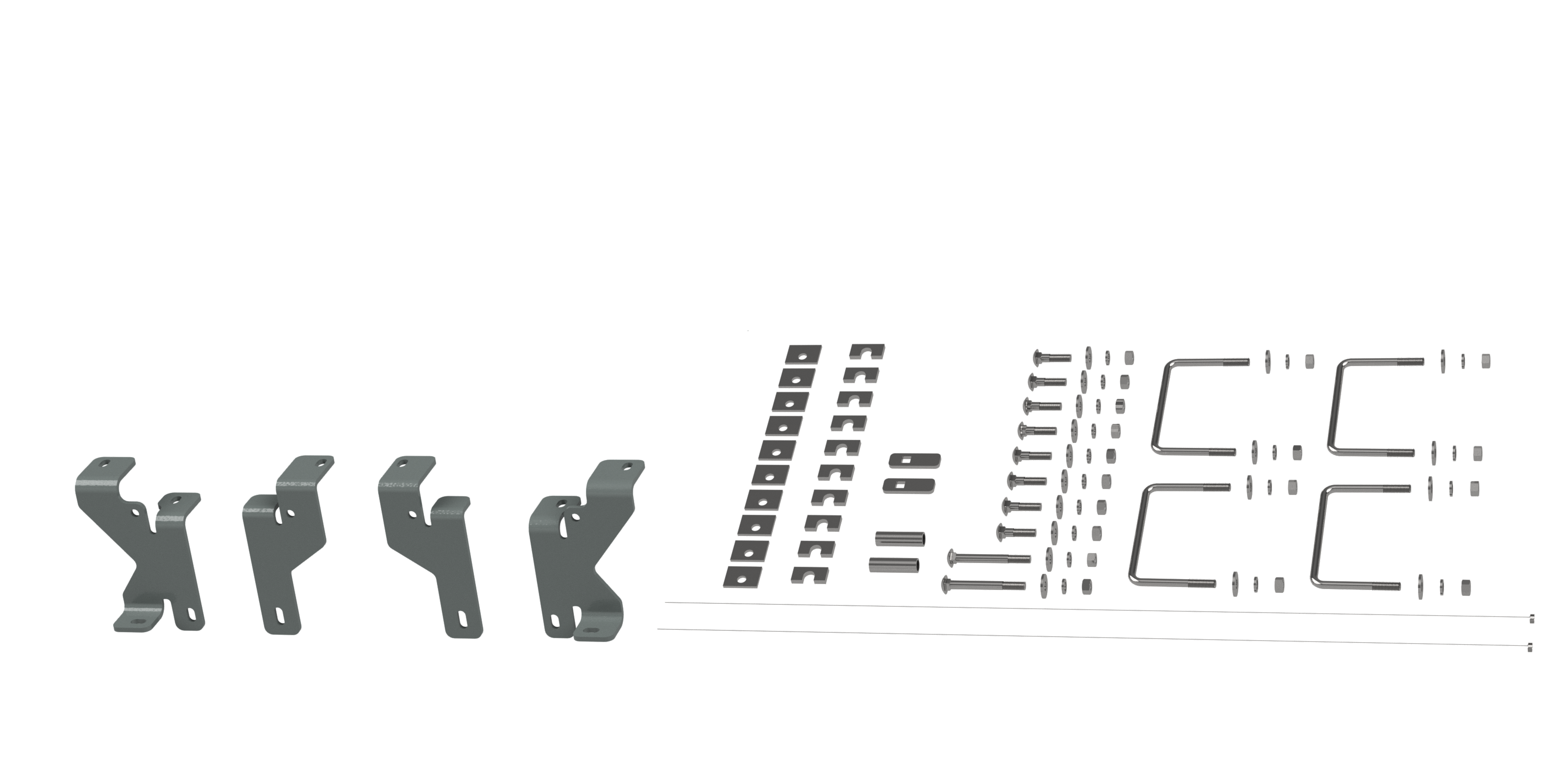
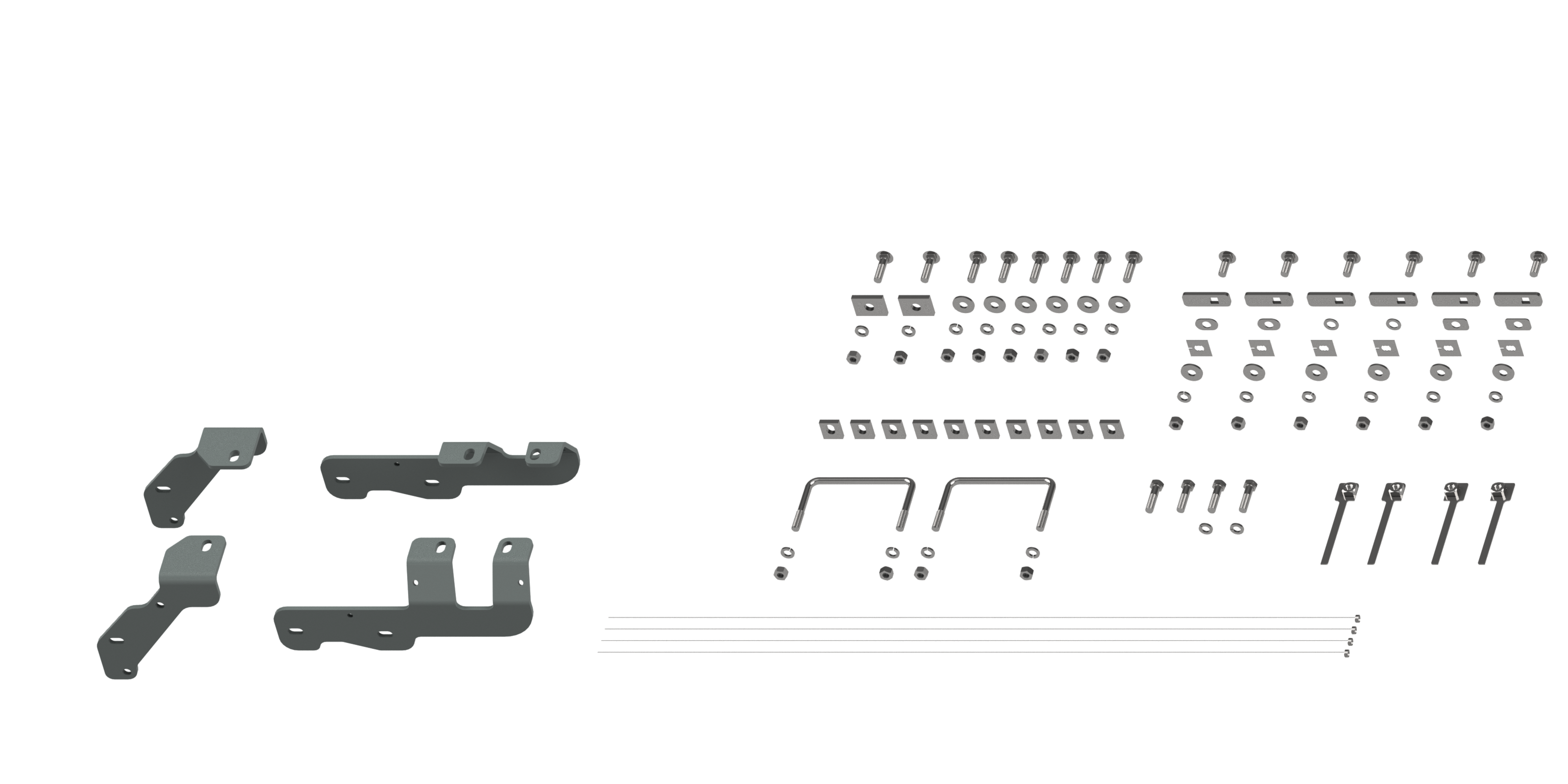
The bracket set (RVR2604) includes: 4 front and rear side plates, 4 nut guides, 2 U-bolts (1/2" x 6–1/4" x 4"), 4 fish wires, 8 carriage bolts (1/2" x 2"), 6 carriage bolts (1/2" x 1–1/2"), 4 cap screws (1/2" x 2"), 12 flat washers (1/2"), 20 split lock washers (1/2"), 18 finish nuts (1/2"), 2 spacers (2" x 1–1/2" x 5/16"), 10 offset spacers (5/16" thick), 6 locking straps, 6 bolt retainers, 2 oval frame spacers, 2 circle frame spacers, and 2 rectangle frame spacers.
After installing the rear side plates and drilling the 9/16" holes in the bed, check that the 1/8" pilot holes are aligned front to back in the center of the slots in the two rear side plate flanges. If the 1/8" drill holes cannot be centered within the slots, re-drill the 1/8" holes until the side plates and drilled holes can be properly aligned. This ensures the mounting rail will sit correctly.
The nut guides must be prepared by putting a 60° bend in the handle approximately 3–3/4" from the top. This bend allows the nut guide to be positioned under the 9/16" holes in the bed cross member for the two outside rear bolt locations on the forward mounting rail, where access from underneath is not possible.
Pass the nut on the nut guide through the vertical slot on the end of the bed cross member and turn it so the nut is on the bottom of the guide. Hold the nut under the 9/16" hole while a 1/2" x 2" cap screw with a 1/2" lock washer is passed down through the forward mounting rail from the top of the bed and threaded into the nut guide by another person. This two-person procedure is necessary because the bed cross member blocks access from underneath.
Orient the front side plate so the flange is up and toward the truck. Angle the flange between the frame and the bed. Align the side plate so that the U-bolt and the 1/2" carriage bolt in the frame pass through the holes in the side plate. The slot in the flange should be centered front to back in the 9/16" hole in the bed. Push the side plate up against the bottom of the truck bed while hand tightening the three nuts.
The manual does not specify whether the battery must be disconnected. However, the manual does note that wiring connections may need to be loosened or detached during installation of the rear side plates, and that any wiring moved or detached must be re-secured after installation. Consult the truck manufacturer's guidance or a professional installer if you are uncertain about electrical safety during this installation.
The RVK2604 fits 2019–2025 Ram 1500 trucks only. It excludes RAM 1500 Classic, RAM TRX, and beds with gussets on the front end of the bed rails.
You need an impact wrench or ratchet with 3/4" socket, 3/4" box end wrench, drill with 1/8" and 9/16" bits, tape measure, torque wrench, center punch, hammer, flashlight, and eye and ear protection.
Yes. Some assembly steps require two people, particularly when installing nut guides and cap screws on trucks with four-corner air suspension or when positioning the forward mounting rail.
Yes. You must drill five 1/8" pilot holes and then enlarge them to 9/16" for both the rear and forward mounting rail locations. The hole pattern differs based on your truck's suspension type (coil spring or four-corner air).
Torque all 1/2" nuts and cap screws in the mounting rails and side plates to 80 ft. lbs. using a torque wrench.
Before each tow, visually inspect the hitch, verify all pinned and bolted connections are secure and at 80 ft. lbs. torque, and check for cracks or damage. Do not tow if damage is found.
Yes, the RVK2604 can be installed over a spray-in bed liner. However, you must account for the liner thickness when measuring and marking hole locations. Removable bed liners must be removed.
Check that the rear side plates are flat against the frame and that the two flanges on top are flat against the bottom of the bed. If the 1/8" pilot holes cannot be centered within the slots in the flanges, re-drill the 1/8" holes until the side plates and drilled holes can be properly aligned. This will allow the flanges to sit flat.
The locking strap and bolt must pass through the frame separated, not with the bolt through the square hole in the strap. If they are together, the bolt will hang up inside the frame. Ensure the locking strap is passed onto the fish wire separately from the bolt, and push the locking strap completely into the frame before pulling the bolt through.
The spacer must be inside the frame hole and not stick past the face of the frame. If it is protruding, you have not pushed it far enough into the hole. Push the frame spacer completely into the hole so it is flush with or recessed from the frame face.
While carefully ensuring the mounting rail does not move, use a center punch tool to mark the five drill locations. It is critical that the five drill locations be marked exactly in the center of the square hole in the rail. If the rail is moving, ensure you are holding it firmly in place or have a second person stabilize it while you mark the holes.
Pass the U-bolt up between the fuel tank and the frame, not over the fuel tank. Ensure the threaded ends of the U-bolt are toward the rear of the truck. When the leg of the U-bolt passes the top of the frame, rotate the legs toward the outside of the frame. If the U-bolt still interferes with the fuel tank, check that you are not installing it in the wrong location.
On trucks with four-corner air suspension, the two outside rearward holes are not accessible from underneath due to air tanks. Use 1/2" x 2" cap screws with nut guides instead of carriage bolts for these two positions. Position the nut guide under the 9/16" hole and thread the cap screw down through the mounting rail into the nut guide from above.
With the base still attached to the forward rail, ensure that the forward rail is centered in the truck bed by measuring the distance from each side of the bed to the edge of the rail; both measurements should be equal. If it is not centered, reposition the rail and base until it is centered before drilling the hole locations.

Total for 2 items:
$260.00
Free Shipping
Ships free on all orders
 Authorized Dealer


Quick Ship
In stock and ready to ship — order now!
FREE ShippingFREE SHIPPING
Estimated delivery Sun, Aug 9 - Wed, Aug 12
Order before 2 PM EST Monday–Friday for same-day processing
Guaranteed safe & secure checkout
No reviews have been added for this product.