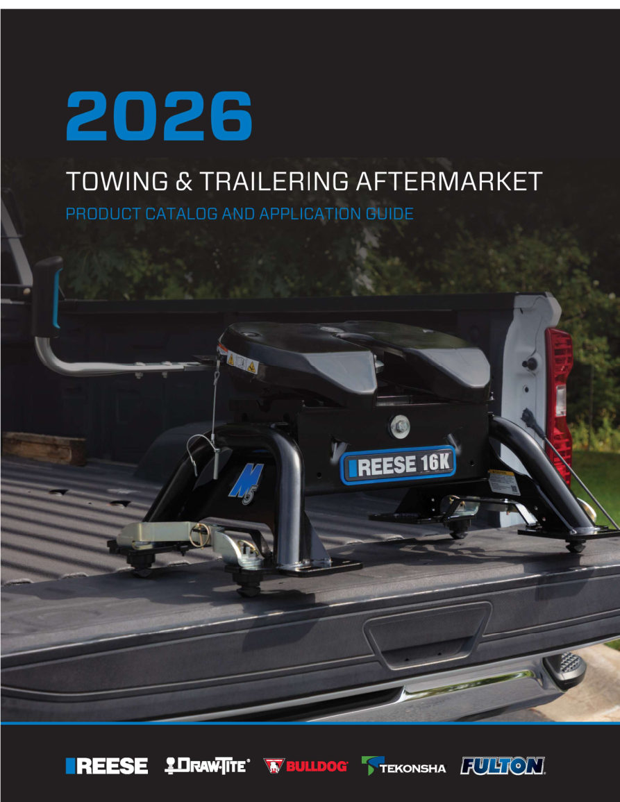
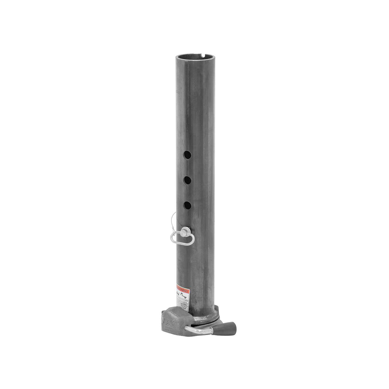
Bulldog BX1 Gooseneck Coupler, 2-5/16 in. Diameter, 25,000 lbs. Capacity, Round BD1289000300Bulldog$257.36Out of Stock
View productOur in-house experts typically reply within one business day.

Bulldog
Free Shipping
Ships free on all orders
 Authorized Dealer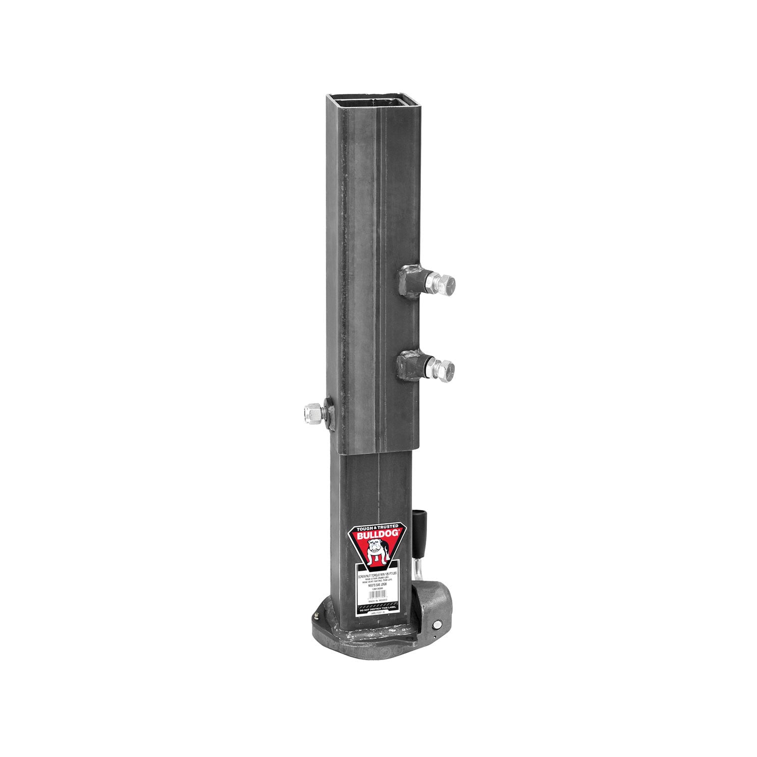


Always the correct part
We know our products
Quality Products
Free Shipping!
Always the correct part
We know our products
Quality Products
Free Shipping!
FREE ShippingFREE SHIPPING
Estimated delivery Sun, Sep 27 - Wed, Sep 30
Order before 2 PM EST Monday–Friday for same-day processing
Guaranteed safe & secure checkout

The BULLDOG BX1 coupler is the result of generations of design expertise and field experience. It incorporates innovative features that revolutionize the benefits available from a gooseneck coupler.
| BRAND: | BULLDOG |
| PART NUMBER: | 1289020300 |
| WARRANTY: | LIMITED 5 YEAR WARRANTY |
| WEIGHT: | 30.4 LBS |
| CAPACITY: | 25,000 LBS. |
| BALL DIAMETER: | 2.313 IN. |
| MATERIAL: | STEEL |
| HITCH CLASS: | V |
| SAFETY CHAINS INCLUDED: | NO |

Founded in 1920, Bulldog has become the standard for heavy-duty trailer connection hardware in agricultural, military and utility service. The line covers gooseneck hitches and couplers, A-frame and channel-mount trailer couplers with the Wedge-Latch mechanism, and heavy-duty jacks, built for unmatched strength, reliability and safety under demanding loads.
Bulldog was founded in 1920 and has spent more than a century supplying the connection hardware that heavy trailers depend on. Its market has always been the demanding end: agricultural, military and utility applications where a coupler failure is not an inconvenience but a serious incident. The brand summarises its position as Tough and Tested, and it sits within the Horizon Global towing group alongside Reese, Draw-Tite, Fulton, Tekonsha, Bargman and Wesbar.
Gooseneck equipment is the brand's signature. Gooseneck hitches mount in the truck bed over the rear axle, which places the load where the chassis can carry it properly and allows far tighter turning than a receiver hitch permits. Matching gooseneck couplers attach at the trailer end, in round tube and square configurations across the capacity range used by livestock, equipment and flatbed trailers.
The conventional trailer coupler range is built around the Wedge-Latch mechanism, which uses a wedge to take up wear between coupler and ball rather than relying on a fixed clamp that loosens over time. That matters on a trailer accumulating hard miles, where slack in the coupling shows up as noise and shock loading. Couplers are offered in A-frame form for standard tongues and in channel-mount form for straight tongue and fabricated frames, with adjustable channel versions that let a coupler be positioned to suit the tongue height.
Heavy-duty jacks complete the line, sized for the tongue weights that gooseneck and equipment trailers generate. Across the range the emphasis is consistent: forged and heavy-section components, load ratings backed by testing, and hardware specified for agricultural, military and heavy-duty commercial use rather than occasional recreational towing.
Experts available to answer your questions
Call 888-634-94945 Years
BULLDOG® BX1 Gooseneck Coupler
The Bulldog BX1 is a gooseneck coupler designed to connect a gooseneck trailer to a towing vehicle via a 2 5/16" hitch ball. It features a load bearing pin, retaining pin, locking mechanism, and theft deterrent lock hole. The coupler is rated according to SAE J2638 and must support its rated load with the load bearing pin fully inserted through both inner and outer tubes.
The coupler requires a 2 5/16" hitch ball rated equal to or greater than the capacity of the coupler. The ball rating must match or exceed the coupler's rated capacity. Refer to the stamped markings or decals on the coupler to determine its rated capacity.
All hardware, including set bolts and jam nuts, must be torqued to 125 ft-lbs minimum. Periodically check for proper torque and retighten if necessary. Check for wear on the inner tube if retightening is needed.
All welding must be performed by an AWS (American Welding Society) certified welder. The coupler must be rigidly attached to the trailer via gussets. The manual does not specify whether other aspects of installation require professional installation, but the welding requirement is mandatory.
The maximum extension is 8" measured as the difference between the fully retracted and fully extended positions. Do not exceed this maximum extension. Couplers with properly installed load bearing pins and square adjustable gooseneck couplers only extend within this range.
No. Do not tow unless the load bearing pin is fully inserted through both the inner and outer tubes and the retaining pin is installed. The coupler cannot support its rated load without the load bearing pin fully inserted.
Before towing, check the vehicle, hitch ball, and coupler for signs of wear or damage. Ensure the coupler opens, closes, and the handle springs closed when released. Verify the hitch ball is fully seated in the coupler ball pocket and the latch is closed. Ensure trailer safety chains are properly connected and all trailer lighting is hooked up and working. Always replace bent, broken, or worn parts before using the product.
Maintenance procedures should be performed at least annually: check hardware torque, grease all fittings and ball pocket, and inspect the retaining pin and replace if necessary. Keep the ball pocket, latch, and handle clean at all times.
The manual does not specify vehicle or trailer compatibility. It states that weld size, gusseting requirements, coupler height, and orientation are dependent on trailer design and customer requirements. The coupler must be rigidly attached to the trailer via gussets. Contact Cequent Performance Products at 1-800-521-0510 or visit www.cequentgroup.com to confirm fitment for your specific trailer.
Before mounting the coupler, you must confirm that there will be no interference from the tow vehicle, tongue, ground, and any other mounted accessories while stationary or in motion. Check for interference in both extended and retracted positions before installation, and check again after installation is complete. If interference is found, do not use the coupler.
The manual does not specify tools required for the initial coupler installation. However, if you need to replace the handle using the available handle repair kit, you will need a hammer and 5/32" punch. For the full installation, you will need welding equipment and an AWS certified welder, plus tools to attach gussets to the trailer frame.
Yes. The coupler must be rigidly attached to the trailer using gussets (reinforcement plates). The manual states that all welding must be performed by an AWS certified welder. Avoid heat damage to the coupler during welding and do not weld over or near any holes or hardware on the coupler. Weld size and gusseting requirements depend on trailer design and customer requirements.
Yes. The coupler must be welded to the trailer frame using gussets (reinforcement plates) that extend down the outer tube to within 3" above the bottom of the outer tube. This is a permanent welded attachment. The coupler must be held rigid and vertical, and must not be damaged by heat during installation. These modifications cannot be reversed.
The rated capacity is stamped on the coupler or shown on decals. Refer to the stamped markings or decals on the product to obtain the rated capacity. If uncertain, contact Cequent Performance Products at 1-800-521-0510 or www.cequentgroup.com. Do not exceed the lesser of the coupler, hitch, vehicle, ball, or trailer weight ratings (including load).
The maximum extension is 8" measured as the difference between the fully retracted position and the fully extended position. Do not exceed this maximum. Measure the coupler extension by comparing the distance from the fully retracted to fully extended positions.
Reinforcements (gussets) must extend down the outer tube to within 3" above the bottom of the outer tube. This ensures the coupler can support its rated load. The gussets must be attached as low as possible to the outer tube while maintaining this 3" clearance from the bottom.
1. Block the trailer wheels. 2. Align the hitch ball beneath the coupler. 3. Set the coupler into the open position by lifting up on the handle and slide the locking plate into the detent. 4. Lower the trailer onto the hitch ball. 5. Visually check that the hitch ball is fully seated in the coupler. 6. Slide the locking plate over and place the handle down into the closed position. When using a recessed ball, check that the handle and locking plates are clear of interference with safety chains and D-rings. 7. Insert the optional theft deterrent lock through the hole in the fixed plate.
1. Block the trailer wheels. 2. Remove the lock (if equipped) and set the handle into the open position. 3. Slide the locking plate into the open position and raise the trailer from the hitch ball.
Yes. The set bolts must be facing the towing vehicle. This is a required orientation for proper installation.
Yes. The coupler must remain vertical after installation to ensure proper operation. If the coupler is not vertical, its operation may be impaired and it should not be used.
Do not exceed the lesser of the coupler, hitch, vehicle, ball, or trailer weight ratings (including load). Weigh your trailer plus added load before towing. Refer to the stamped markings or decals on the coupler to obtain its rated capacity. If uncertain about any component's rating, contact Cequent Performance Products at 1-800-521-0510 or www.cequentgroup.com.
Always block the trailer wheels before latching or unlatching the coupler. Always secure the load, vehicle, and trailer (by blocking wheels) before latching/unlatching. Never position any body part under any portion of the coupler or the load being supported. Do not allow children to play on or around the coupler or the load being supported.
Before towing, check the vehicle, hitch ball, and coupler for signs of wear or damage. Ensure the coupler opens, closes, and the handle springs closed when released. Verify the hitch ball is fully seated in the coupler ball pocket and the latch is closed. Ensure trailer safety chains are properly connected to the towing vehicle and trailer. Verify all trailer lighting is hooked up and working properly. Always replace bent, broken, or worn parts before using the product.
After installation is complete, check for interference again in both extended and retracted positions. Verify that the coupler operation has not been impaired in any way. The coupler must remain vertical. After assembly and painting, but prior to being used, any enclosed labels must be affixed to the coupler and premask removed. Do not use the coupler if its operation has been impaired.
Keep the ball pocket, latch, and handle clean. At least annually, perform the following: check hardware torque (must be 125 ft-lbs minimum), grease all fittings and ball pocket, and inspect the retaining pin and replace if necessary. Periodically check for proper torque and retighten if necessary. Check for wear on the inner tube if retightening is needed.
A handle repair kit is available to replace worn or malfunctioning parts. This kit includes the handle assembly, locking cam, groove pin, bushing, and torsion spring. Use only Cequent Performance Products' parts or parts of equal quality for repair. Replacement parts are available through Cequent Performance Products' Customer Service Department at 1-800-521-0510. Please specify the product model number.
Required tools: hammer and 5/32" punch. 1. Loosen set bolts, remove the load bearing pin, and lower the coupler assembly from the trailer. With the ball pocket facing up, note the parts and their orientation, paying particular attention to the handle and locking cam function. 2. Rotate the handle to expose the groove pin. With a punch, remove the groove pin and slide the handle from the coupler. Remove and discard all old parts. Do not reassemble using any previously existing parts—only use components supplied in the parts kit. 3. Place the bushing within the coupler body. Assemble the straight leg side of the torsion spring into the locking cam and lower it into the casting. Ensure the cam lobe notch rests against the inside edge of the coupler casting. 4. Insert the bent-leg end of the spring into the bushing side of the casting and slide the handle through the assembled parts. 5. Align the hole in the handle with the hole in the cam and fix the groove pin into place. A properly assembled handle will make a loud "clack" from open to closed position when the locking cam hits the coupler casting.
The Bulldog BX1 has a Limited Five Year Warranty. Cequent Performance Products warrants to the original consumer purchaser only that the product will be free from material defects in both material and workmanship for five years, ordinary wear and tear excepted, provided that installation and use of the product is in accordance with product instructions. The warranty does not cover normal wear and tear, damage from abuse, neglect, misuse, accidents, misapplication, overloading, improper installation (including welds), improper maintenance and repair, or product alteration by anyone other than the manufacturer. This warranty is not transferable. To make a warranty claim, contact Cequent Performance Products at 47774 Anchor Ct. W., Plymouth, MI 48170, 1-800-521-0510, identify the product by model number, and follow the claim instructions provided. You must provide the product and purchase receipt to process a warranty claim.
No. The purchaser/owner must not alter or modify the product. Any modifications made by anyone other than the manufacturer (except alterations made pursuant to product instructions and in a workmanlike manner) will void the warranty and may result in coupler failure or unsafe operation.
The coupler includes an optional theft deterrent locking hole in the fixed plate. You can insert an optional theft deterrent lock through this hole to help prevent unauthorized uncoupling. This is an optional security feature and the lock is not included with the coupler.
Do not use the coupler if its operation has been impaired in any way. Check the coupler to ensure it opens, closes, and the handle springs closed when released. If any of these functions are not working properly, do not tow. Contact Cequent Performance Products at 1-800-521-0510 for repair or replacement options.
The handle should spring closed when released. If it does not, the coupler operation is impaired. Do not use the coupler for towing. The handle assembly may need repair or replacement. A handle repair kit is available that includes the handle assembly, locking cam, groove pin, bushing, and torsion spring. Contact Cequent Performance Products at 1-800-521-0510 for repair or replacement options.
If the coupler does not open or close properly, its operation is impaired. Do not use the coupler for towing. Check that the ball pocket, latch, and handle are clean and free of debris. If cleaning does not resolve the issue, the coupler may require repair or replacement. Contact Cequent Performance Products at 1-800-521-0510 for service options.
If hardware requires frequent retightening, check for wear on the inner tube. Excessive wear on the inner tube could be causing the hardware to loosen. If wear is detected, the worn components should be inspected and replaced if necessary. Ensure all hardware is torqued to 125 ft-lbs minimum. If the problem persists after retightening and inspection, contact Cequent Performance Products at 1-800-521-0510.
The coupler must remain vertical after installation to ensure proper operation. If the coupler is not vertical, its operation may be impaired and it should not be used. Check the gusset attachment and trailer frame alignment. The coupler may need to be repositioned or the gussets may need adjustment. Do not use the coupler until it is properly vertical. Contact Cequent Performance Products at 1-800-521-0510 if repositioning is not possible.
Before mounting the coupler, confirm that there will be no interference from the tow vehicle, tongue, ground, and any other mounted accessories while stationary or in motion. Check for interference in both extended and retracted positions. If interference is found, do not use the coupler. The coupler may need to be repositioned, or the interfering components may need to be relocated or modified. Contact Cequent Performance Products at 1-800-521-0510 for guidance on resolving interference issues.
Do not exceed the 8" maximum extension from the fully retracted position. If the coupler extends beyond 8", it is not operating within its design specifications and may not properly support the rated load. Measure the extension as the difference between the fully retracted and fully extended positions. If the extension exceeds 8", the load bearing pin may not be properly installed, or the coupler may be damaged. Verify the load bearing pin is fully inserted and the retaining pin is installed. If the problem persists, contact Cequent Performance Products at 1-800-521-0510.
| Part Number | Description | Capacity (lbs.) | Retracted Height (in.) | Extended Height (in.) | Adjustment (in.) | Ball Size |
|---|---|---|---|---|---|---|
| 1289030030 | BX1 Coupler, 4.5 in. Diameter x 20 in. Length Outer Tube, 4 in. Diameter x 27.2 in. Inner Tube, with BX1 Cast Coupler Head, 3/4 in. Load Bearing Pin, (2) Set Bolts, Raw, Labels Applied | 20,000 | 27.50 | 35.50 | 8.00 | 2-5/16 |
| 1289003030 | BX1 Adjustable Gooseneck Coupler, 4.5 in. Diameter x 20 in. Length Outer Tube, 4 in. Diameter x 27.2 in. Inner Tube, with BX1 Cast Coupler Head, 3/4 in. Load Bearing Pin, (2) Set Bolts, Raw, Labels Applied | 25,000 | 27.50 | 35.50 | 8.00 | 2-5/16 |
| Short Configuration | ||||||
| 1289070300 | BX1 Coupler, 4.5 in. Diameter x 20 in. Length Outer Tube, 4 in. Diameter x 22.2 in. Inner Tube, with BX1 Cast Coupler Head, 3/4 in. Load Bearing Pin, (2) Set Bolts, Raw, Labels Loose | 20,000 | 22.60 | 30.60 | 8.00 | 2-5/16 |
| 1289040300 | BX1 Coupler, 4.5 in. Diameter x 20 in. Length Outer Tube, 4 in. Diameter x 22.2 in. Inner Tube, with BX1 Cast Coupler Head, 3/4 in. Load Bearing Pin, (2) Set Bolts, Raw, Labels Loose | 30,000 | 22.60 | 30.60 | 8.00 | 2-5/16 |
| Inner Tube Only | ||||||
| 1289020300 | BX1 Coupler, 4 in. Diameter x 27.2 in. Inner Tube Only, with BX1 Cast Coupler Head, Raw, Labels Loose | 25,000 | - | - | - | 2-5/16 |
| 1289050300 | BX1 Coupler, Short Configuration, 4 in. Diameter x 22.2 in. Inner Tube Only, with BX1 Cast Coupler Head, Raw, Labels Loose | 30,000 | - | - | - | 2-5/16 |
| Replacement Parts | ||||||
| 500356 | BX1 Gooseneck Coupler 5/16 in. Locking Pin | - | - | - | - | - |
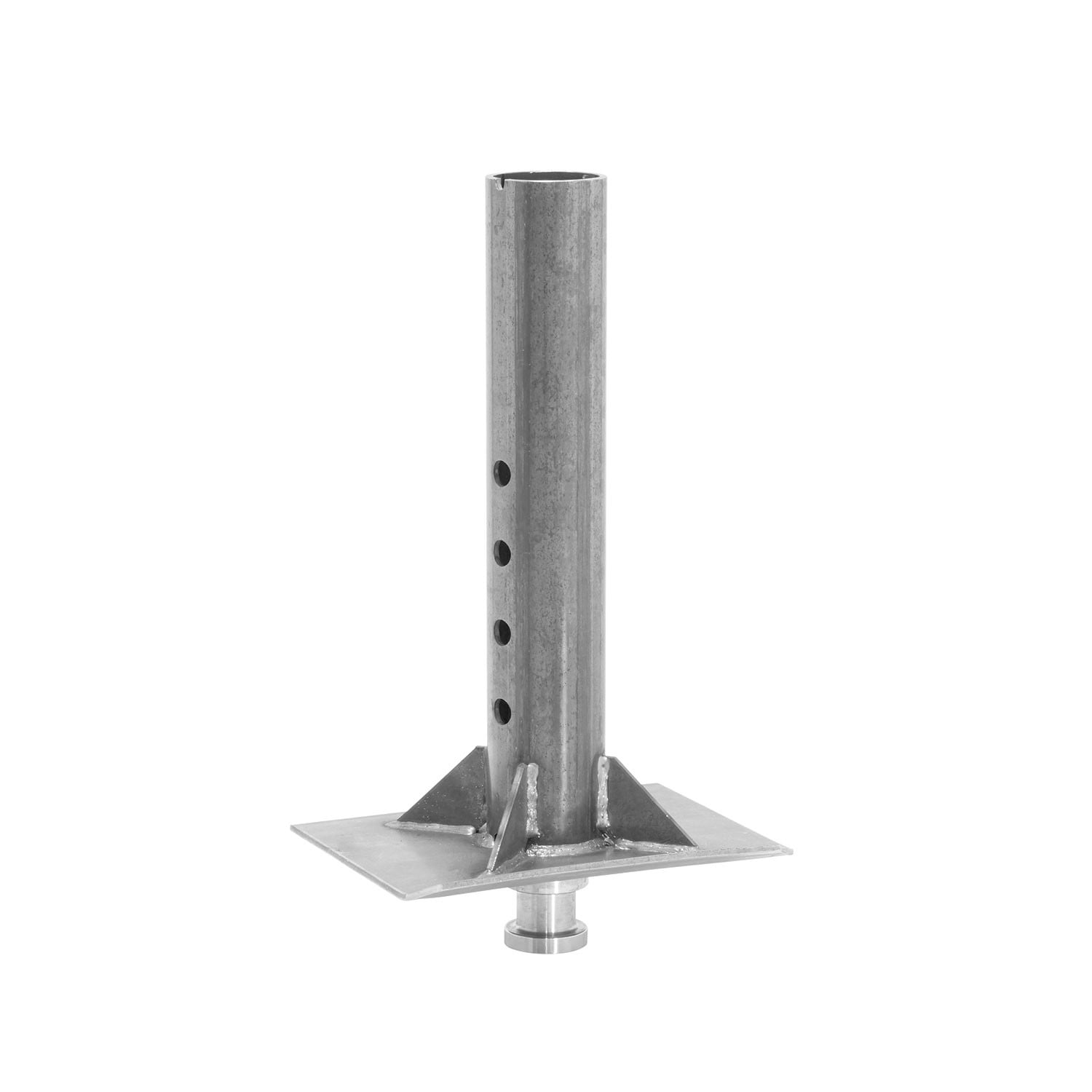
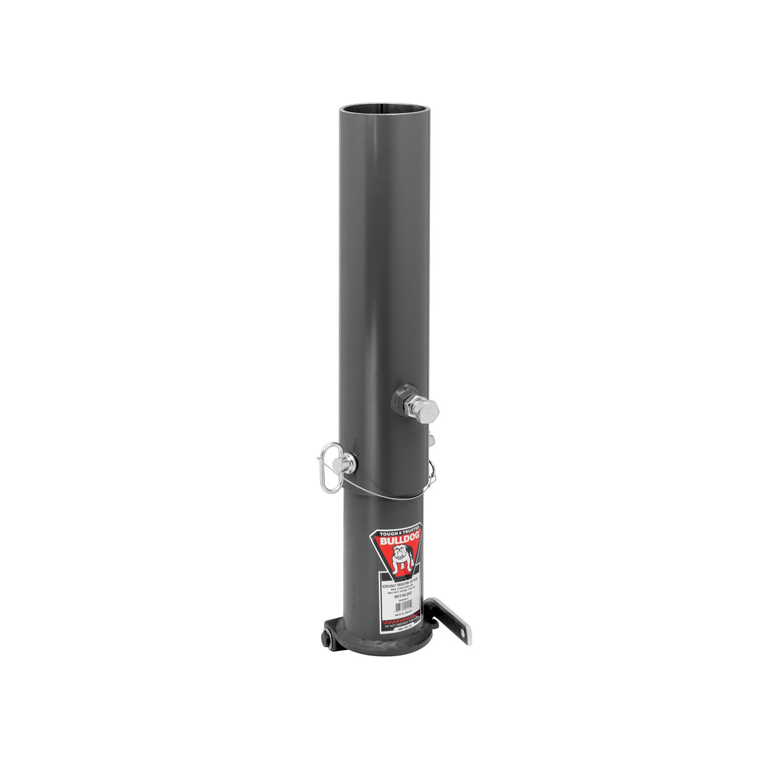
| 5203310030 | BX1 Gooseneck Coupler Outer Tube, 4.5 in. Diameter x 20 in. Length, Hole for 3/4 in. Load Bearing Pin, (2) Set Bolts | - | - | - | - | - |
Sam
The staff was able to quickly assist me with locating the correct product I needed. Shipping was really fast. Item arrived in 2 days. Will be using TowUniverse again!!
May 22, 2023