
CURT 60705 38K GTW, 9.5K Vertical PowerHaul Double Lock Gooseneck Hitch, Fits Ram 2500/3500CURT$599.95In Stock
View productOur in-house experts typically reply within one business day.

CURT
Verify Fitment
Select your vehicle to confirm this part fits.
2017 - 2027 Ford F-250 Super Duty
Confirmed to Fit


Always the correct part
We know our products
Quality Products
Free Shipping!
Always the correct part
We know our products
Quality Products
Free Shipping!

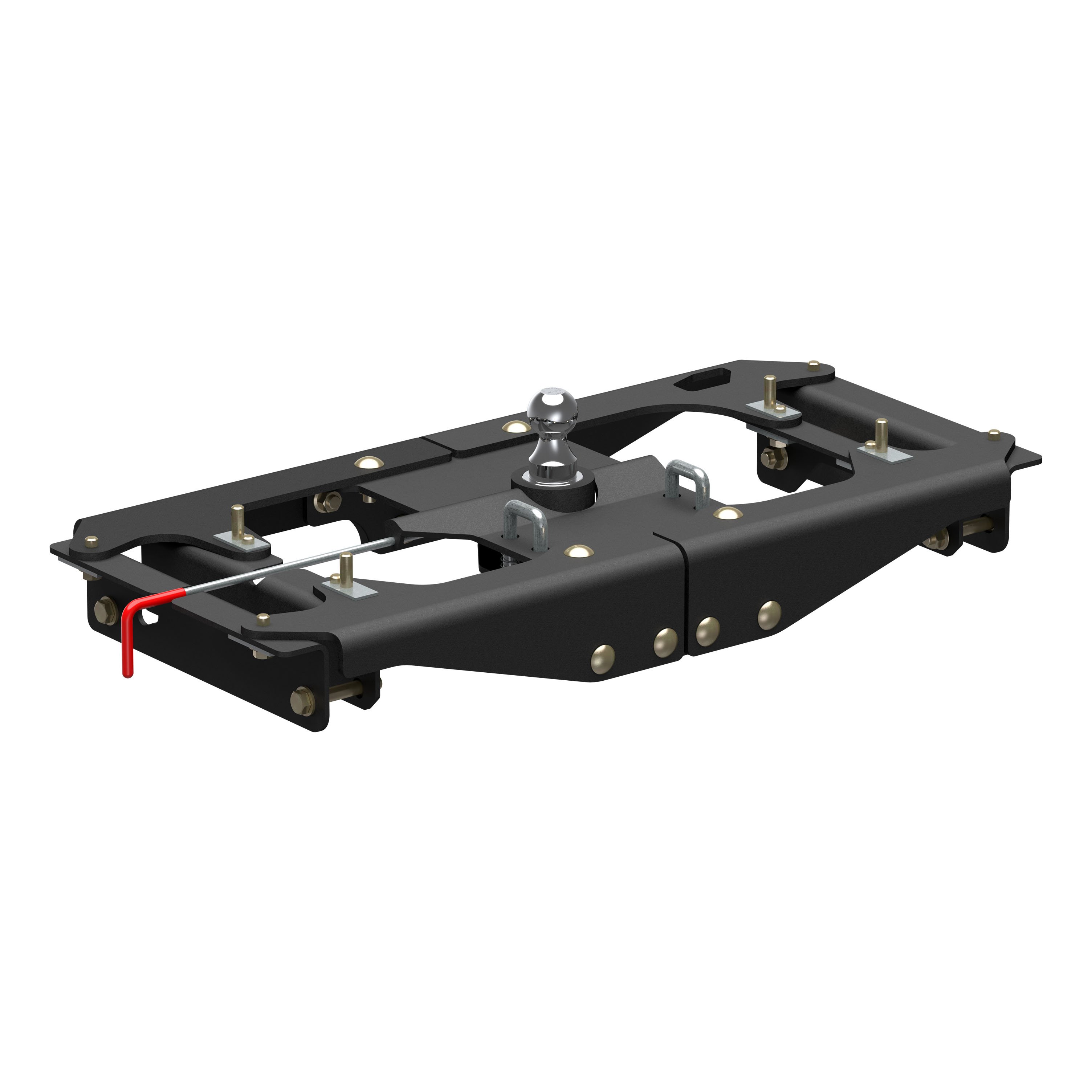
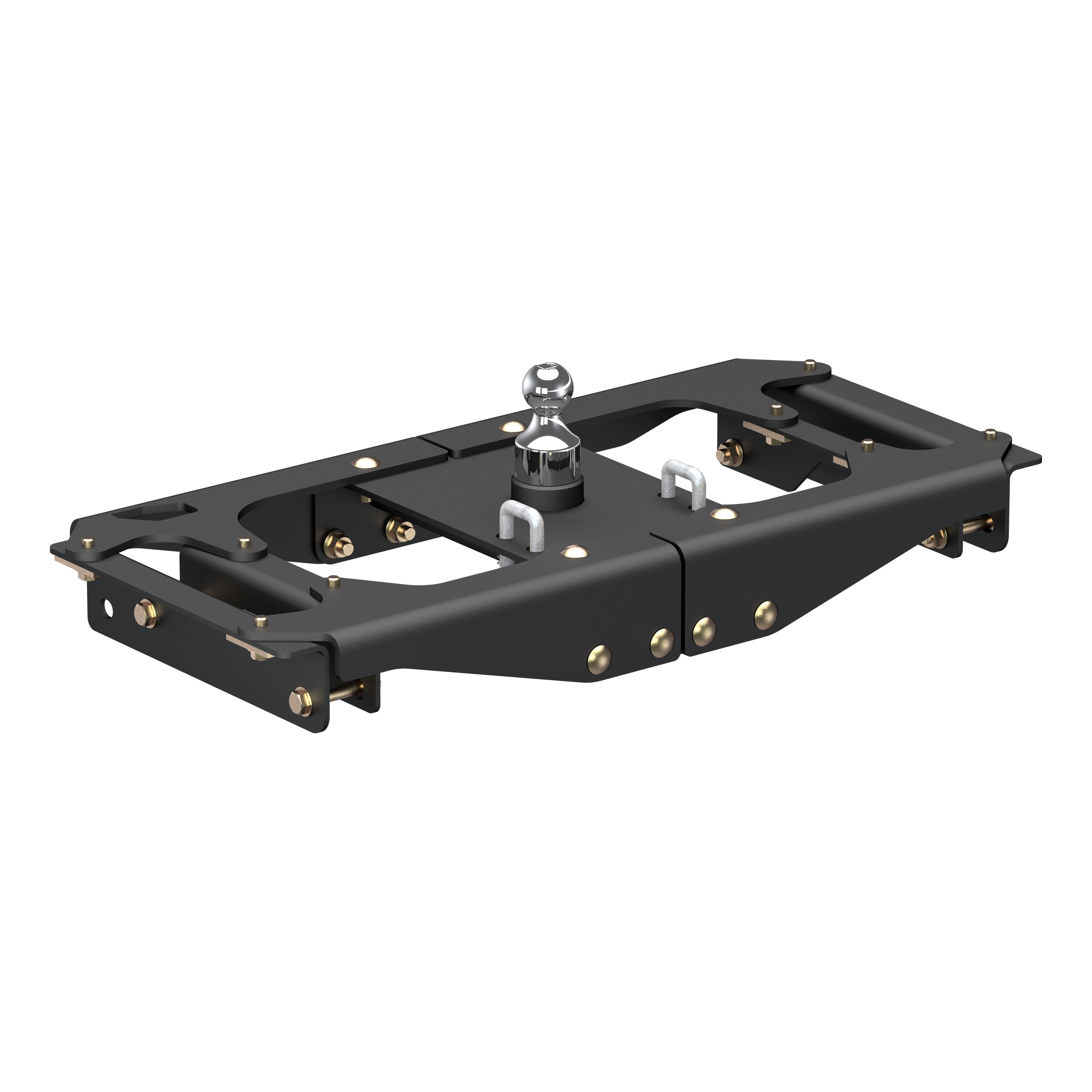
Up to 38,000 lbs. GTW / 9,500 lbs. vertical load with included 2-5/16" ball
| Ball Diameter | 3 IN |
| Gooseneck Hitch Type | Double-Lock Hitch |
| Gross Trailer Weight (GTW) | 38,000 LB |
| Vertical Load Capacity | 9,500 LB |
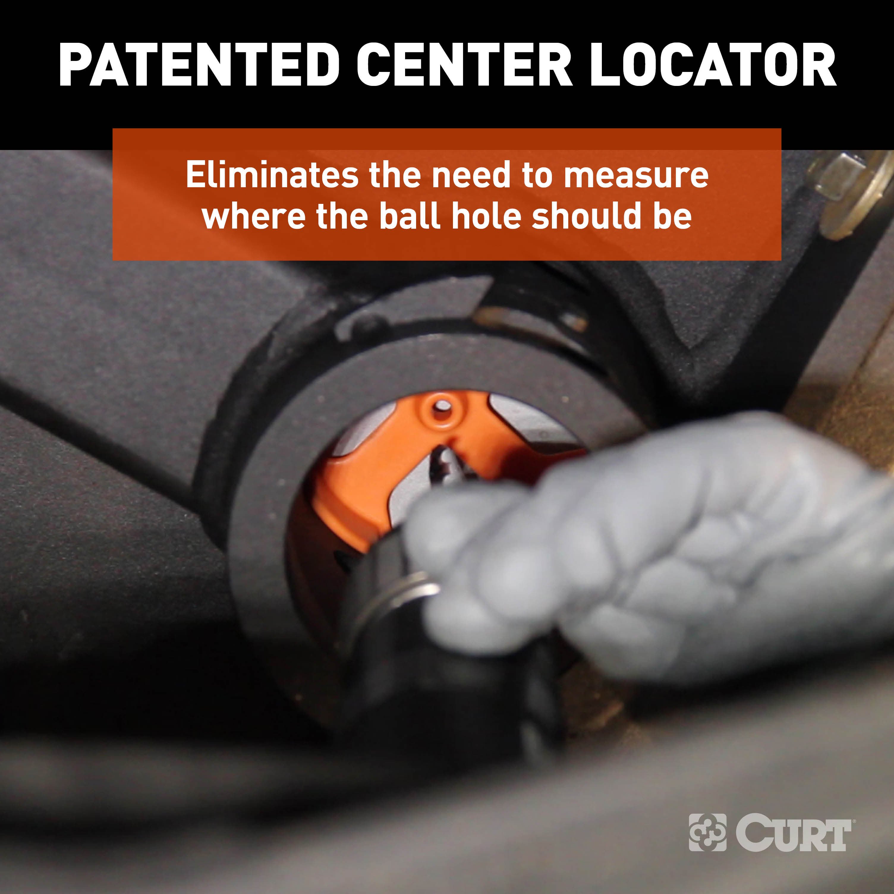
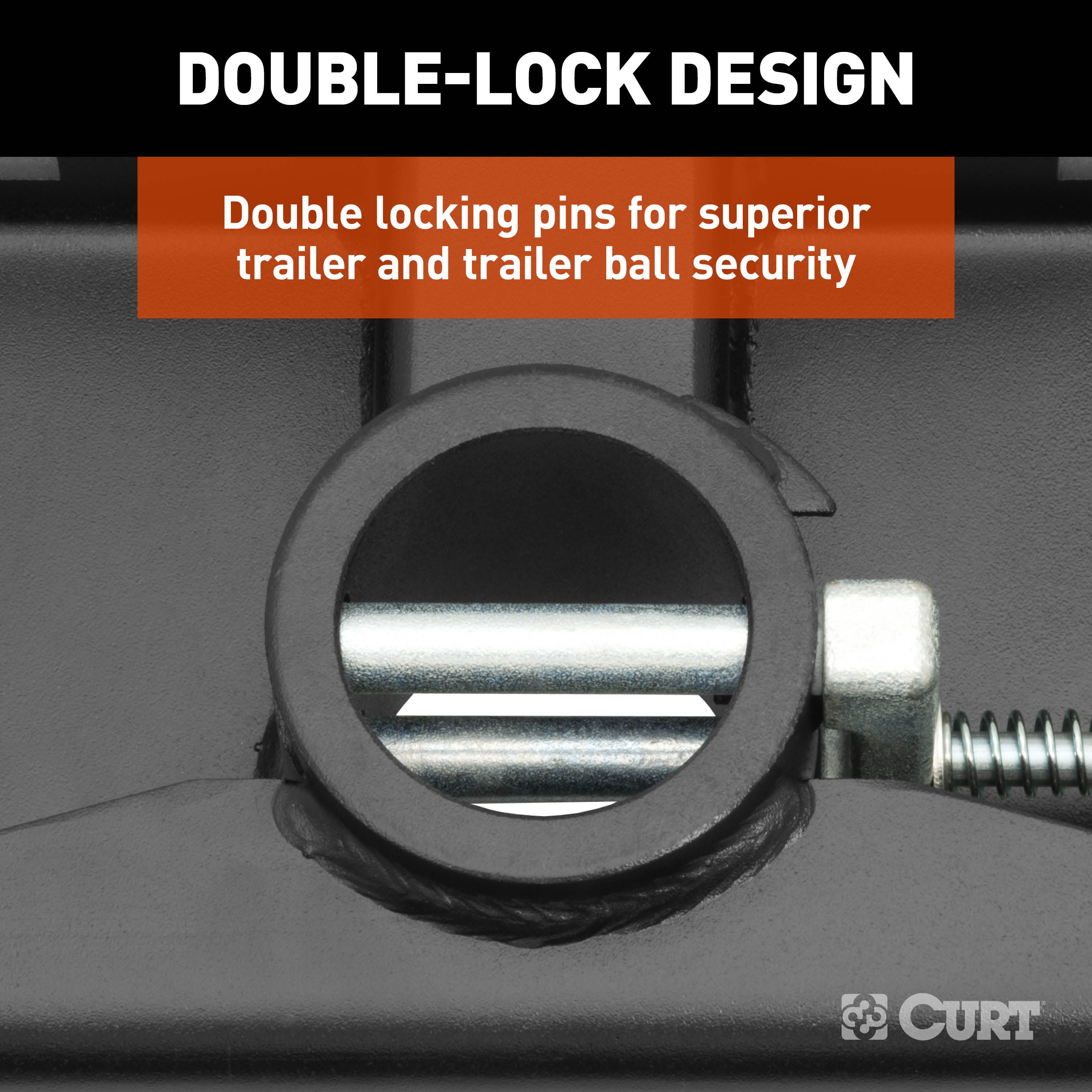
Experience powerful, reliable towing with the CURT PowerHaul™ Double Lock Gooseneck Hitch. Built for both professional haulers and weekend adventurers, this hitch delivers heavy-duty performance, making every towing job safer, smoother, and more controlled. Capable of handling up to 38,000 lbs. GTW and 9,500 lbs. vertical load with the included 2-5/16" ball and up to 40,000 lbs. GTW and 10,000 lbs. vertical load when paired with the optional 3" ball (#60694), the PowerHaul is ready for heavy trailers, construction equipment, and livestock transport. Installation is simple and designed for a single person, requiring no lowering of exhaust or spare tire, no welding, and no bed removal. The center locator system guarantees precise ball placement, so every hitching operation is safe, accurate, and worry-free. Security and convenience are at the forefront of the design. Double locking pins protect both the trailer and the ball, while the removable flip-and-store ball frees up truck bed space for gear, tools, or recreational equipment. The heavy-duty 3/8" handle and spring-loaded 5/8" safety chain loops provide dependable, long-lasting performance on every journey. Built to last, the PowerHaul meets SAE J2638 safety standards, features a rust-resistant liquid A-coat finish, and is proudly designed, welded, and coated in Wisconsin. With a limited lifetime warranty (one year on finish and parts), this double-lock gooseneck hitch gives you the strength and confidence to take on your toughest towing projects, whether you’re hitting the job site, transporting livestock, or cruising the open road with your trailer in tow.

CURT offers a variety of high-quality trailer hitches and accessories for select vehicle models. Find the perfect fit for your towing needs at TowUniverse.
CURT, a Lippert brand, offers a complete line of towing products and is the leading manufacturer of custom-fit trailer hitches. We offer the broadest selection of custom-fit hitches, and each one is designed, welded, and coated in Wisconsin.
CURT is also a leader in flat towing products, as well as 5th wheel, gooseneck, and weight distribution hitches, ball mounts, electrical components, cargo solutions, and other towing accessories.
For everything from passenger cars and vans to full-size pickups and SUVs, CURT is 'The First Name in Towing Products®.'

Experts available to answer your questions
Call 888-634-9494Limited lifetime warranty (one-year finish, one-year parts)
Rediscover "Us" Time | Tested. Proven. Safe. Towing Products
6 compatible vehicles
| Year | Make & Model | Style | Notes |
|---|---|---|---|
| 2017 - 2027 | Ford F-250 Super Duty | — | — |
| 2017 - 2027 | Ford F-350 Super Duty | Crew Cab Pickup | — |
| 2017 - 2027 | Ford F-350 Super Duty | Extended Cab Pickup | — |
| 2017 - 2027 | Ford F-350 Super Duty | Standard Cab Pickup | — |
| 2017 - 2026 | Ford F-450 Super Duty | Crew Cab Pickup | — |
| 2019 - 2026 | Ford F-450 Super Duty | Standard Cab Pickup | — |
Yes, the CURT 60703 38K PowerHaul Double Lock Gooseneck Hitch for Ford F-250, F-350, F-450, 38K GTW, 9.5K Vertical Load (Part #BKDK60703) is designed to fit the 2017-2026 Ford F-250 Super Duty.
The CURT 60703 38K PowerHaul Double Lock Gooseneck Hitch for Ford F-250, F-350, F-450, 38K GTW, 9.5K Vertical Load (Part #BKDK60703) fits 2017-2026 Ford F-250 Super Duty models. The 2026 model year is the last year covered by this part number. For newer models, check for an updated version.
The CURT 60703 38K PowerHaul Double Lock Gooseneck Hitch for Ford F-250, F-350, F-450, 38K GTW, 9.5K Vertical Load (Part #BKDK60703) fits the following vehicles: 2017-2026 Ford F-250 Super Duty; 2017-2026 Ford F-350 Super Duty; 2017-2026 Ford F-450 Super Duty. Always verify your specific year, make, and model before ordering.
The CURT 60703 38K PowerHaul Double Lock Gooseneck Hitch for Ford F-250, F-350, F-450, 38K GTW, 9.5K Vertical Load (Part #BKDK60703) Refer to the included instructions for installation details. Basic hand tools are typically all you need.
The 60703 is designed for trucks with 2022 and older models, and 2023 and newer models with inner mounting plates welded to the vehicle frame rails. Verify your truck matches one of these configurations before purchasing. For specific vehicle fitment, contact CURT Product Support at 877.287.8634.
Required tools: ratchet, center punch, torque wrench, eye protection, socket extensions (18" total), hole saw (4"), socket set, cutting fluid, drill, rust inhibitor, wrench (8mm), drill bit (13/16"), drill bit (15/16"), and ear protection. Proper tools will improve installation quality and reduce time required.
Removing the spare tire may aid installation but is not required. If you choose to remove it, you must reinstall it after installation is complete (Step 14).
Yes. You must drill a 3/16" pilot hole through the center locator guide from below the truck bed, then drill a 4" hole through the bed using a hole saw (Step 8). You must also drill four 11/16" holes through the heat shield and truck bed for safety chains (Step 9). No frame drilling is required.
Torque all 9/16" fasteners to 150 lbs.-ft. and all 5/8" fasteners to 212 lbs.-ft. (Step 7). Proper torque is essential to prevent damage to the product or vehicle.
Gross trailer weight (GTW): 40,000 lbs. Tongue weight (TW): 10,000 lbs. Never exceed your vehicle manufacturer's recommended towing capacity.
Keep the gooseneck ball, receiver, and trailer coupler lubricated regularly using silicone spray or equivalent to prevent wear and rust. Keep all components free of dirt and foreign debris. Failure to maintain your towing system could result in poor performance and/or catastrophic failure. Periodic inspection should be performed to ensure all mounting hardware remains tight and structural components are secure.
The 60703 includes a 2 5/16" gooseneck ball, center section, frame attachment plates, crossarms, handle rod with locking pin, rubber cover, and comprehensive hardware: 16 serrated flange nuts (5/8"-11), 4 hex head bolts (5/8"-11), 4 flat washers (5/8"), 8 hex bolts (9/16"-12 X 1-1/2"), 8 serrated conical washers (9/16"), 8 square hole spacers (9/16"), 12 carriage bolts (5/8"-11 X 1-3/4"), 4 springs (U-bolt), 8 flat washers (M16), 2 square U-bolts (5/8"), 4 lock nuts (5/8"-18), U-shaped edging (.300"), 4 bolt retainer clips, 4 round hole spacers, 4 hex bolts (9/16"-12 X 2"), 2 flat washers (3/8"), 1 hex bolt (10"-24 X 1-1/4"), 1 nylock nut (#10-24), and 1 compression spring.
The 60703 is supplied with a 2 5/16" gooseneck ball. This ball is used on both 2022 and older models and 2023 and newer models.
The manual states that removing the spare tire may aid installation but is not required. However, on short bed models, you must check for adequate turning clearance between the front of all trailers and the truck cab. If you plan to keep the spare tire installed, verify clearance before towing. The manual also notes that when the ball is in 'stored' position, you should verify the inverted ball will not interfere with the top of the differential when hauling heavy loads, especially on 2-wheel drive models.
The manual states that no lowering of the exhaust is required for installation. However, brake, fuel, and electrical lines may need to be loosened or repositioned to provide clearance for new hardware. During Step 4, the center section is raised between the drive shaft and the exhaust on the passenger side of the vehicle in front of the rear axle. Ensure adequate clearance before proceeding.
Yes. All models require modification or removal of heat shields. The specific modification procedure is not detailed in the manual, but Step 9 requires drilling four 11/16" holes through the heat shield and truck bed for safety chains. Consult the full-color manual at curtmfg.com or contact CURT Product Support at 877.287.8634 for detailed heat shield modification instructions.
The installation is rated as Difficult. Installation difficulty levels are based on time and effort involved and may vary depending on the installer's level of expertise, condition of the vehicle, and availability of proper tools and equipment. Consider whether professional installation is appropriate for your situation.
The installation follows 14 steps: (1) Optionally remove spare tire; (2) Loosely install frame attachment plates (2023+ models only); (3) Install center attachment plates with carriage bolts and retainer clips, loosely install 9/16" hex bolts; (4) Raise center section between drive shaft and exhaust, align and position; (5) Align carriage bolts with rectangular holes, loosely install 5/8" hex flange nuts; (6) Push center section to truck bed bottom, install remaining carriage bolts and flange nuts; (7) Torque all fasteners; (8) Drill 3/16" pilot hole and 4" hole through bed; (9) Drill four 11/16" holes through heat shield and bed for safety chains; (10) Install safety chain U-bolt assemblies; (11) Insert cast lock pin; (12) Insert handle rod; (13) Secure handle with hex head screw and nylock nut; (14) Reinstall spare tire if removed.
The center locator guide must be installed into the center section PRIOR to raising the gooseneck center section into position (Step 4). It serves as a template for drilling the 4" hole through the truck bed (Step 8). You drill a 3/16" pilot hole through the center locator guide from below the bed, then move above the truck and drill the 4" hole using a hole saw.
During Step 4, raise the center section between the drive shaft and the exhaust on the passenger side of the vehicle in front of the rear axle. Slide the driver side front crossarm toward the center to allow the vertical 5/8" carriage bolt to align properly. Slide both the plate and center section back over the fuel tank so the fuel tank bracket straddles the assembly. In Step 5, ensure the notched corner of the center section is positioned over the fuel tank. In Step 6, push the center section up to the bottom of the truck bed and center the gooseneck cylinder on the vehicle as close as possible.
You need: a 3/16" drill bit (for pilot hole through center locator guide), a 4" hole saw (for the main hole through truck bed), and an 11/16" drill bit (for four safety chain holes through heat shield and bed). The manual recommends drilling a small pilot hole prior to the 11/16" holes to ease the process. The drill must be perpendicular to the heat shield and bed.
Using a 3/16" drill bit, drill through the center locator guide from below the bed of the truck. Move to above the truck and drill a 4" hole through the bed using a hole saw. The drill must be perpendicular to the heat shield and bed. After drilling, install the CM-UE1 rubber edge trim around the edge of the cut hole and trim to length if desired, or apply a rust inhibitor to exposed metal.
Using the center section as a template, drill four holes through the heat shield and truck bed for the safety chains using an 11/16" drill bit. The manual recommends drilling a small pilot hole prior to the 11/16" hole to ease the process. The drill must be perpendicular to the heat shield and bed. After drilling, deburr the holes and spray exposed metal with rust inhibitor.
All 9/16" fasteners must be torqued to 150 lbs.-ft. (Step 7). This includes the hex bolts and conical lock washers used to attach the center attachment plates.
All 5/8" fasteners must be torqued to 212 lbs.-ft. (Step 7). This includes the carriage bolts, hex flange nuts, and other 5/8" hardware used throughout the installation.
The conical toothed washer must be oriented with the teeth facing the hitch side plate and the hex bolt. This orientation is shown in the assembly diagrams on pages 2 and 4.
Install the safety chain U-bolt assemblies in the four holes drilled through the heat shield and truck bed (Step 10). Ensure they sit flat when in the lower position and slide easily without binding. Enlarge holes as needed for proper operation. Deburr holes and spray exposed metal with rust inhibitor. The nuts should be tightened until flush with the bottom of the U-bolt. The manual does not specify a torque value for these fasteners.
Step 11: Insert the cast lock pin into the ball cylinder with the handle hole located on top. Step 12: Insert the handle from outside the vehicle on the driver side with the handle pointing up, through the hole in the center section. Some models may require using pliers to bend the metal flange below the bed outward to allow the handle room to move without interference. Step 13: Slide one 3/8" washer and the compression spring over the handle before inserting the handle rod into the lock pin. Insert the handle into the lock pin and secure with a hex head screw and nylock nut. You may need to pull out and rotate the lock pin to fully insert the hex head screw. Add or remove a 3/8" washer as needed to ensure proper pull strength of the lock pin.
Step 1: Place the handle in the unlocked position by pulling it out as far as possible and rotating it clockwise. Step 2: Insert the ball into the desired position in the cylinder by aligning the ball groove with the cylinder pin. If the ball and pin are not aligned, rotate the ball until it drops into place. Step 3: Place the handle into the locked position by rotating it counter-clockwise until the locking pin snaps back into position. Never operate the vehicle with the handle in the unlocked position.
Before towing the first time, perform these checks: (1) When the ball is in 'stored' position, verify the inverted ball will not interfere with the top of the differential when hauling heavy loads (especially important on 2-wheel drive models). (2) Verify adequate turning clearance between the truck cab/box corners and trailer(s). (3) Check truck box clearance—there should be a minimum clearance of 6" between the bottom of the trailer(s) overhang and the top of the box sides. (4) Verify all hardware is torqued to the proper specification (9/16" to 150 lbs.-ft., 5/8" to 212 lbs.-ft.). (5) Verify the trailer safety chain length—too much slack may interfere with control in the event of separation; leave only enough slack to allow full turning without interference. (6) Verify the trailer attachments to the safety chain loops are secure and cannot be shaken free during towing.
There should be a minimum clearance of 6" between the bottom of the trailer(s) overhang and the top of the box sides. This must be verified before towing for the first time.
Use the clearance calculation method provided in the manual (page 5). Measure the distance from the cab to the ball center (X), subtract half the trailer width (Y), and compare to the minimum clearance requirement (Z). If Z is positive, the trailer will not interfere with the cab. If Z is negative, the trailer will interfere. If there is overhang from the coupler, subtract the coupler overhang (W) from X before subtracting Y. The manual notes that 8-foot-wide trailers typically taper to 6 feet at the coupler, and 7-foot-wide trailers taper to 5 feet at the coupler. On short bed models, you must check for adequate turning clearance between the front of all trailers and the truck cab.
Periodic inspection of the trailer hitch should be performed to ensure all mounting hardware remains tight and structural components are secure. Before towing for the first time, verify all hardware is torqued to the proper specification (9/16" to 150 lbs.-ft., 5/8" to 212 lbs.-ft.), check cab-to-trailer clearance, verify minimum 6" clearance between trailer overhang and truck box, verify safety chain length and attachment security, and verify the inverted ball will not interfere with the differential when hauling heavy loads.
Keep the gooseneck ball, receiver, and trailer coupler lubricated regularly using silicone spray or equivalent to prevent wear and rust. Keep all components free of dirt and other foreign debris. Failure to maintain your towing system could result in poor performance and/or catastrophic failure. Periodic inspection should be performed to ensure all mounting hardware remains tight and structural components are secure.
The rubber plug (66165) is inserted into the gooseneck when not in use. It is included with the 60716 center section. This helps protect the gooseneck ball from dirt and debris when the hitch is not actively towing.
The CM-UE1 rubber edge trim (U-shaped edging, .300") is installed around the edge of the 4" hole drilled through the truck bed (Step 8). It can be trimmed to length if desired, or you may apply a rust inhibitor to exposed metal instead. This protects the cut edge from rust and provides a finished appearance.
Yes. The main difference is in the frame attachment plates. For 2023 and newer models with welded inner frame attachment plates, Step 2 requires loosely installing the frame attachment plates to the frame from under the truck. Step 3 specifies using round hole spacers with longer 9/16" hex bolts on 2023 and newer models with welded inner plates. The gooseneck ball size (2 5/16") is the same for both versions.
Some models may require using pliers to bend the metal flange below the bed outward to allow the handle room to move without interference (Step 12). If the handle still does not fit, verify that the center section is positioned correctly and that the hole is not obstructed by debris or misalignment.
If the ball and pin are not aligned, rotate the ball until it drops into place (Operation Step 2). The ball groove must be aligned with the cylinder pin for proper insertion. If rotation does not resolve the issue, verify that the cylinder is not damaged and that the ball is the correct size (2 5/16").
Ensure the U-bolts sit flat when in the lower position. If they bind, enlarge the holes as needed for proper operation (Step 10). After enlarging, deburr the holes and spray exposed metal with rust inhibitor. The nuts should be tightened until flush with the bottom of the U-bolt.
The pull strength of the lock pin can be adjusted by adding or removing a 3/8" washer (Step 13). If the pull is too weak, remove a washer. If the pull is too strong, add a washer. The washer is installed over the handle rod before inserting it into the lock pin.
Verify that the handle is being rotated counter-clockwise until the locking pin snaps back into position (Operation Step 3). If the pin does not snap back, check that the compression spring is properly installed over the handle rod and that the spring is not damaged or compressed. If the issue persists, the lock pin mechanism may be damaged and should be inspected or replaced.
Verify that all fasteners were torqued to the proper specification: 9/16" fasteners to 150 lbs.-ft. and 5/8" fasteners to 212 lbs.-ft. (Step 7). Verify that conical toothed washers are oriented correctly with teeth facing the hitch side plate and hex bolt. Perform periodic inspection to ensure all mounting hardware remains tight and structural components are secure. If fasteners continue to loosen, the conical washers may not be providing adequate locking, or the fasteners may not have been torqued to specification initially.
Free Shipping
Ships free on all orders
 Authorized Dealer



Quick Ship
In stock and ready to ship — order now!
Shipping from Eau Claire, WIFREE SHIPPING
Estimated delivery Sat, Oct 10 - Mon, Oct 12
Order before 2 PM EST Monday–Friday for same-day processing
Guaranteed safe & secure checkout
No reviews have been added for this product.