
CURT Dual-Output Electrical Adapter (Adds 7-Way RV Blade to 4-Way Flat) Trailer Wiring Adapter ConnectorCURTOriginal price was $54.95. Current price is $47.99.In Stock
View productOur in-house experts typically reply within one business day.

CURT
Verify Fitment
Select your vehicle to confirm this part fits.




Always the correct part
We know our products
Quality Products
Free Shipping!
Always the correct part
We know our products
Quality Products
Free Shipping!
Vehicle battery connection required

Warranty: One-Year Limited Warranty
Finish: Blank
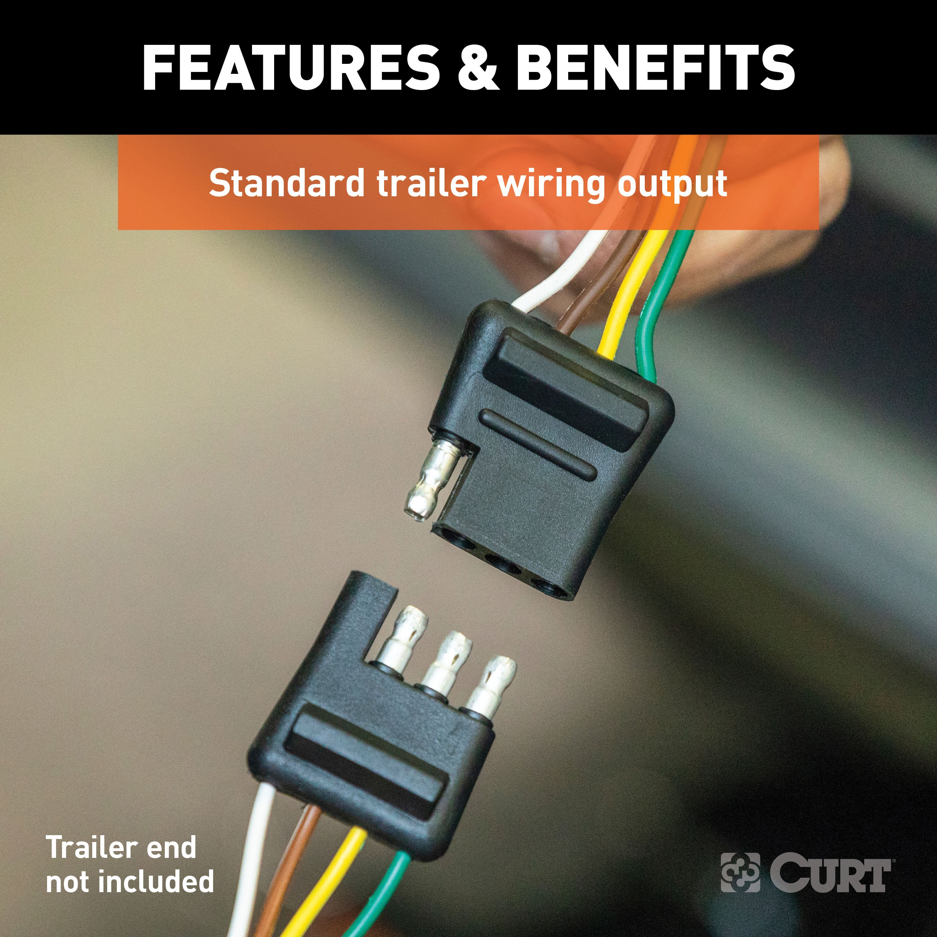
Output Type: 4-Way Flat
Tail Light Circuits: 5.0 Amps
Turn and Brake Circuits: 7.5 Amps
Installation Time Exact (Minutes): 0
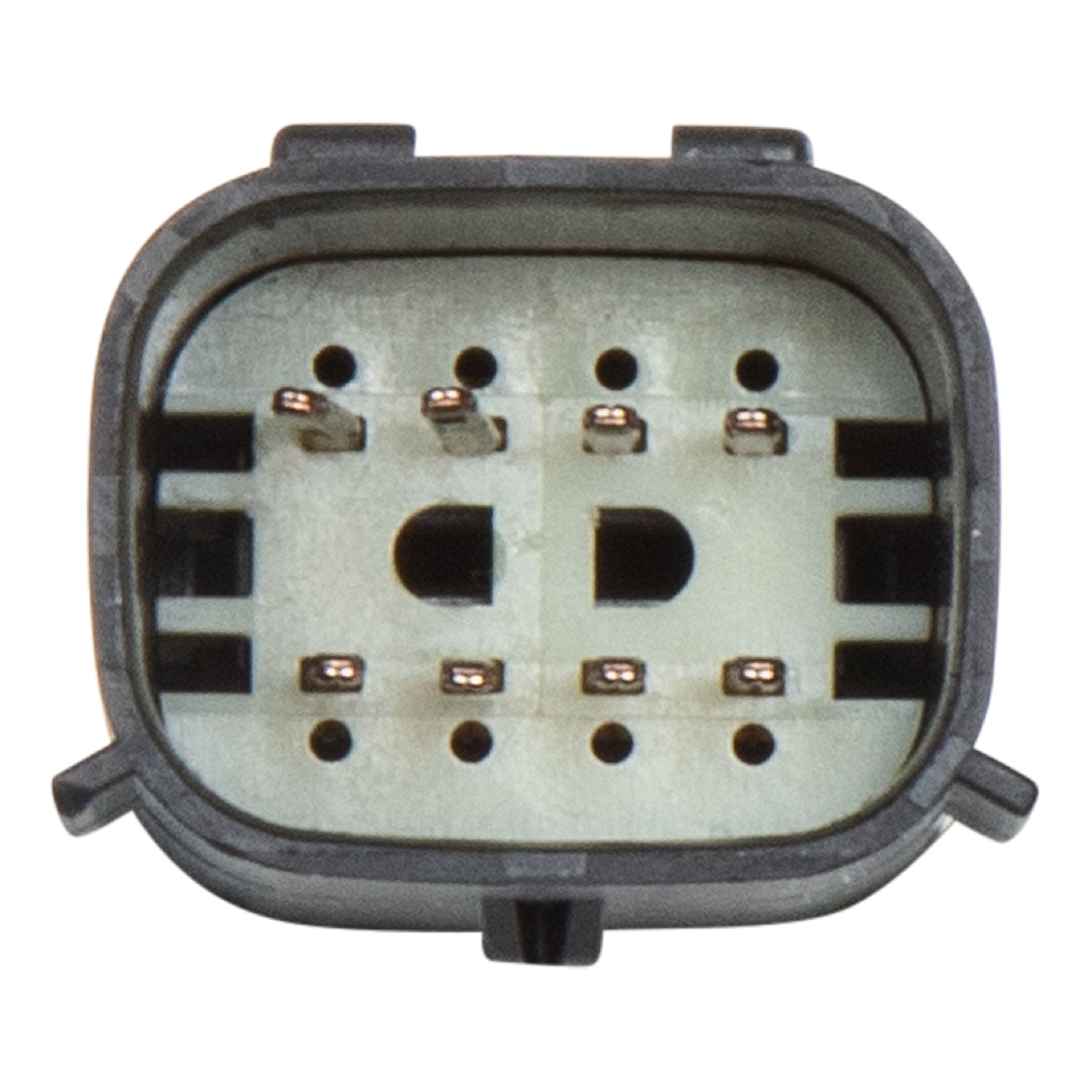
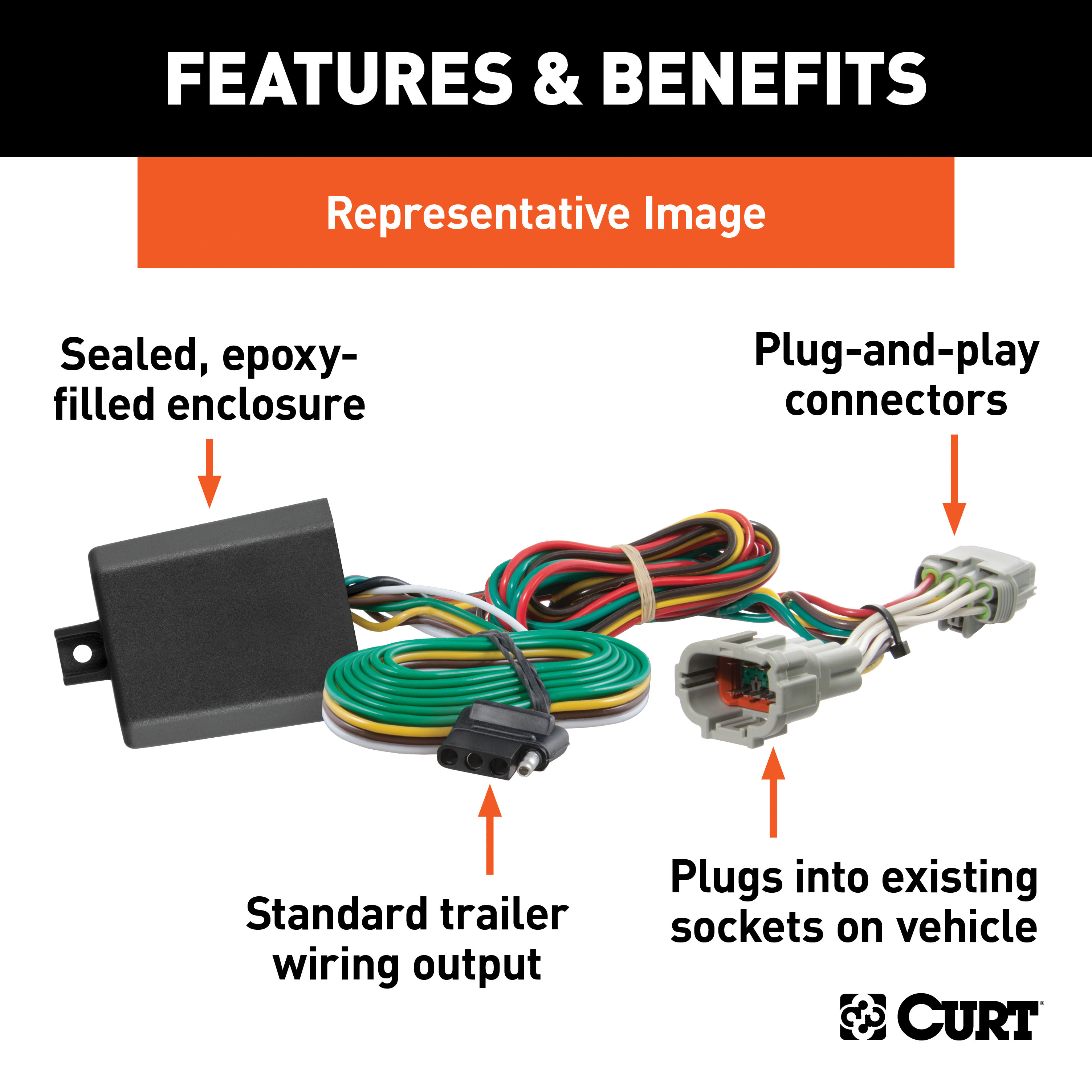
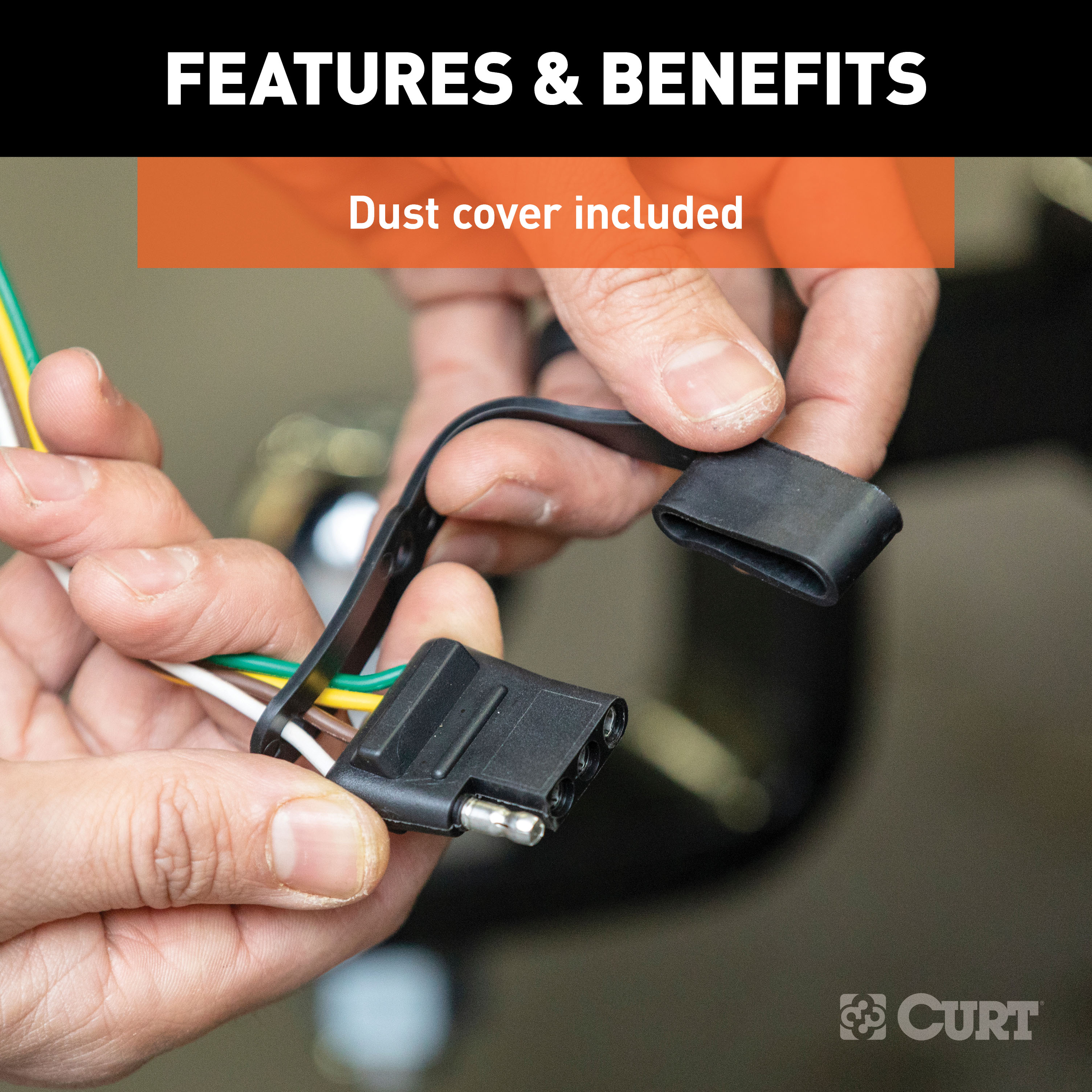
If your vehicle is not equipped with wiring for towing a trailer, CURT custom wiring is the ideal solution. A custom wiring harness -- also called a T-connector -- is a simple, plug-and-play electrical device that plugs into your automotive electric system and provides a standard, universal trailer wiring connection. This is done using two or more vehicle-specific, OEM-compatible connectors to plug into the taillight assembly, eliminating the need for cutting, splicing and soldering during installation. Custom wiring harnesses are made vehicle-specific, and while they are not available for all vehicles, they do offer one of the fastest, easiest and most secure ways to wire a vehicle for towing. This particular plug-in harness provides a 4-way flat connector socket and is designed to be a custom wiring harness to fit certain years of the Chevrolet Trax (to verify your vehicle compatibility, see application info). It comes with all necessary wiring components to establish a reliable trailer wiring connection, as well as a dust cover to keep the connector clean when not in use. You have a picture in mind of your next destination -- maybe it's the boat landing at your favorite fishing spot, maybe it's a campsite that overlooks one of nature's masterpieces, or maybe it's the next big jobsite. However, turning that picture into a reality takes more than just daydreaming. It takes a solid connection and the right amount of power. CURT custom wiring is made with some of the most sophisticated technology in the industry and is designed to install with ease, giving you a long-lasting electrical connection for your towing hitch setup.

CURT offers a variety of high-quality trailer hitches and accessories for select vehicle models. Find the perfect fit for your towing needs at TowUniverse.
CURT, a Lippert brand, offers a complete line of towing products and is the leading manufacturer of custom-fit trailer hitches. We offer the broadest selection of custom-fit hitches, and each one is designed, welded, and coated in Wisconsin.
CURT is also a leader in flat towing products, as well as 5th wheel, gooseneck, and weight distribution hitches, ball mounts, electrical components, cargo solutions, and other towing accessories.
For everything from passenger cars and vans to full-size pickups and SUVs, CURT is 'The First Name in Towing Products®.'

Experts available to answer your questions
Call 888-634-9494One-Year
1 compatible vehicles
| Year | Make & Model | Notes |
|---|---|---|
| 2024 - 2026 | Chevrolet Trax | Installation Time: 30-60 minutes |
The CURT 56514 is specifically designed to fit 2024-2025 Chevrolet Trax models. This custom wiring harness uses vehicle-specific, OEM-compatible connectors that plug directly into the taillight assembly of these particular years. Always double-check your exact year, make, and model before ordering to ensure proper fitment.
Yes, the CURT 56514 is designed to fit 2024-2025 Chevrolet Trax models, so your 2025 Trax is covered. It provides a 4-way flat output that connects your tail lights, brake lights, and turn signals with circuits rated at 5.0 amps for tail lights and 7.5 amps for turn and brake functions.
Absolutely! The CURT 56514 fits 2024-2025 Chevrolet Trax models perfectly. It comes with a tail light converter for vehicle-trailer compatibility and includes SMT circuitry for enhanced performance and durability, plus a dust cover to keep the 4-way flat connector clean when not in use.
Installation of the CURT 56514 is actually very straightforward thanks to its simple plug-and-play design. It plugs directly into your vehicle's tail light assembly without any cutting or splicing required, and basic hand tools are typically all you need. Most people can complete the installation in 30-60 minutes, plus you'll need to make a vehicle battery connection as part of the setup.
The Curt 56514 is a custom wiring harness with a powered converter designed for passenger cars with 12-volt negative ground electrical systems. It converts vehicle taillight signals to trailer lighting signals and includes a converter box that mounts inside the trunk. The system handles signal circuits (7.5 amps per side) and tail/running circuits (5.0 amps total).
The Curt 56514 is designed for passenger cars with 12-volt negative ground electrical systems. Check your vehicle owner's manual to confirm your vehicle has a 12-volt negative ground system and to locate the battery. The manual does not specify which vehicle models or years are compatible, so contact Curt Manufacturing or your dealer for fitment confirmation.
Yes. The installation involves locating your vehicle's taillight wiring connectors (behind the taillight housing inside the trunk on both driver and passenger sides) and inserting the custom harness T-end with the yellow wire between the separated connectors. The connectors have external red locks and internal locks that must be released carefully during disconnection.
You will need: ratchet, wire cutter, 10mm socket, wire crimp tool, and panel trim removal tool. These are listed as required tools on page 1 of the manual.
The manual shows a Hardware Photo but does not itemize the included components. Based on the installation steps, the kit includes: a black converter box, a T-end connector with yellow wire, white ground wire with ring terminal, green wire, black power wire, ground screw, double-sided tape, cable ties, 4-flat dust cover, and a 15-amp fuse holder. Contact Curt Manufacturing for a complete parts list.
Yes. Step 1 requires you to disconnect the negative battery terminal before beginning installation. Fasten this wire down and away from the battery during the installation process. Reconnect the negative battery terminal only after all other steps are complete and before testing the system.
Yes. Step 2 requires you to remove the floor board to expose the spare tire. Use a trim tool to loosen the threshold and remove it straight up. The manual does not specify whether the spare tire itself must be removed or whether the floor board is reinstalled after installation.
The manual rates the installation difficulty as 'Easy'. However, the actual time and effort may vary depending on your experience level, your vehicle's condition, and whether you have the proper tools and equipment.
The black converter box mounts on a flat spot on the bottom of the trunk between the driver-side wall panel using the provided double-sided tape (Step 6). The area must be clean and flat for proper adhesion.
Locate the taillight wiring connectors behind the taillight housing (accessed after loosening the sidewall with a trim tool). The connectors have an external red lock that must be released by moving the tab towards the housing wire, and an internal lock that must be pressed in to unlock. The housings release easier if you push them together, press the lock release until it clicks, then pull the housings apart. Take care not to damage the locking tabs.
The green wire routes from the driver side to the passenger side along the back of the vehicle. Secure it in place using the provided cable ties (Step 8). This routing is done after repeating the taillight connector installation steps on the passenger side.
When in use, route the 4-flat with the center of the vehicle and out of the hatch to the trailer, staying clear of the hatch's latching mechanism. When not in use, roll it up and store in a convenient, out-of-the-way location. Install the provided 4-flat dust cover to help prevent corrosion.
Drilling may be required for the ground wire connection. Step 7 instructs you to locate an existing screw or bolt in the vehicle frame as a grounding point, or drill a 3/32-inch pilot hole if no existing fastener is available. The area must be free from rust, dirt, and paint (use an abrasive pad or paper to clean it). Always check for hidden items behind or under any surface before drilling to avoid damage and personal injury.
If an existing fastener is not available, drill a 3/32-inch pilot hole for the ground wire connection. The area should be free from rust, dirt, and paint before drilling.
No permanent modifications are required. The installation involves removing and reinstalling interior trim panels (floor board, threshold, sidewall) using a trim tool. All removed items must be reinstalled after the wiring is complete.
Signal circuits are rated at 7.5 amps per side. Tail and running circuits are rated at 5.0 amps total. Do not exceed the product rating or the tow vehicle lamp load rating, whichever is lower.
The battery connection must be fuse-protected with a 15-amp maximum fuse. Exceeding this rating can cause loss of warranty, overheating, and potential fire. The fuse must be installed after all other installation steps are complete.
The power wire is 12 GA (12 gauge) or larger. It must be routed from the vehicle battery to the converter, taking care to avoid pinch points and hot or rotating components. When passing through sheet metal, use an existing grommet, add a grommet, or use silicone to protect the wire from sharp edges.
The wiring harness includes: green wire (right turn), red wire (brake), yellow wire (left turn), and brown wire (taillight). The white ground wire connects to the vehicle frame. The black power wire connects to the positive battery terminal. The yellow wire T-end installs between the vehicle's taillight connectors.
The white ground wire has a ring terminal that must be attached to the vehicle body using either an existing screw or bolt in the frame, or a provided ground screw in a 3/32-inch drilled hole. The mounting area must be free from rust, dirt, and paint. Use an abrasive pad or paper to clean the area before securing the ring terminal.
Route the 12 GA black power wire from the vehicle battery to the converter using the provided 'Powered Converter Lead Instruction Sheet' on page 5 of the manual. The black wire connects to the positive (+) battery terminal using a ring terminal. The battery connection must be fuse-protected with a 15-amp maximum fuse, installed after all other steps are complete. Secure the power wire to the vehicle chassis using the provided cable ties, and protect it from sharp edges when passing through sheet metal using an existing grommet, adding a grommet, or using silicone.
The installation uses wiring locations P3 and P4: P3 is behind the driver side taillight housing inside the trunk, and P4 is behind the passenger side taillight housing inside the trunk. These locations are where the vehicle's taillight wiring connectors are accessed to install the custom harness.
Do not lay tools across the positive battery terminal (typically marked with red covers or a red '+' symbol), as this can cause a ground short resulting in sparks and electrical shocks. Disconnect the negative battery terminal before beginning installation and fasten it down and away from the battery. Check for hidden items behind or under any surface before drilling to avoid damage and personal injury. Route the 12 GA power wire avoiding pinch points and hot or rotating components. Use a ring terminal for the battery connection. If using the converter as a powered module for a two-wire system, the red brake wire must be grounded.
The manual does not specify a maximum tow load or capacity rating. It states: 'Do not exceed product rating or tow vehicle lamp load rating, whichever is lower.' Check your vehicle owner's manual or contact the vehicle manufacturer for the tow vehicle lamp load rating.
After connecting the 12-volt power wire to the harness, verify that the harness is functioning by attaching the battery and testing with a test light, 4-flat tester, or a functioning trailer. The manual recommends testing before fully completing the installation to ensure proper function.
After installation, reinstall all items removed during the installation process (floor board, threshold, sidewall, cargo tie-downs). Reconnect the negative battery terminal if it was disconnected. Secure any loose wires with the provided cable ties. Install the provided 4-flat dust cover to help prevent corrosion. Test the system with a test light, 4-flat tester, or functioning trailer to confirm proper operation.
Periodic inspection of all wires and connections should be performed to ensure there is no visible damage or loose connections. The manual does not specify an inspection interval. Check your vehicle owner's manual or contact Curt Manufacturing for recommended maintenance intervals.
The Curt 56514 is designed for passenger cars with 12-volt negative ground electrical systems. Confirm your vehicle's electrical system type in your owner's manual. Contact Curt Manufacturing for specific vehicle model compatibility.
First, verify that the 15-amp fuse is installed in the fuse holder after all other installation steps are complete. Confirm that the negative battery terminal is reconnected. Test the system with a test light, 4-flat tester, or functioning trailer. Check that all wire connections are secure and that the taillight connectors are properly seated with the yellow wire T-end installed between them. Inspect all wires for visible damage or loose connections. Ensure the white ground wire ring terminal is securely attached to a clean, rust-free mounting point on the vehicle frame.
The connectors have an external red lock and an internal lock. Release the external red lock by moving the tab towards the housing wire. Press the internal lock to unlock the housings. The housings release easier if you push them together first, then press the lock release until it clicks, and finally pull the housings apart. Take care not to damage the locking tabs during this process.
On Sale Today
Original price was $141.95. Current price is $113.99.You save $27.96 (20%)
Free Shipping
Ships free on all orders
 Authorized Dealer

Quick Ship
In stock and ready to ship — order now!
Shipping from Eau Claire, WIFREE SHIPPING
Estimated delivery Tue, Sep 29 - Thu, Oct 1
Order before 2 PM EST Monday–Friday for same-day processing
Guaranteed safe & secure checkout
Total for 4 items:
$189.94$217.90
No reviews have been added for this product.