
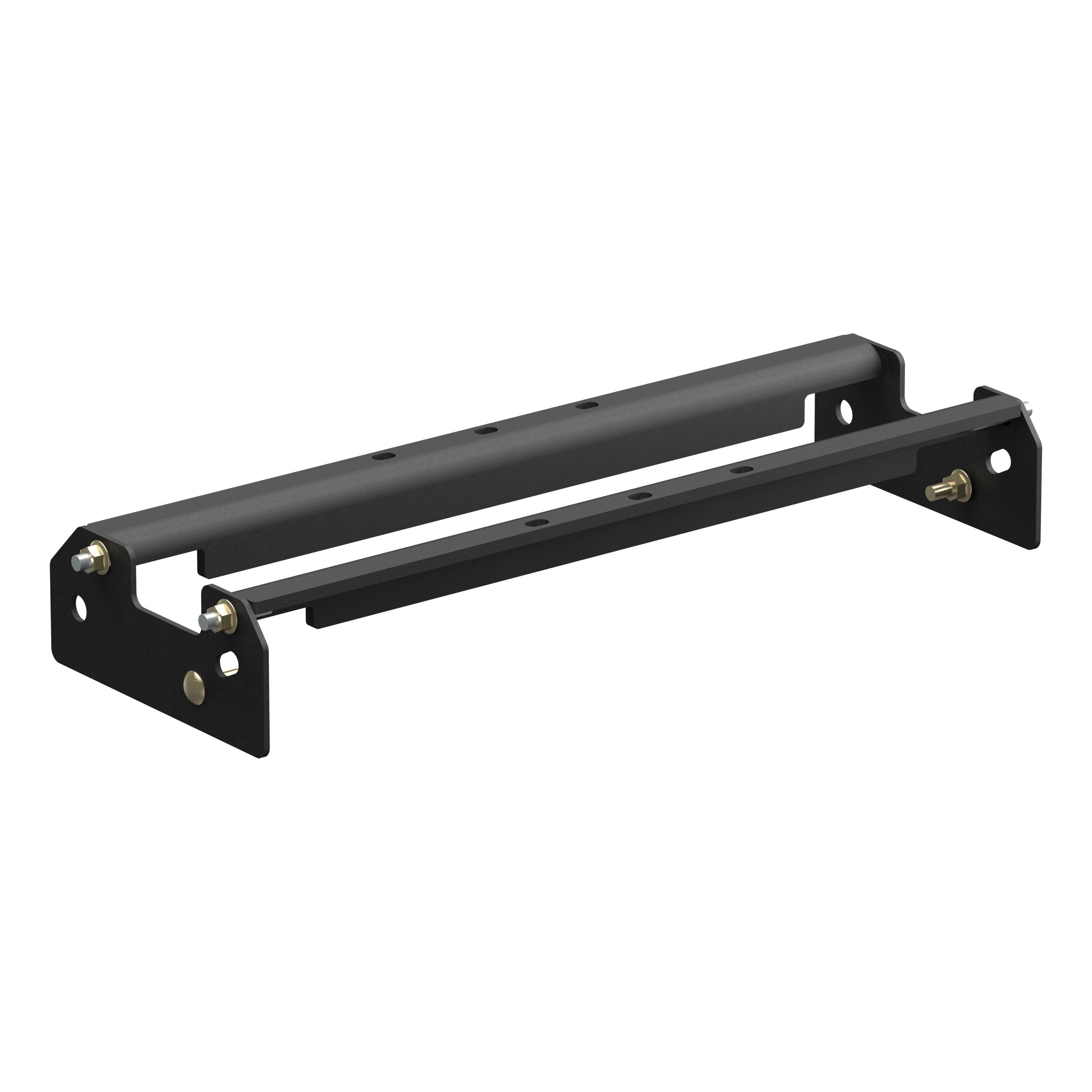
CURT Under-Bed Gooseneck Installation Brackets, Select Ford F-250, F-350, F-450 Gooseneck Trailer Hitch Mount KitCURTOriginal price was $444.95. Current price is $275.99.In Stock
View productOur in-house experts typically reply within one business day.

CURT


Always the correct part
We know our products
Quality Products
Free Shipping!
Always the correct part
We know our products
Quality Products
Free Shipping!
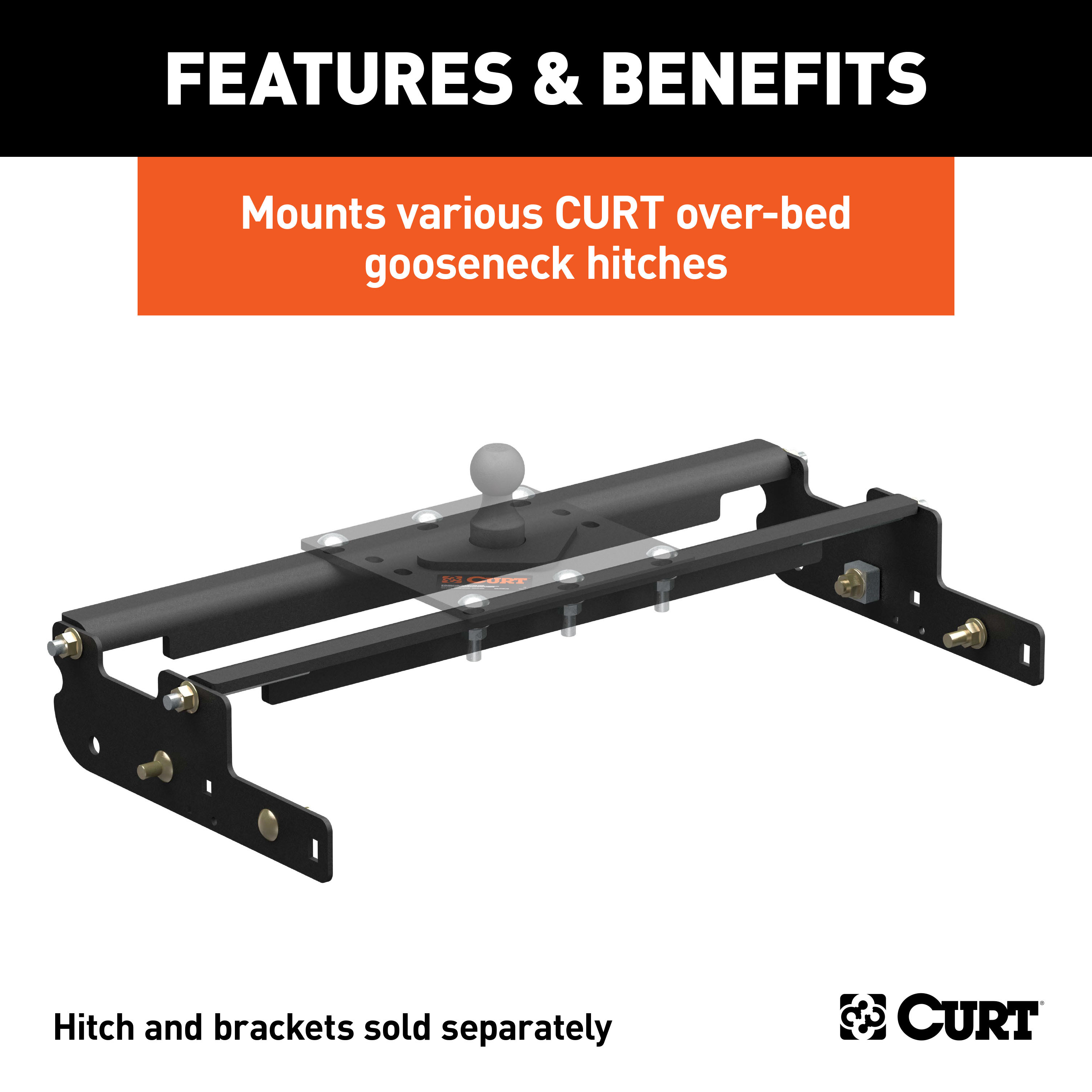
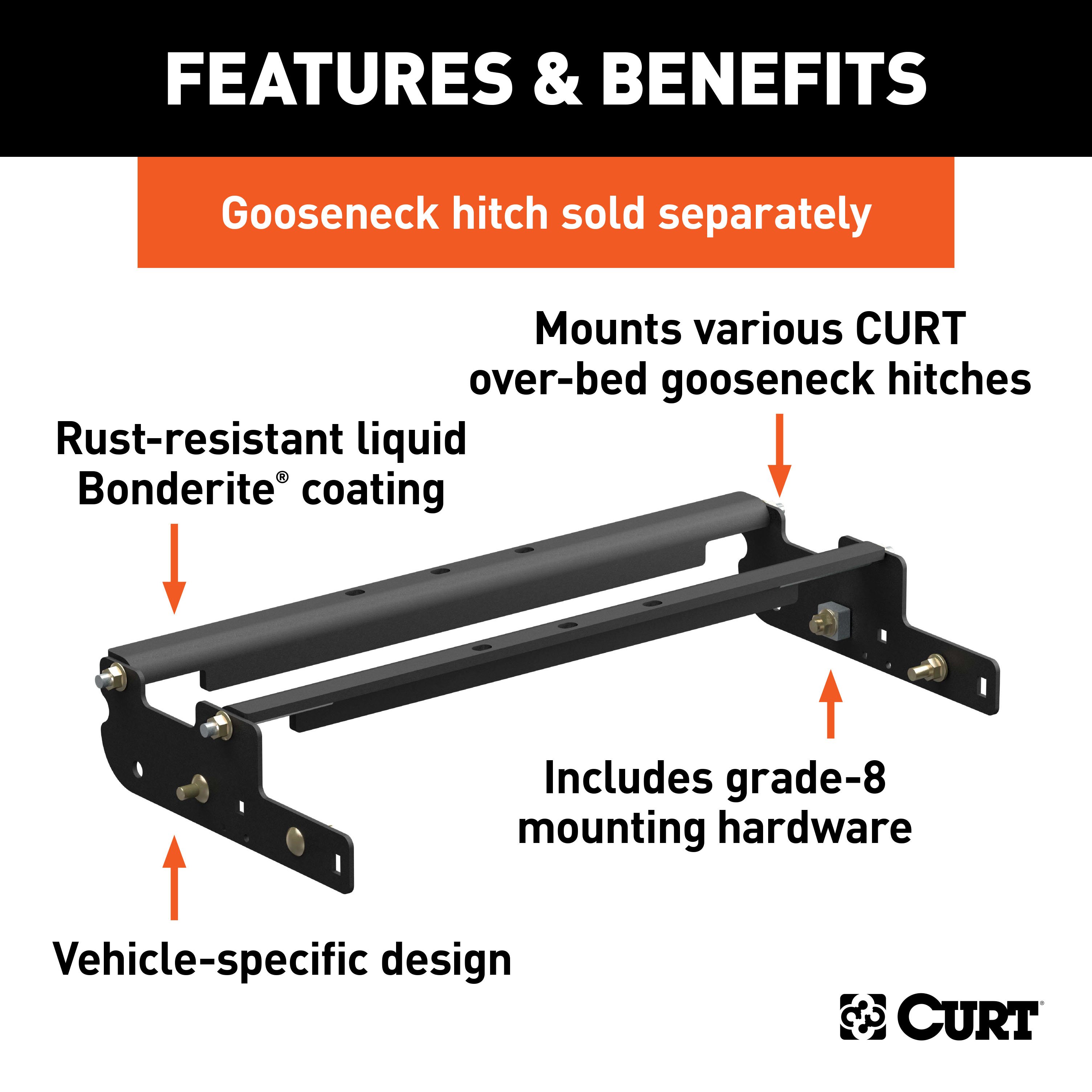
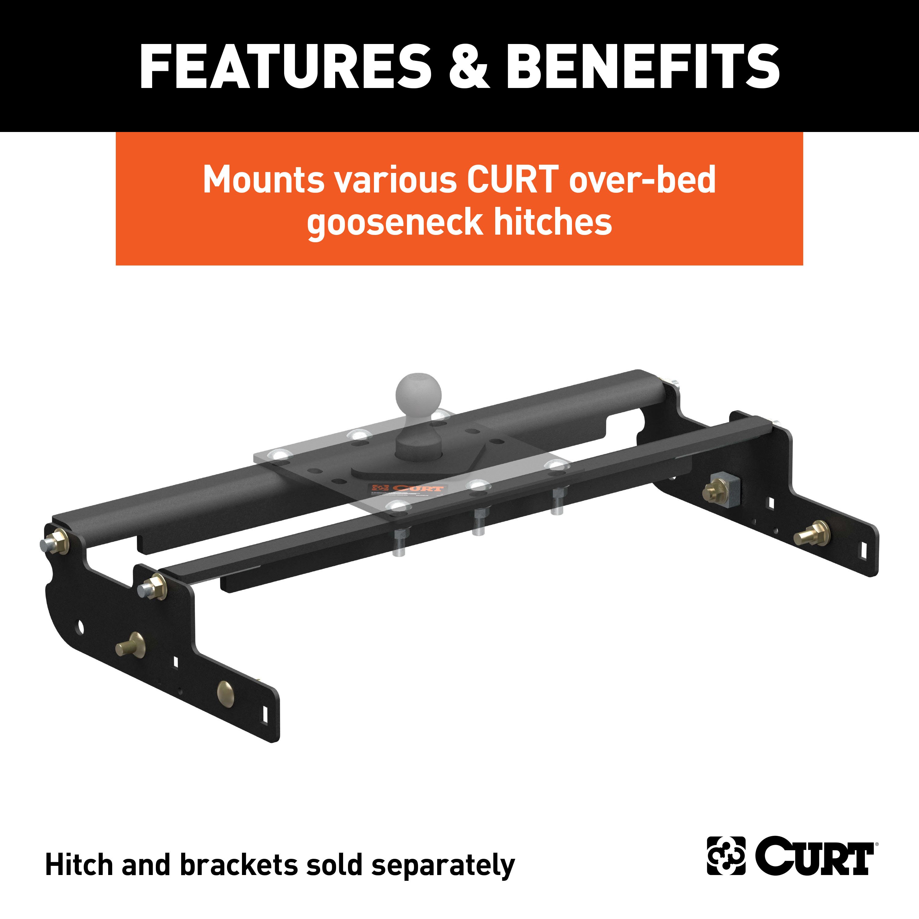
Includes mounting brackets only (gooseneck hitch sold separately)
Capacity limited to lowest-rated towing component

Includes mounting brackets only (gooseneck hitch sold separately)
Warranty: Limited Lifetime Warranty (One-Year Finish, One-Year Parts)
Color: Black
Finish: A-COAT
Installation Time Exact (Minutes): 0
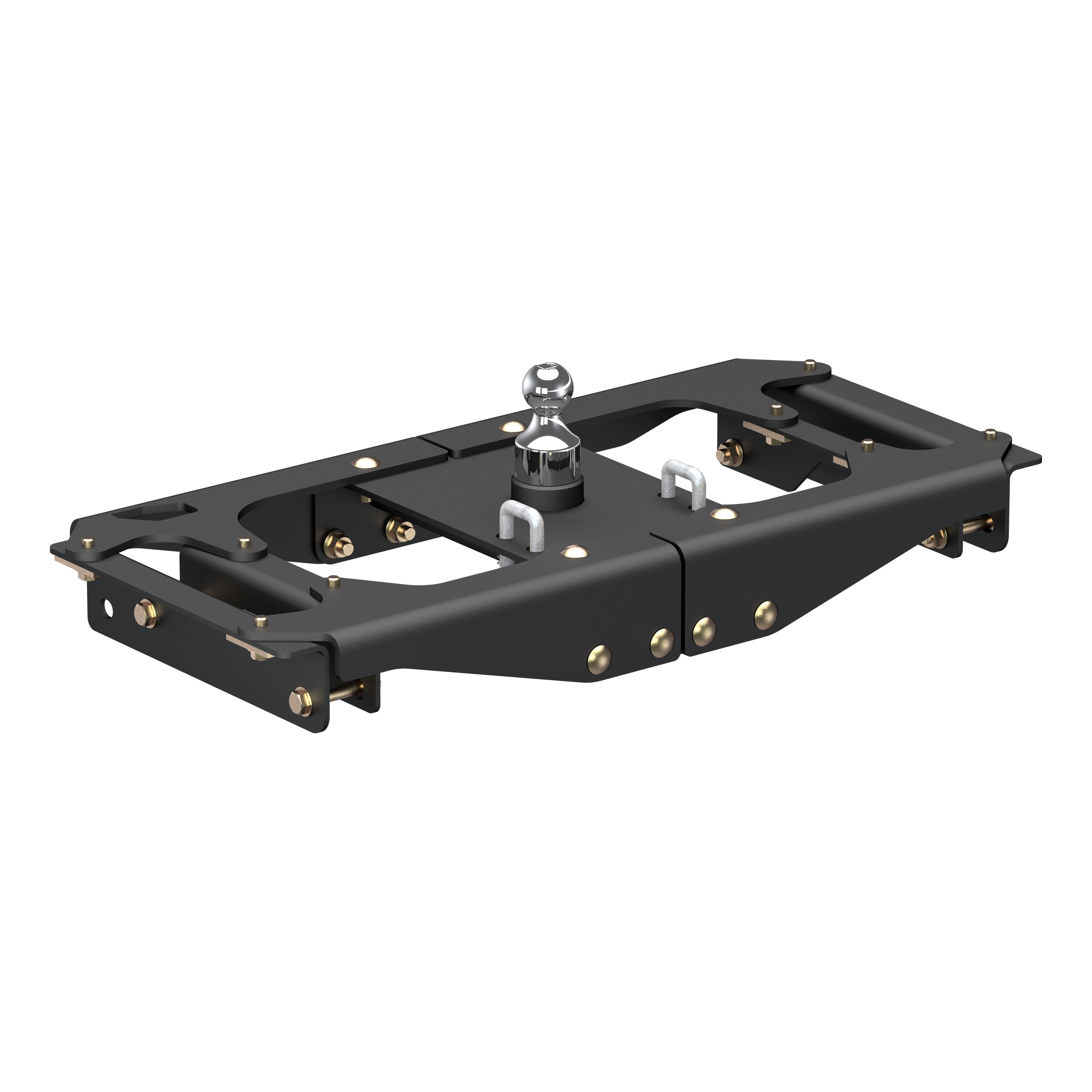
Choosing the right gooseneck hitch is only half the battle in preparing your pickup truck for towing a gooseneck trailer. CURT gooseneck hitches are a premium option in the heavy-duty towing industry, but they are only one of the members in the heavyweight tag team that is CURT gooseneck towing. While a gooseneck hitch gets all the glory above the floor of your truck bed, gooseneck installation brackets provide sure footing and a solid foundation for that oversized gooseneck trailer. Gooseneck installation brackets work by bolting onto the frame of your truck, typically using pre-existing holes. With a set of brackets firmly bolted on, a gooseneck hitch is able to be attached and is given the strength it needs to manage the massive amount of weight of a gooseneck trailer. With so many gooseneck hitch options available from CURT, we wanted to make sure we offered the gooseneck installation products needed to give you a complete towing package. Our installation brackets fit multiple vehicles and hitch heads. This particular set of over-bed gooseneck installation brackets is designed to fit multiple CURT gooseneck hitches and provide a custom fit on certain years of the Ford F250, F350 Super Duty or F450 Super Duty (excluding cab and chassis) (see application info to verify fitment). It has a maximum weight capacity of 30,000 lbs., includes grade-8 mounting hardware for a complete installation and features laser-cut construction for a precise fit.

CURT offers a variety of high-quality trailer hitches and accessories for select vehicle models. Find the perfect fit for your towing needs at TowUniverse.
CURT, a Lippert brand, offers a complete line of towing products and is the leading manufacturer of custom-fit trailer hitches. We offer the broadest selection of custom-fit hitches, and each one is designed, welded, and coated in Wisconsin.
CURT is also a leader in flat towing products, as well as 5th wheel, gooseneck, and weight distribution hitches, ball mounts, electrical components, cargo solutions, and other towing accessories.
For everything from passenger cars and vans to full-size pickups and SUVs, CURT is 'The First Name in Towing Products®.'

Experts available to answer your questions
Call 888-634-9494Rediscover "Us" Time | Tested. Proven. Safe. Towing Products
Yes, the CURT Over-Bed Gooseneck Installation Brackets, Select Ford F-250, F-350, F-450 Gooseneck Trailer Hitch Mount Kit (Part #BKDK61332) is designed to fit the 1999-2015 Ford F-250 Super Duty.
The CURT Over-Bed Gooseneck Installation Brackets, Select Ford F-250, F-350, F-450 Gooseneck Trailer Hitch Mount Kit (Part #BKDK61332) fits the following vehicles: 1999-2015 Ford F-250 Super Duty; 1999-2015 Ford F-350 Super Duty; 2008-2011 Ford F-450 Super Duty. Always verify your specific year, make, and model before ordering.
The CURT Over-Bed Gooseneck Installation Brackets, Select Ford F-250, F-350, F-450 Gooseneck Trailer Hitch Mount Kit (Part #BKDK61332) fits 1999-2015 Ford F-250 Super Duty models. The 2015 model year is the last year covered by this part number. For newer models, check for an updated version.
The CURT Over-Bed Gooseneck Installation Brackets, Select Ford F-250, F-350, F-450 Gooseneck Trailer Hitch Mount Kit (Part #BKDK61332) Drilling is not required for installation. Typical installation time is . Basic hand tools are typically all you need.
The Curt 61332 fits 1999–current Ford 3/4 and 1 ton Super Duty trucks and the 2008 F-450. Installation steps vary by model year: 2005 models require exhaust hanger modification and spacer plate installation; 2008–current models require drilling an additional frame hole; and 2011 Ford Super Duty diesel models require different hardware orientation on the driver side. Confirm your truck's year and engine type before purchasing.
Yes, the 61332 fits 2011 Ford Super Duty diesel models, but hardware orientation is different on the driver side. Figure 2 in the manual shows the correct orientation for this configuration. Ensure you follow the driver-side diesel-specific hardware placement during installation.
Yes, the 61332 is compatible with the 2008 F-450. The 2008 model requires drilling an additional frame hole to fit the 5/8" bolt on current-model trucks, as noted in Step 7. Exhaust work for the 2008 model uses Exhaust Strap 2 (CM-ES2) instead of the spacer plate used on 2005 models.
The kit is rated for a 30,000 lbs gross towing weight (GTW).
Yes. The manual explicitly states: **REMOVE SPARE TIRE FOR INSTALLATION**. This is required before beginning any installation steps.
Yes. The manual states that all models require modification or removal of heat shields. Step 1 specifies removing the heat shield located above the rear axle if equipped. The gas tank heat shield may also need to be cut along the top for some models. These modifications are permanent.
Possibly. The manual warns that brake, fuel, and electrical lines may need to be loosened or repositioned. For 2005 models, the exhaust hanger mount must be loosened, a spacer plate inserted, and the exhaust lowered approximately 1/2". The rear exhaust hanger is removed and replaced with Exhaust Strap 1. For 2008 models, Exhaust Strap 2 is used. The exhaust may need to be lowered further for cross arm clearance. Have a qualified technician assess your specific truck.
Possibly. The manual warns that brake, fuel, and electrical lines may need to be loosened or repositioned to provide clearance for new hardware. Step 10 specifically instructs to check for brake and fuel lines before drilling. Step 15 requires reattaching any brake, fuel, or electrical wires so they have adequate clearance to added fasteners. Have a qualified technician assess your truck before installation.
Required tools include: 9/16" socket, 5/8" wrench, 15/16" wrench, 1/8" drill bit, 21/32" drill bit, sabre saw, and a torque wrench capable of 210 ft-lbs. A cutting template (provided) is used to mark drilling locations. Additional tools may be needed for exhaust work and brake/fuel line repositioning depending on your truck's configuration.
The manual references the C-52 folding hitch ball in Steps 12–13 but does not list it in the parts list. Contact Curt Manufacturing or your supplier to confirm whether the C-52 is included or must be purchased separately.
Cross arms must be placed in the correct orientation as shown in Figure 2. The cross arms are slid into the gap between the truck bed and frame on the passenger side, then swung between the truck bed and frame gap on the driver side. The rear cross arm studs must be centered in the side plate slots (Figure 3) before final tightening.
Fasteners are tightened in stages. Steps 6–7 require finger-tight fastening only. Step 9 requires tightening the rear cross arm flange nuts to the side plates using a 15/16" wrench, then tightening the front cross arm flange nuts after cross arms are evenly spaced. Step 14 specifies final torque values: 5/8" flange nuts on cross arms to side plates: 210 ft-lbs; 5/8" bolts and nuts securing side plates to frame: 210 ft-lbs; 3/8" hardware: 45 ft-lbs; 5/16" hardware: 23 ft-lbs.
The spacer tube (CM-TS, .706 DIA) is used to evenly space the cross arms during Step 9. U-shaped spacers (CM-SP27, .188 x 1.00 x 2.00", qty 12) must be placed under each of the six bolts between the cross arms and folding hitch ball to prevent the bed floor from collapsing. This is a critical safety requirement.
Yes. Drilling is required. Step 10 requires drilling six 1/8" pilot holes through the cross members up through the pickup bed, then four additional 1/8" pilot holes through section "B" of the cutting template. Step 12 requires drilling out all six holes to 21/32" diameter to fit the C-52 folding hitch ball. A sabre saw is used in Step 11 to cut out section "C" of the template. For 2008–current models, an additional frame hole must be drilled to fit the 5/8" bolt (Step 7).
Drill 1/8" pilot holes through the center of each of the six holes in the cross members up through the pickup bed. From inside the bed, center these six pilot holes with the letter "A" on the cutting template and fasten the template with tape. Then drill four additional 1/8" pilot holes through section "B". Holes must be drilled in the lower rib sections of the truck bed (Figure 4), not the high rib sections. Check for brake and fuel lines before drilling.
The gas tank heat shield may need to be cut along the top for some models. The manual does not specify which models require this modification. Inspect your truck's heat shield during Step 1 and cut as needed to provide clearance for the kit.
Final torque specifications are: 5/8" flange nuts on cross arms to side plates: 210 ft-lbs; 5/8" bolts and nuts securing side plates to frame: 210 ft-lbs; 5/8" carriage bolts attaching the C-52 folding hitch ball to cross arms: 210 ft-lbs; 3/8" hardware (emergency brake cable support): 45 ft-lbs; 5/16" hardware: 23 ft-lbs. All torque specifications are applied in Step 14 after the C-52 has been fastened.
5/8" carriage bolts and flange nuts are torqued to 210 ft-lbs. This applies to: (1) the six bolts attaching the C-52 folding hitch ball to the cross arms (Step 13), and (2) the bolts and nuts securing the side plates to the frame (Step 14).
3/8" hardware (used for the emergency brake cable support) is torqued to 45 ft-lbs.
5/16" hardware is torqued to 23 ft-lbs.
Step 2 requires removing the emergency brake cable support from the driver side frame using a 9/16" socket. Step 8 requires reinstalling it using 3/8" hex bolts, washers, and flange nuts. Step 14 specifies torquing the 3/8" hardware to 45 ft-lbs.
For 2005 models: (1) Loosen the two bolts on the exhaust hanger mount in front of the rear axle between the exhaust hanger and truck bed. (2) Lower the exhaust approximately 1/2" and insert the 1/2" spacer plate provided. (3) Retighten the bolts. (4) Remove the rear exhaust hanger and install Exhaust Strap 1. (5) Lower the exhaust as needed for cross arm clearance. These steps are required before installing the cross arms.
For 2008 models with a two-bolt exhaust mount: Remove the factory mount from the frame and place it on the bracket. Place a carriage bolt through the top square hole in the bracket and attach to the frame. Secure with a flange nut. Re-attach the factory mount using the bolts removed earlier in the two holes. Exhaust Strap 2 (CM-ES2) is used for 2008 models.
1/4" spacers (CM-SP15, .250 x 1.50 x 1.50", qty 6) are used as needed to fill the gap between the frame and side plate when installing the 5/8" carriage bolts through the side plates and frame (Step 7). Use as many spacers as necessary to ensure proper fit.
After rotating the cross arms until they contact the truck bed, center the rear cross arm studs in the side plate slots. According to Figure 3, the cross arm stud is centered when the flange nut covers the slot. Use a 15/16" wrench to tighten the 5/8" flange nuts on the rear cross arm to the side plates.
After installation, reattach any brake, fuel, or electrical wires so they have adequate clearance to added fasteners (Step 15). Verify that all fasteners are torqued to specification: 5/8" flange nuts and bolts to 210 ft-lbs, 3/8" hardware to 45 ft-lbs, and 5/16" hardware to 23 ft-lbs. Confirm that U-shaped spacers are in place under each bolt between the cross arms and folding hitch ball.
U-shaped spacers must be placed under each of the six bolts between the cross arms and folding hitch ball to prevent the bed floor from collapsing. This is a critical safety requirement. The manual explicitly states this in Step 13.
The kit includes: 2× 5/16" carriage bolts, 2× 5/16" flange nuts, 2× 3/8" hex cap screws, 2× 3/8" flat washers, 2× 3/8" serrated flange nuts, 4× 5/8" carriage bolts, 1× 5/8" hex cap screw, 8× 5/8" serrated flange nuts, 6× 1/4" spacers, 12× U-shaped spacers, 2× 5/8" flat washers, 1× Exhaust Strap 1, 1× Exhaust Strap 2, 1× exhaust spacer plate, 1× tube spacer, and 1× 1/4" spacer. The C-52 folding hitch ball is referenced but not listed in the parts list; confirm with your supplier whether it is included.
The 61332 fits 1999–current Ford 3/4 and 1 ton Super Duty and the 2008 F-450. Installation steps vary by model year and engine type (2011 diesel models have different hardware orientation). Confirm your truck's year and engine before purchasing.
You need: 9/16" socket, 5/8" and 15/16" wrenches, 1/8" and 21/32" drill bits, sabre saw, torque wrench (to 210 ft-lbs), and the provided cutting template. Additional tools may be needed for exhaust and brake/fuel line work depending on your truck.
Yes, the spare tire must be removed before installation begins.
5/8" bolts and flange nuts: 210 ft-lbs (cross arms to side plates, side plates to frame, and C-52 hitch ball). 3/8" hardware: 45 ft-lbs. 5/16" hardware: 23 ft-lbs.
Yes. U-shaped spacers must be placed under each of the six bolts between the cross arms and folding hitch ball to prevent bed floor collapse. This is a critical safety requirement.
Yes. All models require modification or removal of heat shields. The heat shield above the rear axle must be removed, and the gas tank heat shield may need to be cut along the top for some models.
Do not tighten the front cross arm until the cross arms are evenly spaced. Use the spacer tube provided to evenly space the cross arms first (Step 9). Once evenly spaced, tighten the front cross arm flange nuts using a 15/16" wrench.
Ensure the side plate is aligned with the 3/4" slot in the frame before inserting the 5/8" carriage bolts. Use 1/4" spacers as needed to fill any gaps between the frame and side plate (Step 7). Adjust the number of spacers until proper alignment is achieved, then secure with flange nuts finger-tight before final torquing.
Stop drilling immediately. The manual requires checking for brake and fuel lines before drilling (Step 10). If a line is damaged, do not proceed with installation. Consult a qualified technician or Ford dealer to assess and repair the damage before continuing.
U-shaped spacers were not placed under the bolts between the cross arms and folding hitch ball. These spacers are required to prevent bed floor collapse (Step 13). Remove the bolts, install U-shaped spacers under each of the six bolts, and retighten to 210 ft-lbs.
On Sale Today
Original price was $444.95. Current price is $275.99.You save $168.96 (38%)
Free Shipping
Ships free on all orders
 Authorized Dealer


Quick Ship
In stock and ready to ship — order now!
Shipping from Eau Claire, WIFREE SHIPPING
Estimated delivery Sun, Oct 25 - Tue, Oct 27
Order before 2 PM EST Monday–Friday for same-day processing
Guaranteed safe & secure checkout
No reviews have been added for this product.