CURT 8-10K TruTrack 4P Weight Distribution Hitch with 4x Sway ControlCURTOriginal price was $906.95. Current price is $609.95.In Stock
View productOur in-house experts typically reply within one business day.

CURT




Always the correct part
We know our products
Quality Products
Free Shipping!
Always the correct part
We know our products
Quality Products
Free Shipping!
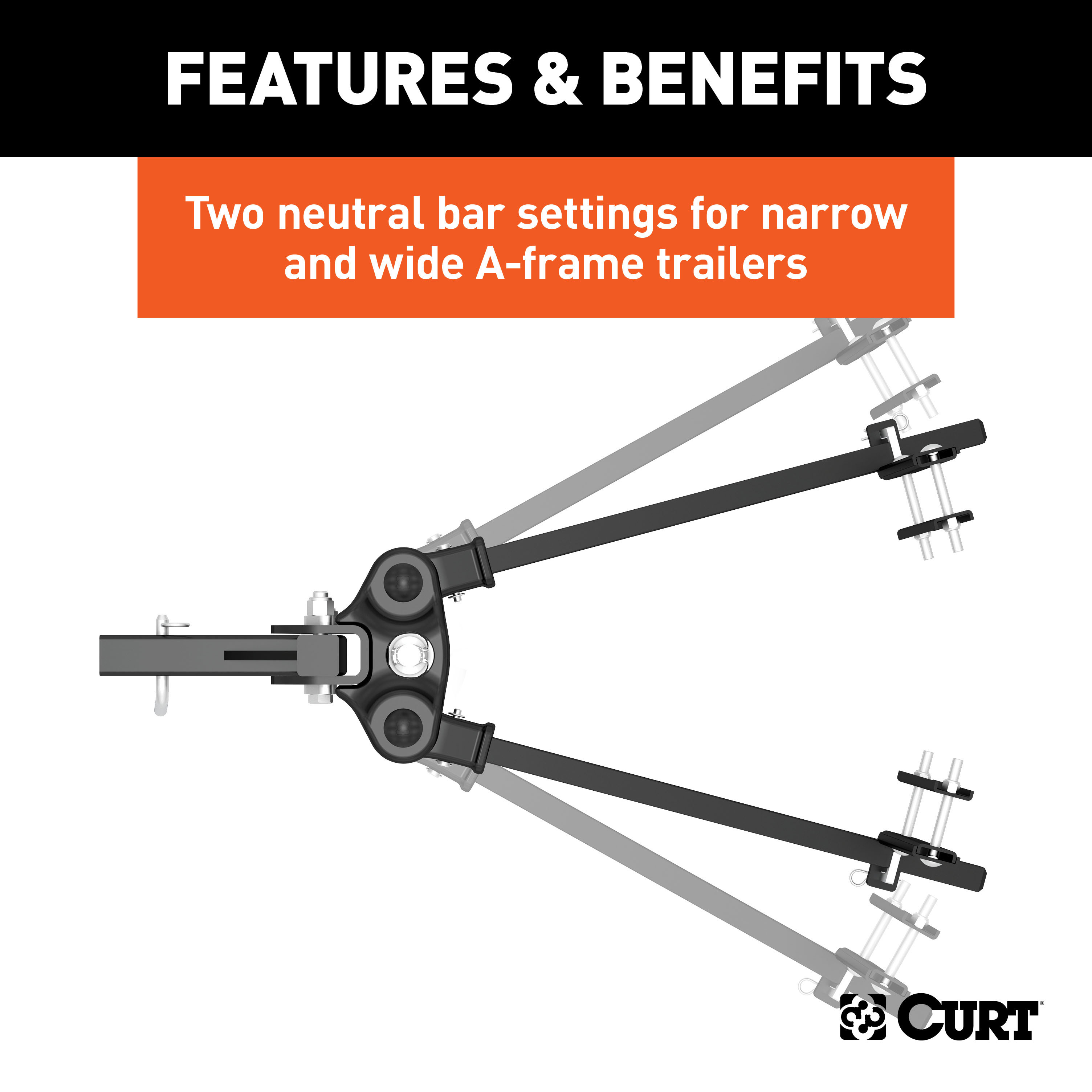
Springs bars can be adjusted to 30 or 70 degrees (+/- 5)
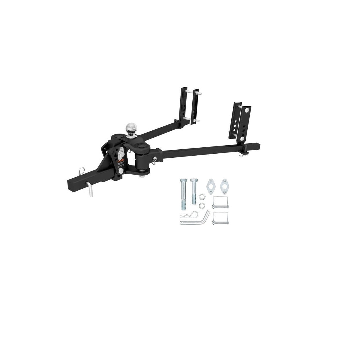
Includes shank, trailer ball, spring bars, head, support brackets, pin & clip
Capacity limited to lowest rated towing component (Lowest hole in shank cannot be used in drop position)

Includes shank, trailer ball, spring bars, head, support brackets, pin & clip

Warranty: Limited Lifetime Warranty (One-Year Finish, One-Year Parts)
Finish: CARBIDE BLACK POWDER COAT
WC / TW (Pounds): 1,000 LB - 1,500 LB
WC Tongue Weight (Pounds): 1,000 LB - 1,500 LB
Gross Trailer Weight (Pounds): 10,000 LB - 15,000 LB
Installation Time Exact (Minutes): 0
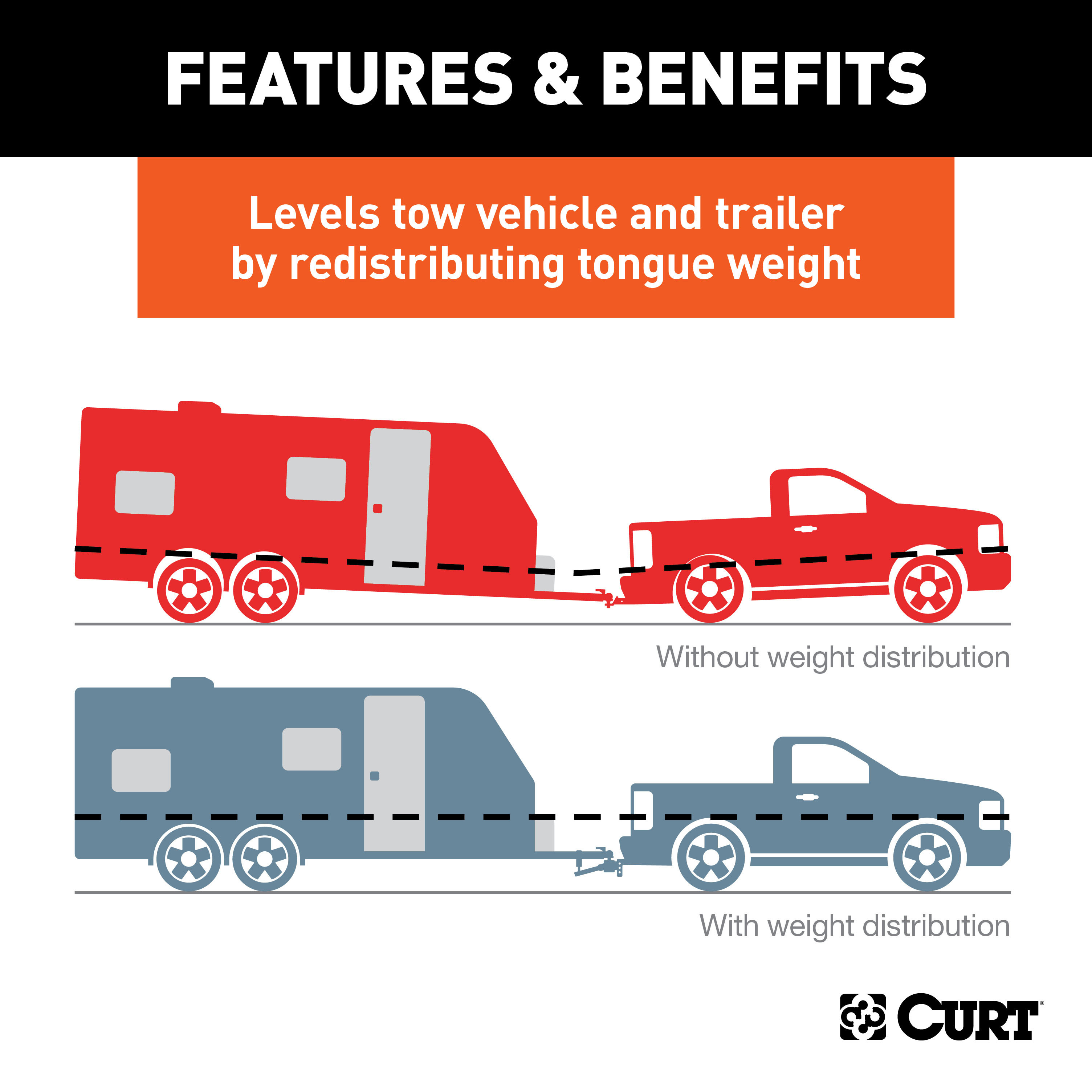
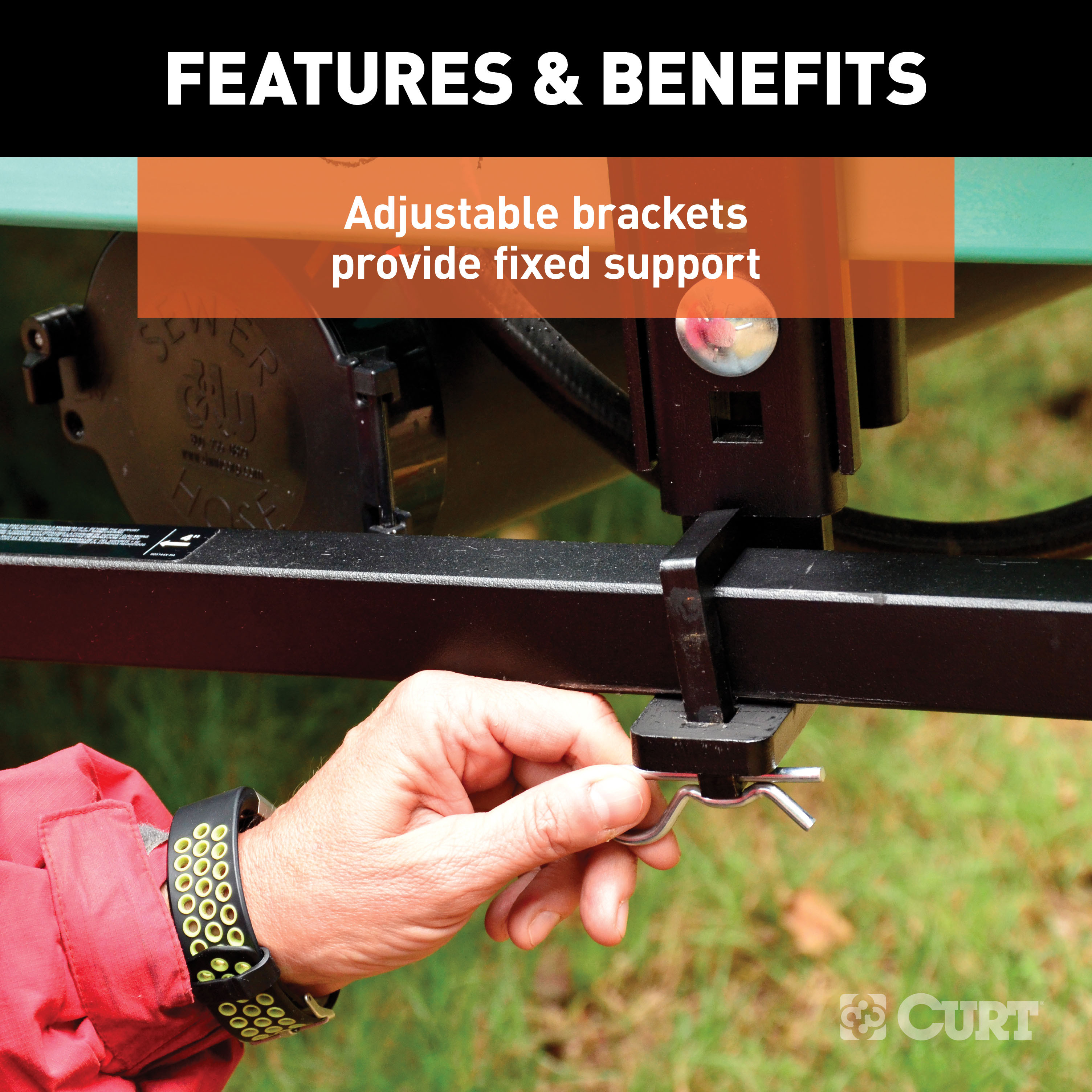
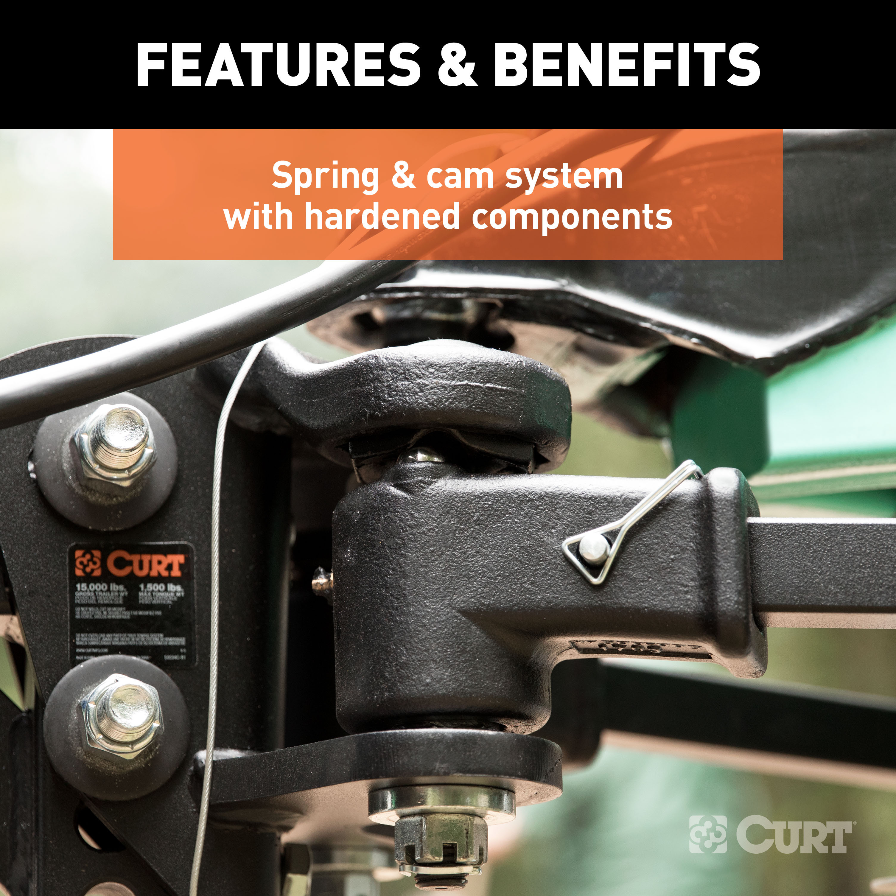
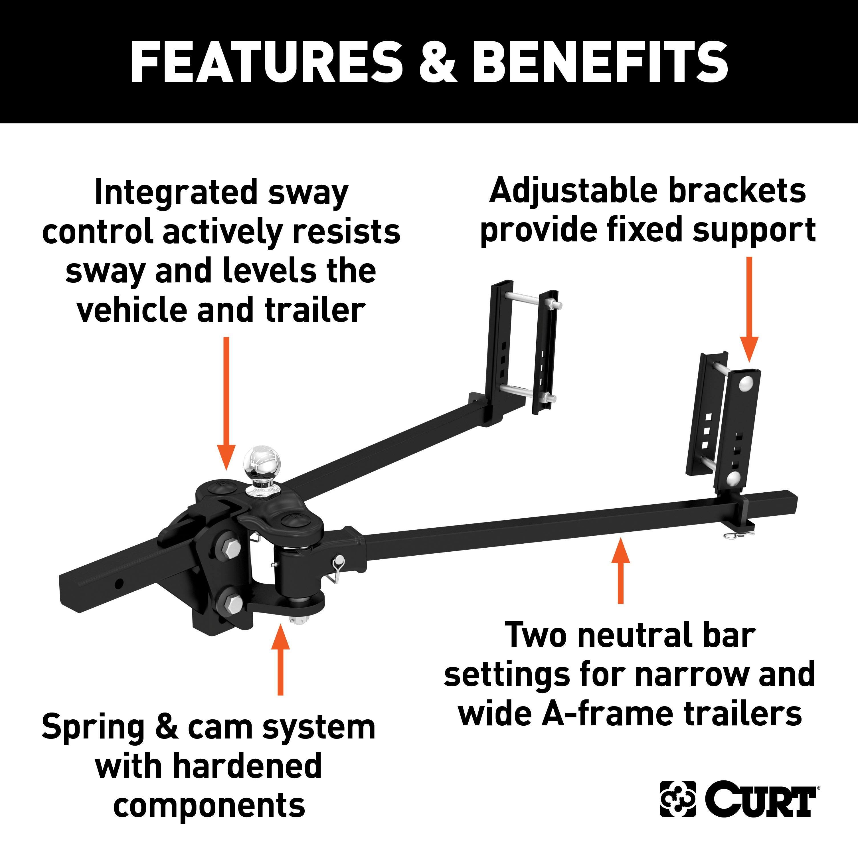
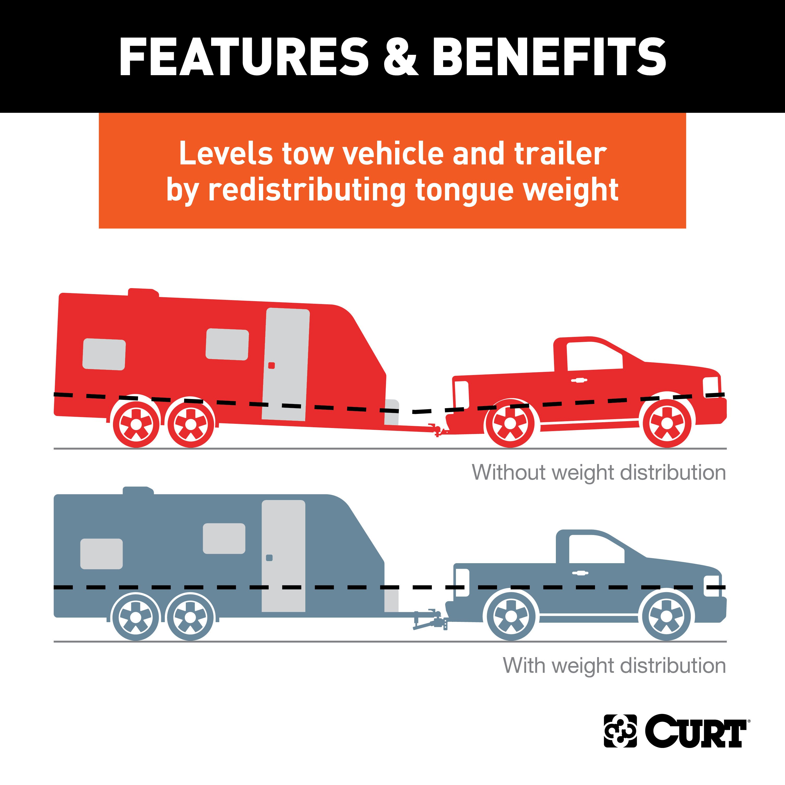
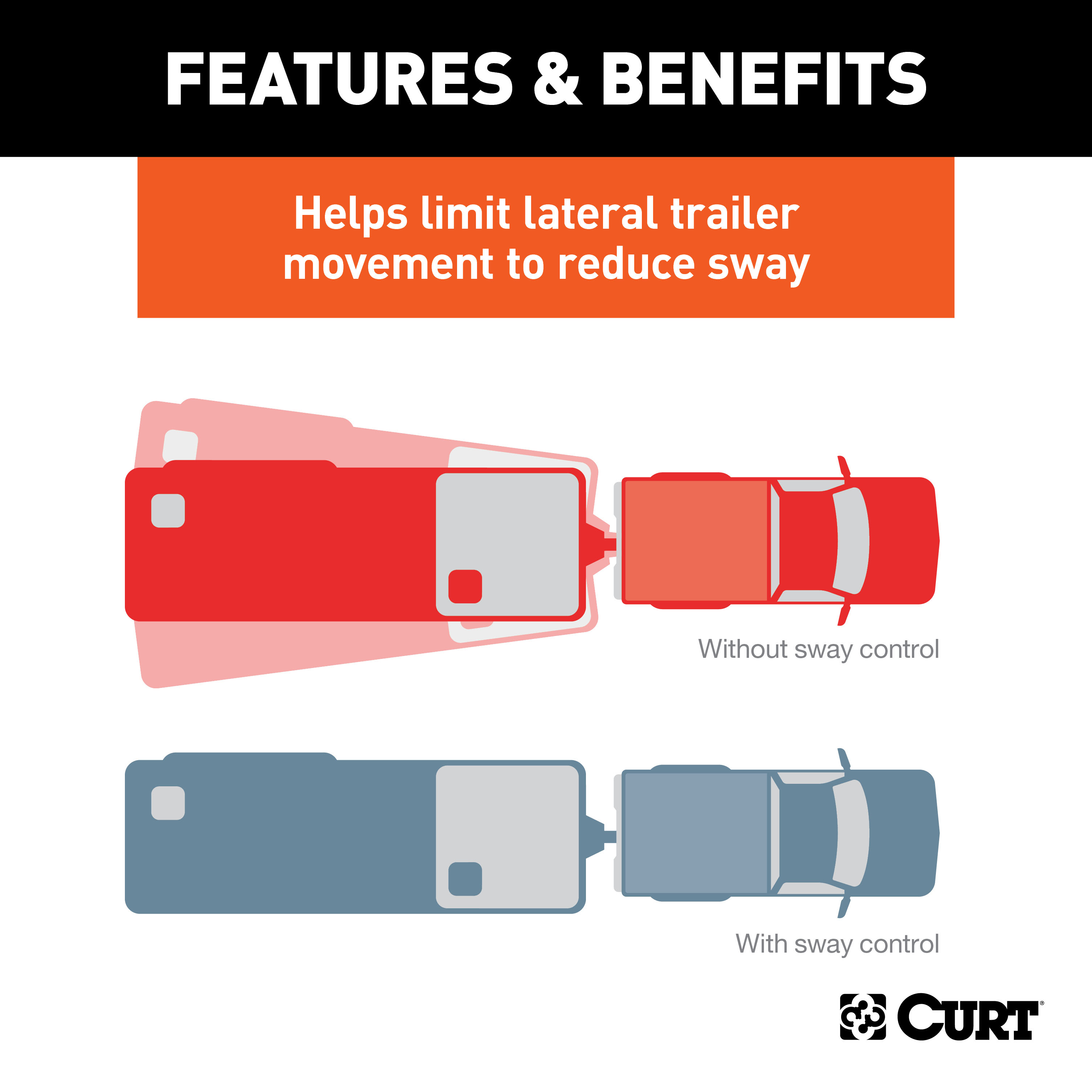
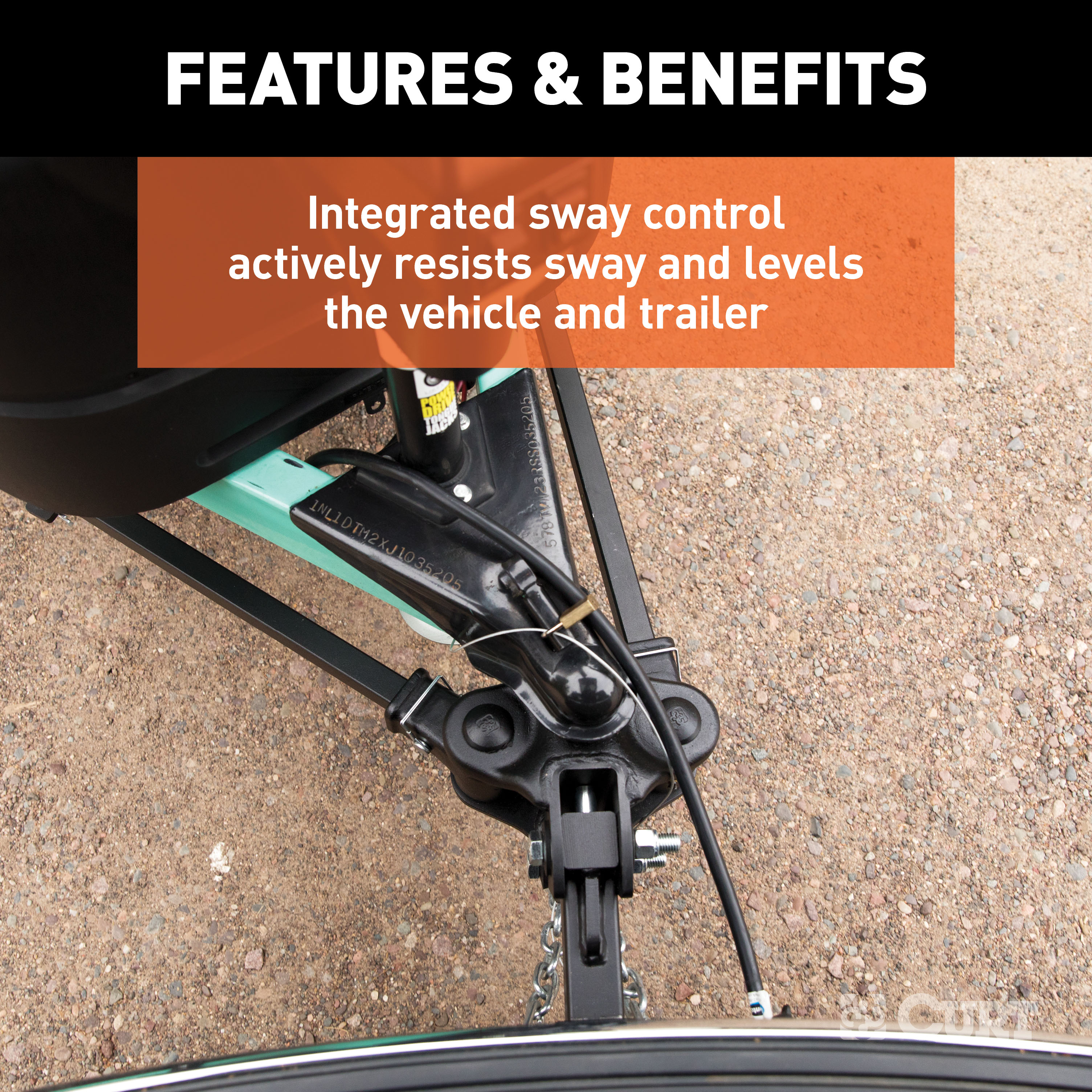
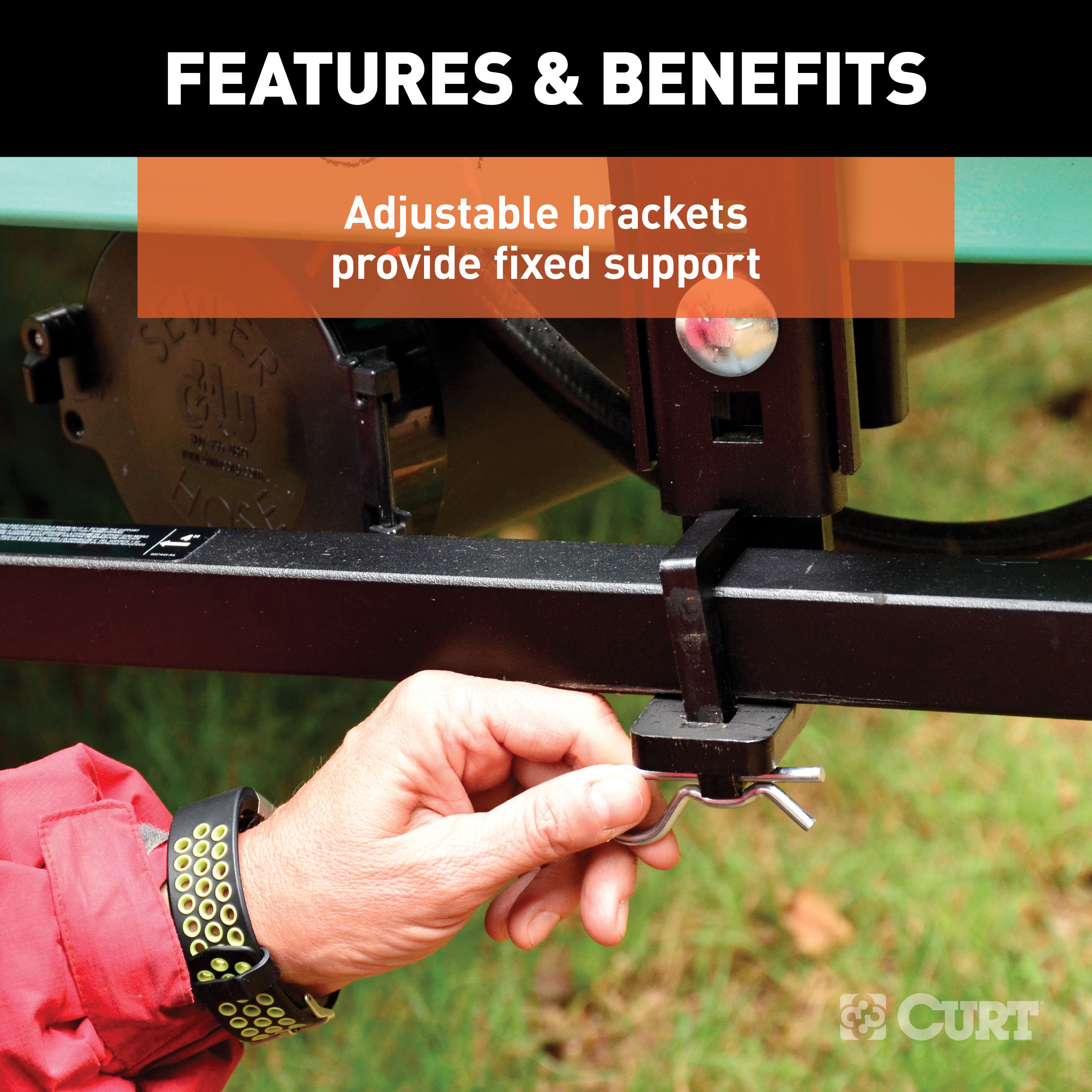
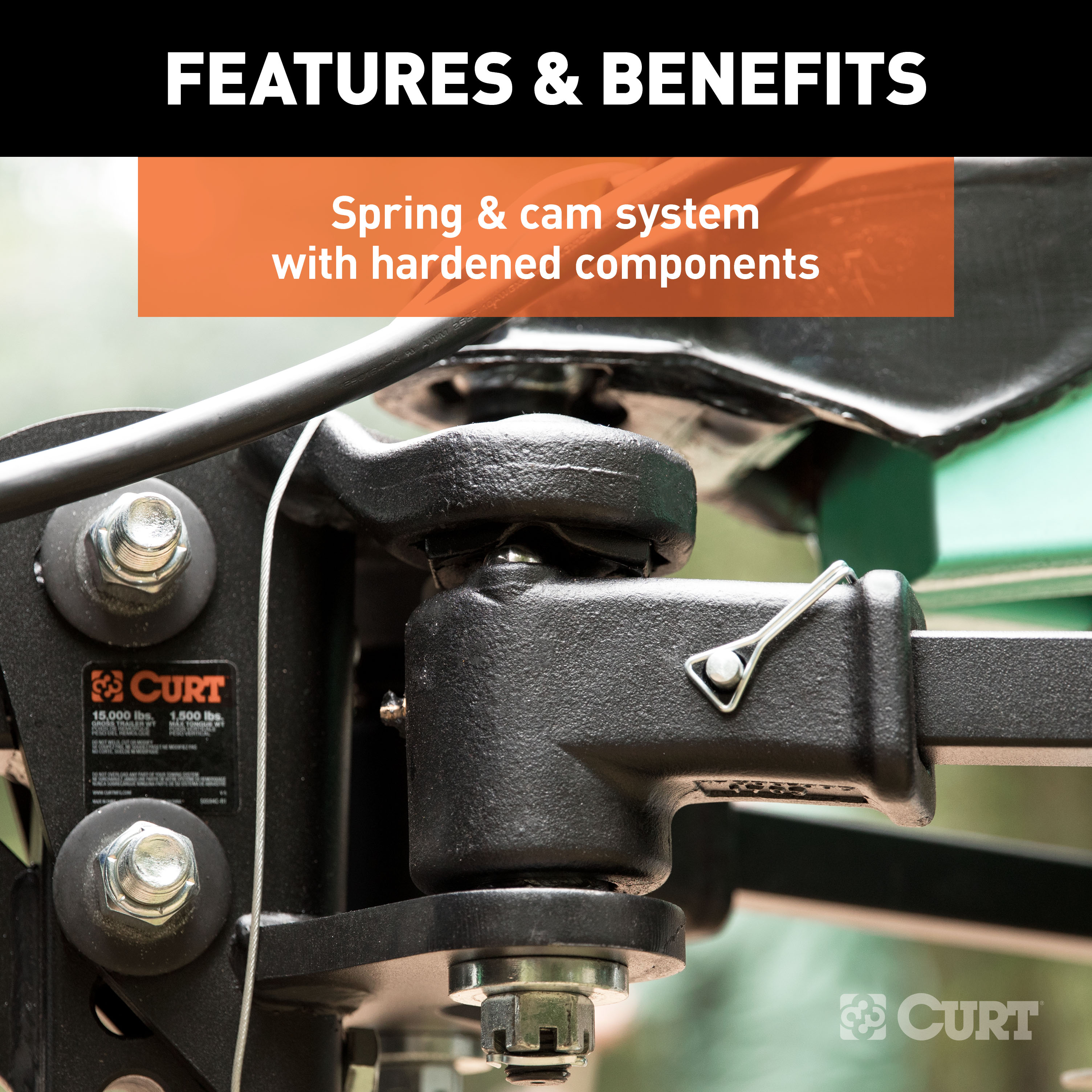
While many weight distribution hitches are made to be compatible with a sway control attachment, the CURT TruTrack is an advanced WD system that integrates the sway control function into the design of the hitch. It combines precise weight distributing with active sway control to deliver the smoothest, safest ride possible. The TruTrack 4P features a unique spring and cam system within the hitch head that builds up pressure to actively stop sway and then relaxes to make smooth turns. The hardened cam components are less subject to wear and last longer than competitor models. The TruTrack also features unique spring bars. Like all WD hitches, it uses a pair of spring bars to leverage the trailer tongue weight and spread it across all axles of the vehicle-trailer combination. However, instead of using spring bar chains, the TruTrack connects to the trailer frame using heavy-duty, adjustable support brackets that hold the spring bars in place laterally and vertically. While regular spring bars angle from side to side, the integrated sway control arms resist this movement and keep the trailer better aligned. In addition to its integrated sway control, the CURT TruTrack offers the same great quality as our other WD hitches, making it the perfect choice for campers, livestock trailers and other heavy-duty trailers. We stand behind this uncompromising hitch, and to prove it, we back it up with a limited lifetime warranty.

CURT offers a variety of high-quality trailer hitches and accessories for select vehicle models. Find the perfect fit for your towing needs at TowUniverse.
CURT, a Lippert brand, offers a complete line of towing products and is the leading manufacturer of custom-fit trailer hitches. We offer the broadest selection of custom-fit hitches, and each one is designed, welded, and coated in Wisconsin.
CURT is also a leader in flat towing products, as well as 5th wheel, gooseneck, and weight distribution hitches, ball mounts, electrical components, cargo solutions, and other towing accessories.
For everything from passenger cars and vans to full-size pickups and SUVs, CURT is 'The First Name in Towing Products®.'

Experts available to answer your questions
Call 888-634-9494Rediscover "Us" Time | Tested. Proven. Safe. Towing Products
The CURT 17501 TruTrack is designed for A-frame trailers. It is compatible with cars, vans, and small SUVs. Confirm your trailer has an A-frame coupler and that your tow vehicle does not exceed the manufacturer's towing capacity. The hitch accommodates trailers with spring bar angles between 30° and 70° (±5°).
Without spring bars: 15,000 lbs gross trailer weight (GTW) and 1,500 lbs tongue weight (TW). With spring bars: 10,000–15,000 lbs GTW and 1,000–1,500 lbs TW. Do not exceed the trailer ball manufacturer's weight rating. Always use a pair of spring bars rated the same.
Required tools: ratchet, socket set, torque wrench, and tape measure. Installation is rated as moderate difficulty and may vary depending on installer expertise, vehicle condition, and tool availability.
Yes, if your vehicle has air springs, air shocks, or automatic leveling systems, deflate them to their minimum recommended pressure before assembling and adjusting the hitch. Refer to your vehicle owner's manual for specific deflation procedures.
Castle nuts on the spring bar sockets: 75 lb-ft. L-bracket nylock nuts: 25 lb-ft. All other hardware (3/4" hex bolts and head-to-shank fasteners): 200 lb-ft when fully torqued after ride height is achieved.
Before each tow, check: hitch pin & clip (securing shank to receiver), head-to-shank fasteners, trailer ball nut, coupler latch, spring bar support brackets, safety chains, lights and turn signals, and braking system (including breakaway switch). Apply grease to the grease zerk and inner/outer ball bearings before each use.
Keep socket-mounted ends of spring bars and lock pins free from dirt and well lubricated. Keep the head assembly exterior clean and prevent dirt or stones from lodging between spring bars and head. Keep hitch parts painted to prevent rust; do not paint over labels. Keep lift brackets clean and lubricated. Grease the zerk and ball bearings before each use.
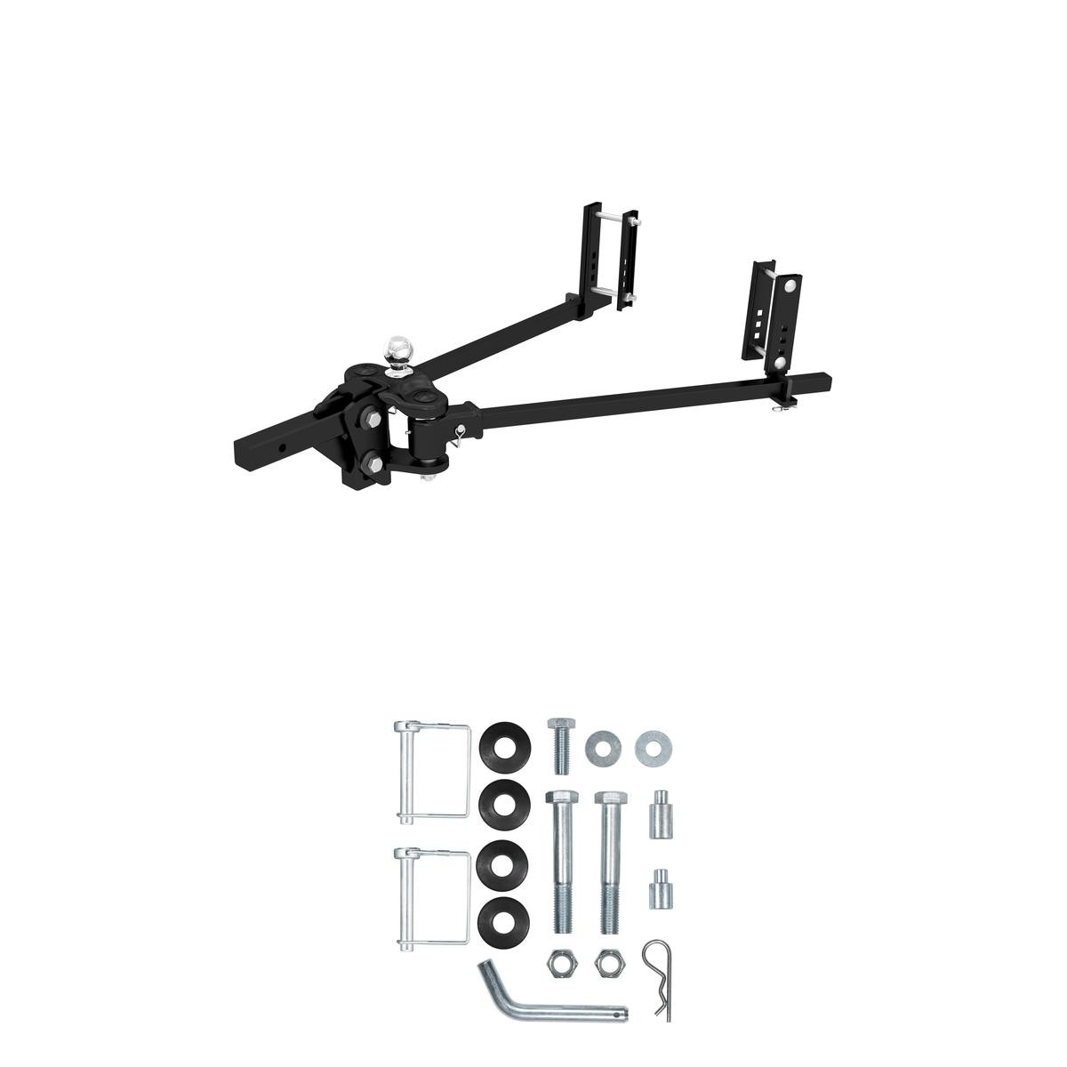
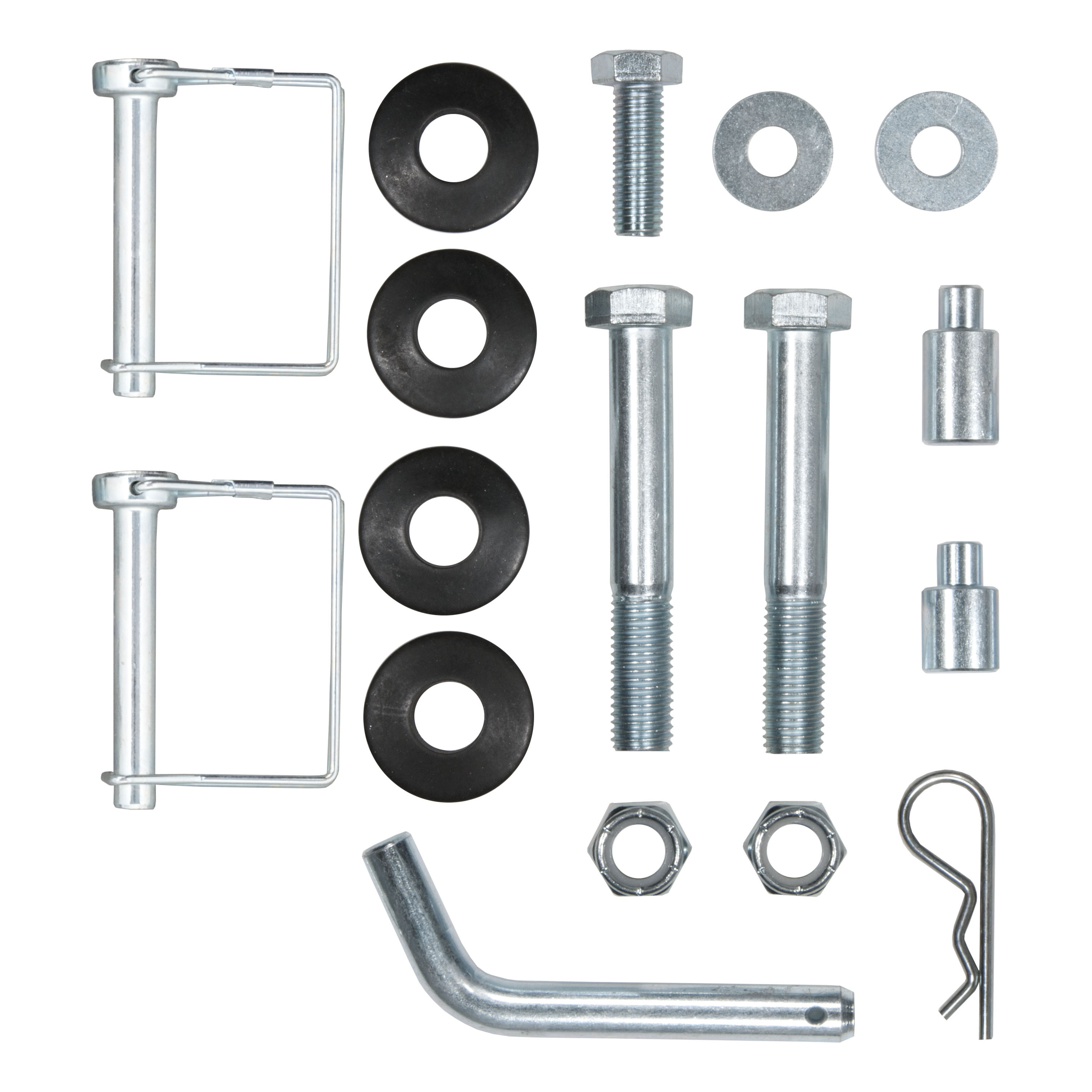
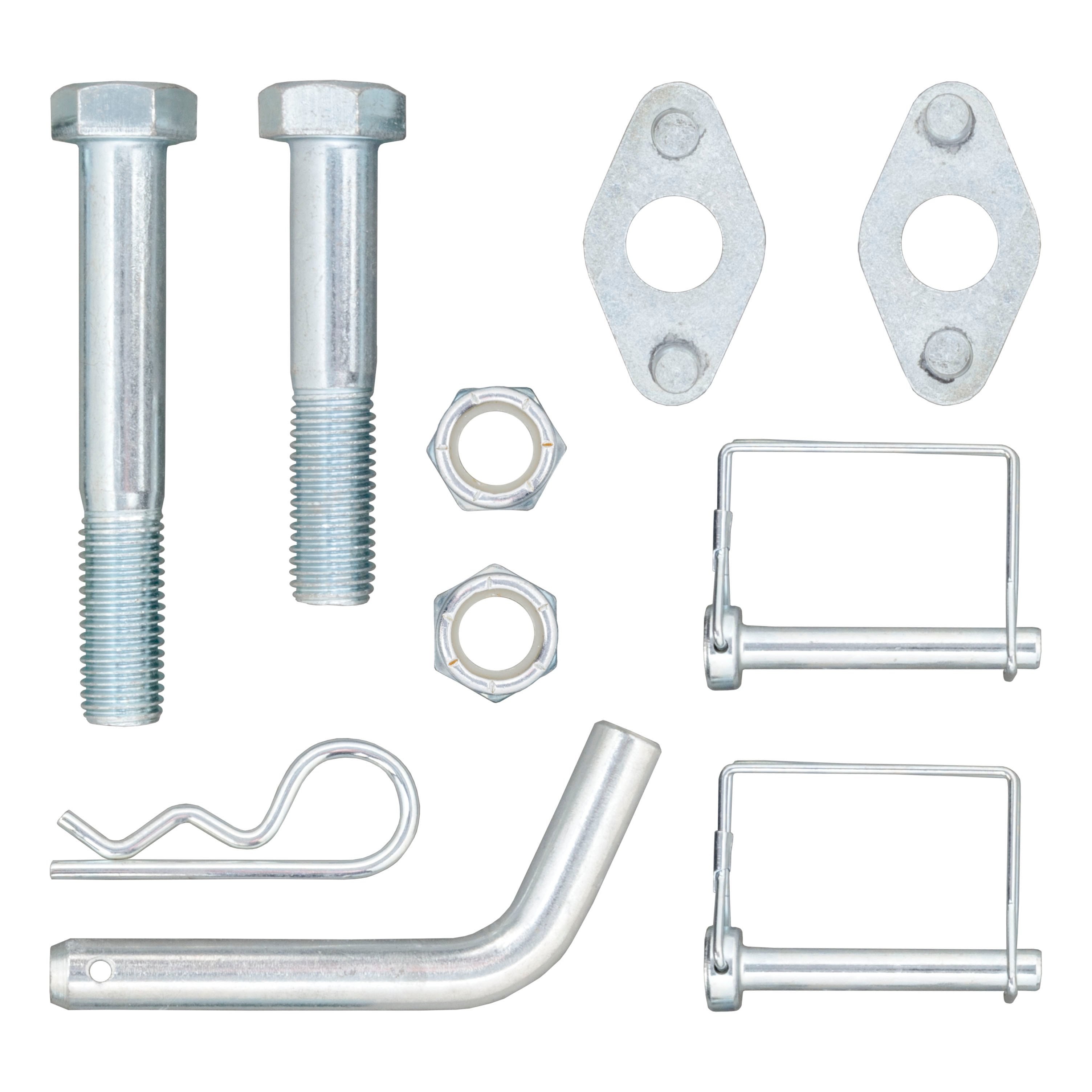
The kit includes: hitch head, adjustable shank, 2 spring trunnion bars, 2 spring bar support brackets, snap-up handle, 2 hex bolts (3/4"-10 x 5"), 4 conical-toothed washers (3/4"), 2 nylock nuts (3/4"-10), 2 wire lock lynch pins, hitch pin & clip (5/8"), short and long adjustment rods, 2 flat washers (1/2"), and 1 hex bolt (5/8"-11 x 1-1/2"). A trailer ball is not included.
Yes, the adjustable shank can be inverted to obtain proper ball height on high-ground-clearance vehicles. If the shank is used inverted, you must check for adequate ground clearance to ensure the shank does not contact the ground or vehicle components.
The CURT 17501 has two neutral spring bar settings: 30° (preset for narrow frames) and 70° (for wider frames). For trailers with A-frame angles of 50° or less, no adjustment is needed—the hitch comes preset in the narrow (30°) setting. For frames over 50°, you must adjust the cam blocks to the 70° position. Adjustment involves removing cotter pins, castle nuts, springs, bushings, and carriage bolts; rotating the cam block outward; and reassembling with the same sequence.
1. Remove cotter pins from castle nuts. 2. Remove castle nuts, bushing sleeves, and springs. 3. Remove carriage bolts while holding the socket in place. 4. With the head upside down, carefully remove the socket with bushing and balls. 5. Pull the cam block out and rotate it outward to the next position (30° to 70° or vice versa). 6. Reinstall in reverse order: socket with bushing and balls, carriage bolts, springs, bushing sleeves, and castle nuts. 7. Torque castle nuts to 75 lb-ft and reinstall cotter pins. 8. Grease with white lithium grease in the zerk.
Line up the tow vehicle and trailer on level pavement in a straight position. Use the trailer tongue jack to level the trailer. Measure the distance from the pavement to the top of the coupler socket. Record this measurement—it is used to determine the target uncoupled ball height for your tow vehicle.
The uncoupled ball height must be set higher than the coupler height to allow for vehicle squat when coupled to the trailer. For cars, vans, and small SUVs, add 1/8" to the coupler height for each 100 lbs of tongue weight. For example, if the coupler height is 16" and tongue weight is 1,000 lbs, add 1.25" (10 × 1/8"), making the target uncoupled ball height 17.25".
Slide the hitch head up or down on the adjustable shank to the nearest bolt hole alignment position that corresponds with the target uncoupled ball height determined in Step 3. Mark this position on the shank. The head will be secured to the shank using hex bolts and adjustment rods in subsequent steps.
1. Place 1/2" flat washers over the short adjustment rod. 2. Insert a 3/4" hex bolt through a 3/4" conical washer. 3. Hold the hitch head at the marked position and insert the assembled bolt and washer through the lower hole in the hitch head channel. 4. Rotate the head forward as far as it will go—the ball should be vertical or tilted slightly back. If not, replace the short rod with the long rod or adjust the number of washers. 5. Place a 3/4" conical washer on the hex bolt and insert it through the upper slotted hole. 6. Install a second 3/4" conical washer on both hex bolts. 7. Start threading 3/4" nylock nuts and tighten until the head is snug and does not tilt on its own. 8. In Step 7, tighten the bolts just enough to hold the rods in place—final torquing to 200 lb-ft occurs after ride height is achieved.
1. Mark the center line on the trailer A-frame 4" in from the end of the spring bars. 2. Place a carriage bolt through the top hole on all three support brackets. 3. Spin the nylock nut loosely onto the bolt and hang the assembly over the trailer A-frame on the center line. 4. Note: The wide channel bracket should be installed over the narrow channel. 5. Slide the L-support between the two captive support brackets. 6. Set the bracket height closest to the spring bar position set with the jack. 7. Install the second carriage bolt in the first hole directly below the trailer A-frame. 8. Tighten both nylock nuts to 25 lb-ft. 9. Repeat for the second support bracket on the opposite side of the trailer A-frame.
1. Pull the spring bar out from the A-frame and hook the lift bar into the L-bracket. 2. Pry the spring bar onto the L-bracket by rotating the lift bar to vertical. 3. With the spring bar supported by the L-bracket, remove the lift handle. 4. Secure the spring bar by installing the retainer clip and cotter pin. 5. Repeat for the second spring bar. Keep clear of the pivot path of all moving parts when there is tension on the spring bar, and maintain control of the lift handle at all times.
1. With the spring bars secured, lower the jack to apply load to the hitch. 2. The vehicle should settle evenly. 3. Remeasure the front and rear bumper reference points (measured in Step 2). 4. If the front has settled much more than the rear, lower the L-brackets to reduce the load on the spring bars. 5. The spring bars should be nearly horizontal when correct height is achieved. 6. If the L-support bracket is in the highest position and you cannot bring the rear of the vehicle to level when load is applied, adjust the head tilt (see Step 17).
If the L-support bracket is in the highest position and the rear of the vehicle cannot be brought to level when load is applied: 1. Uncouple the trailer after removing the load from the spring bars. 2. Remove the top 3/4" hex bolt installed in Step 6. 3. Add washers or replace the short adjustment rod with the long adjustment rod to increase head tilt. 4. Reinstall the 3/4" hex bolt. 5. Repeat Steps 14–16 to ensure proper loaded ride height is achieved. 6. When correct ride height is achieved, fully torque all hardware to 200 lb-ft, including the 3/4" hex bolts.
The loaded ball height must never be greater than the uncoupled ball height. If the loaded trailer ball height is greater than the uncoupled height, front wheel overload and loss of rear wheel traction can result, leading to unstable handling, reduced braking ability, and a tendency to jackknife when turning and braking at the same time. If this occurs, reduce take-up on the spring bar, remeasure, and adjust until the proper height is obtained.
Keep clear of the pivot path of all moving parts when there is tension on the spring bar. Maintain control of the lift handle at all times when raising or lowering the spring bar. Be sure that the locking clip and cotter pin are in place once the spring bar is in position. Never exceed the vehicle manufacturer's recommended towing capacity.
1. Remove the weight from the spring bars by using the trailer jack to lift the front of the trailer and rear of the tow vehicle. 2. With the tension removed from the spring bars, carefully remove the cotter pin and retainer clip. 3. With the spring bar retainer clip removed, use the lift bar as a lever to pry the spring bar off of the L-bracket. 4. Lower the spring bars to the A-frame.
Keep the socket-mounted ends of the spring bars and lock pins in the head assembly free from dirt and well lubricated. Excessive wear in this area may indicate overload or inadequate lubrication. Before each use, apply grease to the grease zerk and brush grease on the inner and outer ball bearings. Use white lithium grease when greasing the zerk during cam block adjustment.
Yes, some states require a clear view of license plates. Remove the trailer ball when not in use if it restricts the view of the license plate.
CURT stands behind the 17501 with industry-leading warranties. To get copies of the product warranty, register your purchase, or provide feedback, visit warranty.curtgroup.com/surveys.
Visit www.curtmfg.com for a full-color copy of the instruction manual, helpful videos, guides, and more. For product support, call 877.287.8634. For towing safety information, visit curtmfg.com/understanding-towing.
This condition causes front wheel overload and loss of rear wheel traction, leading to unstable handling and reduced braking ability. To correct it: 1. Reduce take-up on the spring bar by lowering the L-bracket support. 2. Remeasure the ball height. 3. Adjust until the proper height is obtained (loaded height should not exceed uncoupled height). 4. The spring bars should be nearly horizontal when correct height is achieved.
This indicates excessive load on the spring bars. Lower the L-bracket support brackets to reduce the load on the spring bars. Remeasure the front and rear bumper reference points. The vehicle should settle evenly, and the spring bars should be nearly horizontal when correct height is achieved. If the L-bracket is already in the highest position and the rear still cannot be brought to level, adjust the head tilt (Step 17).
The ball should be vertical or tilted slightly back when the head is rotated forward as far as it will go. If it is not: 1. Remove the short adjustment rod and replace it with the long adjustment rod, or 2. Change the number of washers on the rod and reassemble. This adjustment affects the head tilt and should be made before final torquing.
Excessive wear in the socket-mounted ends of the spring bars and lock pins indicates either overload (exceeding the hitch weight capacity) or inadequate lubrication. Inspect the hitch for signs of overload and ensure the socket-mounted ends and lock pins are kept free from dirt and well lubricated. Apply white lithium grease to the zerk before each use.
If the hitch head tilts on its own after tightening the nylock nuts in Step 6, the bolts are not tight enough. Continue tightening the 3/4" nylock nuts until the head is snug and does not tilt on its own. Do not fully torque to 200 lb-ft at this stage—that occurs only after ride height is achieved in Step 17.

Total for 2 items:
$831.94$1,256.90
| Part # | GTW | TW | Bar Length | Description |
|---|---|---|---|---|
| 17499 | 5,000 - 8,000 lbs. | 500 - 800 lbs. | 35-9/16" | WD system only (trailer ball not included) |
| 17500 | 8,000 - 10,000 lbs. | 800 - 1,000 lbs. | 35-9/16" | WD system (17500) and pre-torqued 2-5/16" trailer ball (40006) |
| 17501 | 10,000 - 15,000 lbs. | 1,000 - 1,500 lbs. | 35-9/16" | WD system (17501) and pre-torqued 2-5/16" trailer ball (40030) |
On Sale Today
Original price was $939.95. Current price is $634.95.You save $305.00 (32%)
Free Shipping
Ships free on all orders
 Authorized Dealer


Quick Ship
In stock and ready to ship — order now!
Shipping from Eau Claire, WIFREE SHIPPING
Estimated delivery Sun, Sep 27 - Tue, Sep 29
Order before 2 PM EST Monday–Friday for same-day processing
Guaranteed safe & secure checkout
No reviews have been added for this product.