Ask a Question About This Product
Our in-house experts typically reply within one business day.
Our in-house experts typically reply within one business day.

CURT
Verify Fitment
Select your vehicle to confirm this part fits.
2017 - 2026 Jaguar F-Pace
Confirmed to Fit







Always the correct part
We know our products
Quality Products
Free Shipping!
Always the correct part
We know our products
Quality Products
Free Shipping!

CURT offers a variety of high-quality trailer hitches and accessories for select vehicle models. Find the perfect fit for your towing needs at TowUniverse.
CURT, a Lippert brand, offers a complete line of towing products and is the leading manufacturer of custom-fit trailer hitches. We offer the broadest selection of custom-fit hitches, and each one is designed, welded, and coated in Wisconsin.
CURT is also a leader in flat towing products, as well as 5th wheel, gooseneck, and weight distribution hitches, ball mounts, electrical components, cargo solutions, and other towing accessories.
For everything from passenger cars and vans to full-size pickups and SUVs, CURT is 'The First Name in Towing Products®.'
Experts available to answer your questions
Call 888-634-94941 compatible vehicles
| Year | Make & Model | Notes |
|---|---|---|
| 2017 - 2026 | Jaguar F-Pace | — |
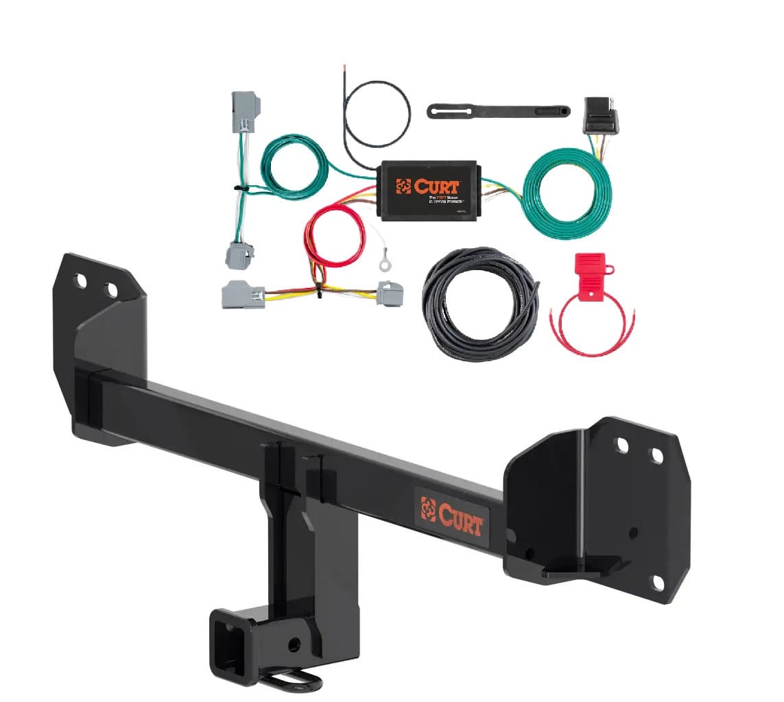
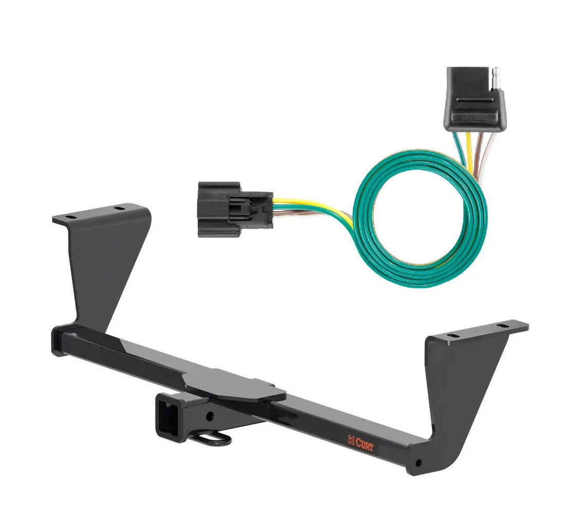
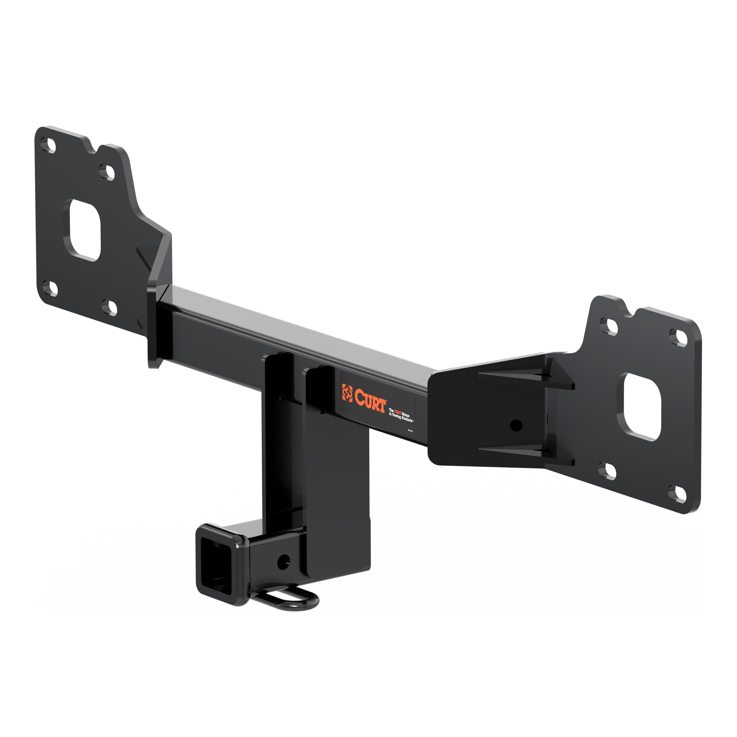
Yes, CURT part number 13291 is designed for 2017-Present Jaguar F-PACE CUV models. Confirm your vehicle year and model match this range before purchasing.
The CURT 13291 is rated for a maximum trailer weight of 6,000 lbs and tongue weight of 900 lbs when used as a weight-carrying hitch. You must never exceed your vehicle manufacturer's recommended towing capacity, which may be lower than the hitch rating.
Required tools are: ratchet, torque wrench, 6-inch socket extension, 8mm socket, 10mm socket, 21mm socket, T25 torxbit socket, plastic pry tool, screwdriver, masking tape, aviation shears, and safety glasses. Proper tools will greatly improve installation quality and reduce installation time.
Two people may be required to ease installation. If you are hesitant to undertake this task on your own, contact an authorized CURT installer for additional assistance. You can reach CURT technical support at 877-287-8634.
Professional installation time is 120 minutes. Novice (DIY) installation time is 60 minutes. Actual time may vary depending on your experience and familiarity with the vehicle.
Yes, trimming is required. You must mark out and trim a 3.25-inch by 6-inch section of the underbody panel using masking tape and aviation shears. These dimensions are approximate; confirm the exact section prior to reinstallation. The trimmed panel is set aside for later reinstallation.
On the underbody panel, remove 3 screws using a 10mm socket and 4 screws using a screwdriver. After removal, mark and trim the 3.25-inch by 6-inch section, then set the panel aside for later reinstallation.
Inside the wheel well, locate and remove 2 screws using a screwdriver. Once removed, pull back the wheel well to reveal 5 additional screws. Remove 2 of these screws using a T25 torxbit socket and 3 using a screwdriver. Set the wheel well accent piece aside for later reinstallation.
Locate and remove the plastic cover next to each tail light, revealing 1 screw on each side. Remove these screws using an 8mm socket. Locate 1 plastic screw on each side and remove using a screwdriver. Use a plastic pry tool to remove the remaining plastic push pins. Set all pieces aside for later reinstallation.
Gently remove the bumper fascia starting at the outside of the vehicle and working towards the rear. Locate and unplug 2 electrical plugs on the bumper fascia. Set the fascia aside for later reinstallation.
The bumper beam is secured with 8 M14 bolts (4 on each side) that attach to existing weld nuts on the vehicle frame. These bolts are removed and reused to attach the hitch. You will also remove 5 screws along the panel using an 8mm socket.
The 8 M14 bolts must be torqued to 126 ft-lbs. First, loosely fasten all bolts while lining up the hitch holes with the bumper beam holes, then torque them to the specified value.
Use a 21mm socket to remove and install the 8 M14 bolts (4 on each side of the bumper beam).
Reinstall following steps 1-5 in reverse order. This means: reinstall the bumper beam and panel fasteners, reconnect the bumper fascia electrical plugs and reinstall the fascia, reinstall the tail light area covers and screws, reinstall the wheel well accent piece and screws, and finally reinstall the underbody panel and trim.
Safety glasses must be worn at all times while installing this product. Before you begin installation, read all instructions thoroughly. Using proper tools will greatly improve the quality of the install and reduce the time required.
All non-trailer loads applied to this product must be supported by CURT 18050 stabilizing straps. Failure to properly support non-trailer loads will void the product warranty.
Periodically check the receiver hitch to ensure all fasteners are tight and all structural components are sound. This ongoing inspection helps maintain the integrity and safety of the installation.
CURT Manufacturing warrants this product to be free of defects in material and/or workmanship at the time of retail purchase by the original purchaser. If the product is found to be defective, CURT may repair or replace it at their option when returned prepaid with proof of purchase. Alteration to, misuse of, or improper installation voids the warranty.
The CURT 13291 complies with safety specifications and requirements for connecting devices and towing systems of the state of New York, V.E.S.C. Regulation V-5 and SAE J684.
The CURT 13291 is designed for 2017-Present Jaguar F-PACE CUV models only.
Maximum trailer weight is 6,000 lbs and tongue weight is 900 lbs. Never exceed your vehicle manufacturer's recommended towing capacity.
Yes, you must trim a 3.25-inch by 6-inch section of the underbody panel using aviation shears. The trimmed panel is reinstalled after hitch installation.
You need: ratchet, torque wrench, 6-inch socket extension, 8mm/10mm/21mm sockets, T25 torxbit socket, plastic pry tool, screwdriver, masking tape, aviation shears, and safety glasses.
The 8 M14 bolts must be torqued to 126 ft-lbs using a 21mm socket.
Professional installation: 120 minutes. Novice (DIY) installation: 60 minutes.
Safety glasses must be worn at all times during installation.
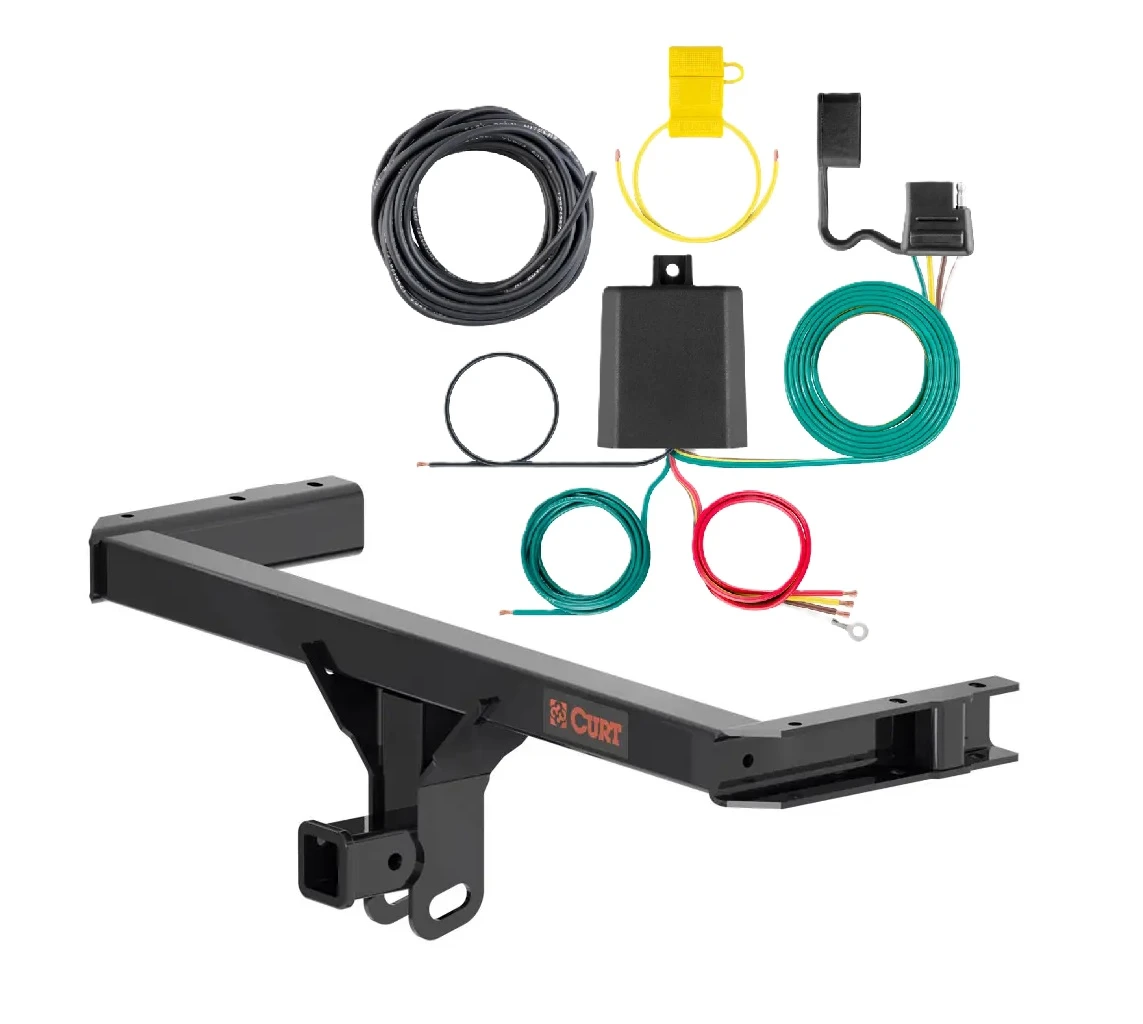
The CURT 59236 is a powered taillight converter that converts your vehicle's taillight signals to a 4-flat trailer connector. It allows you to connect a trailer with a 4-flat plug to your vehicle's existing taillight wiring. The converter reads your vehicle's brake, turn, and tail light signals and outputs them through the 4-flat connector for the trailer to use.
The CURT 59236 is designed for SUVs, vans, passenger cars, and trucks with 12-volt negative ground electrical systems. The manual provides wiring location guides for three vehicle types: SUVs and vans (S), passenger cars (P), and trucks (T). You must verify your vehicle has a 12-volt negative ground system before installation. Consult your vehicle's owner's manual to confirm your electrical system type.
The CURT 59236 works with four vehicle wiring types: two-wire (combined stop and turn signal with independent tail signal), three-wire (independent stop, turn and tail signals), PWM-ST (combined stop and tail signal with independent turn signal), and PWM-STT (combined stop, turn and tail signal). You must identify your vehicle's wiring type before installation by probing the taillight connectors with a multimeter or test light while activating each light circuit. The manual provides a detailed chart on page 2 to help you determine your vehicle's wiring type.
Required tools are: test light, utility knife, electrical tape, wire crimper, paper, wire stripper, and pen. You may also need a multimeter (as an alternative to a test light) to determine your vehicle's wiring type. A drill with a 3/32" bit is needed if you must create a new grounding point, and a screwdriver is required to secure the ground wire. Proper tools will improve installation quality and reduce installation time.
The CURT 59236 includes: a black converter box, a white ground wire with ring terminal, a 12-gauge power wire with ring terminal, snap locks for connecting input wires to vehicle harness, provided cable ties, double-sided tape for mounting the converter, a screw for the ground wire connection, a 4-flat dust cover, and a fuse holder with 15-amp maximum fuse. The manual shows a hardware photo on page 1 for reference.
Yes, you must disconnect the negative battery terminal before beginning installation. This is a required safety step. Look up the battery location in your vehicle's owner's manual. Be sure to fasten the disconnected negative wire down and away from the battery during the installation process. Reconnect the negative battery terminal only after all other installation steps are complete.
With the vehicle running and all lights off at the back, probe the taillight connectors (still connected to the vehicle) using a multimeter set to DC volts or a test light. Ignore any wires carrying less than two volts (multimeter) or that do not illuminate the test light bulb. Then activate each light circuit (left turn, right turn, brakes, tail) one at a time and probe the remaining wires. Match your results to the chart on page 2 titled 'Determining Vehicle Wiring Types' to identify whether your vehicle is two-wire, three-wire, PWM-ST, or PWM-STT. This determines which converter wires connect to which vehicle wires.
Use the snap locks provided to attach the converter's input wires to your vehicle's taillight harness wires. The connection depends on your vehicle's wiring type. For two-wire systems: green wire to right stop/turn, red wire to ground (white wire), yellow wire to left stop/turn, brown wire to tail. For three-wire: green to right turn, red to stop, yellow to left turn, brown to tail. For PWM-ST: green to right turn, red to stop/tail, yellow to left turn, brown to ground. For PWM-STT: green to right turn/stop/tail, red to ground, yellow to left turn/stop/tail, brown to ground. Refer to the Wiring Installation table on page 3.
Mount the black converter box on a flat spot inside the vehicle near the taillight using the provided double-sided tape. The area should be clean and suitable for adhesive mounting. Ensure the location allows easy access to the wires and does not interfere with vehicle operation or maintenance.
Locate a suitable grounding point near the converter, such as an existing screw with nut in the vehicle frame. The area must be free of rust, dirt, and paint. Secure the white ground wire using the ring terminal and the provided screw. If no suitable existing screw is available, drill a 3/32" pilot hole in a clean area of the vehicle frame and use the provided screw. Before drilling, check for hidden items behind or under any surface to avoid damage and personal injury.
Route the 12-gauge power wire from the converter to the vehicle battery location, avoiding pinch points and hot or rotating components. Use existing grommets or add a grommet when passing the wire through sheet metal to protect it from sharp edges; alternatively, use silicone for protection. At the battery, attach the ring terminal of the black power wire to the positive (+) battery terminal using a butt connector. Install the fuse holder with a 15-amp maximum fuse after all other steps are complete. The battery connection must be fuse-protected with a maximum 15-amp fuse to prevent overheating and potential fire.
Install the 15-amp fuse in the fuse holder only after all other installation steps are complete. This is the final step before testing. The fuse protects the battery connection and converter from overcurrent. Do not exceed a 15-amp fuse rating.
When in use, route the 4-flat connector to the center of the vehicle and out of the trunk. When not in use, roll up the connector and store it in a convenient, out-of-the-way location inside the trunk. Secure any loose wires with the provided cable ties to prevent tangling and damage. Install the provided 4-flat dust cover to help prevent corrosion.
Drilling is required only if you cannot find a suitable existing grounding point (such as an existing screw with nut in the vehicle frame) near the converter. If you must drill, create a 3/32" pilot hole in a clean area of the vehicle frame free of rust, dirt, and paint. Before drilling, check for hidden items behind or under any surface to avoid damage and personal injury. The modification is permanent.
The CURT 59236 has the following electrical ratings: signal circuits (left and right turn) are rated at 5.0 amps per side, and tail/running circuits are rated at 7.5 amps total. Do not exceed the product rating or your tow vehicle's lamp load rating, whichever is lower. Exceeding the product rating can cause loss of warranty, overheating, and potential fire. The product is designed for 12-volt negative ground systems only.
The power wire is 12-gauge (12 GA) or larger. This wire connects from the converter to the vehicle battery and must be routed carefully to avoid pinch points and hot or rotating components.
The maximum fuse rating is 15 amps. The battery connection must be fuse-protected with a 15-amp maximum fuse. Do not use a fuse larger than 15 amps, as exceeding the product rating can cause loss of warranty, overheating, and potential fire.
The converter has four input wires: green (right turn), red (brake), yellow (left turn), and brown (taillight). These wires connect to your vehicle's corresponding taillight signals using snap locks. The white ground wire connects to vehicle ground. The black power wire connects to the vehicle battery positive terminal. The specific connections depend on your vehicle's wiring type (two-wire, three-wire, PWM-ST, or PWM-STT).
Test the converter using either a test light or a trailer. With a test light: attach the ground lead to the exposed ground terminal of the 4-flat end, then activate the tow vehicle's left turn, right turn, tail, and brake lights one at a time. Probe the three receptacles of the 4-flat end to confirm proper functionality. With a trailer: mate the 4-flat with the trailer and run the same test using the trailer lights. If a trailer light function does not work, disconnect the trailer 4-flat, turn vehicle functions off, and recheck with a test light. If the test light shows good functionality, the issue is with the trailer, not the converter.
Do not exceed the CURT 59236 product rating or your tow vehicle's lamp load rating, whichever is lower. The product has signal circuit ratings of 5.0 amps per side and tail/running circuit ratings of 7.5 amps total. Exceeding these ratings can cause loss of warranty, overheating, and potential fire. Consult your vehicle owner's manual or contact the vehicle manufacturer for your vehicle's lamp load rating.
Before drilling, check for miscellaneous items that may be hidden behind or under any surface to avoid damage and personal injury. This includes fuel lines, electrical wiring, brake lines, and other components that could be damaged if drilled through. Take time to inspect the area thoroughly before making any holes.
When passing the 12-gauge power wire through sheet metal, use an existing grommet, add a new grommet, or apply silicone to protect the wire from sharp edges. This prevents the wire insulation from being cut or abraded, which could cause a short circuit or fire hazard.
After installation, perform the following checks: (1) Test the converter using a test light or trailer to confirm all light functions work properly (left turn, right turn, brake, tail). (2) Verify that the converter box is securely mounted with double-sided tape. (3) Confirm the ground wire is securely fastened with the ring terminal and screw. (4) Check that the power wire is properly routed and secured with cable ties, avoiding pinch points and hot components. (5) Verify the 15-amp fuse is installed in the fuse holder. (6) Ensure all loose wires are secured with cable ties. (7) Reinstall all items removed during installation.
Periodic inspection of all wires and connections should be performed to ensure there is no visible damage or loose connections. Check the converter box mounting, ground wire connection, power wire routing, and all snap lock connections. Look for signs of corrosion, especially on the 4-flat connector. Install and maintain the provided 4-flat dust cover to help prevent corrosion when the connector is not in use.
Pulsing trailer lights every two seconds indicate that the lamp circuits exceed the product's ratings (5.0 amps per side for signals, 7.5 amps total for tail/running) or there is a wiring issue with the trailer. The converter's short circuit, overload, and thermal protection activate to prevent damage. Check that your vehicle's lamp load does not exceed the converter's ratings. If the vehicle lights are within rating, disconnect the trailer and inspect its wiring for faults or excessive lamp loads.
First, disconnect the trailer 4-flat connector from the vehicle. Turn off the corresponding light function on the vehicle (left turn, right turn, brake, or tail). Use a test light to probe the 4-flat receptacles to check if the converter is sending the signal. If the test light shows the signal is present, the problem is with the trailer wiring or lights, not the converter. If the test light shows no signal, recheck your vehicle wiring type identification and verify that the converter input wires are correctly connected to the vehicle taillight harness using the Wiring Installation table on page 3.
Check that the 15-amp fuse is installed in the fuse holder and is not blown. Verify that the black power wire is securely connected to the vehicle battery positive (+) terminal using the ring terminal and butt connector. Confirm that the white ground wire is securely fastened to a clean, rust-free grounding point on the vehicle frame using the ring terminal and screw. Ensure the negative battery terminal is reconnected. If the fuse is blown, check for a short circuit in the power wire routing or a wiring error in the converter connections.
The CURT 59236 fits SUVs, vans, passenger cars, and trucks with 12-volt negative ground electrical systems. You must identify your vehicle's wiring type (two-wire, three-wire, PWM-ST, or PWM-STT) using the test procedure on page 2 before purchase. Consult your vehicle owner's manual to confirm your electrical system type.
Yes, you must disconnect the negative battery terminal before beginning installation and reconnect it only after all other steps are complete.
Perform periodic inspection of all wires and connections to ensure no visible damage or loose connections. Maintain the 4-flat dust cover to prevent corrosion.
On Sale Today
Original price was $611.90. Current price is $430.34.You save $181.56 (30%)
Free Shipping
Ships free on all orders
 Authorized Dealer
Quick Ship
In stock and ready to ship — order now!
FREE ShippingFREE SHIPPING
Estimated delivery Thu, Sep 17 - Sun, Sep 20
Order before 2 PM EST Monday–Friday for same-day processing
Guaranteed safe & secure checkout
No reviews have been added for this product.