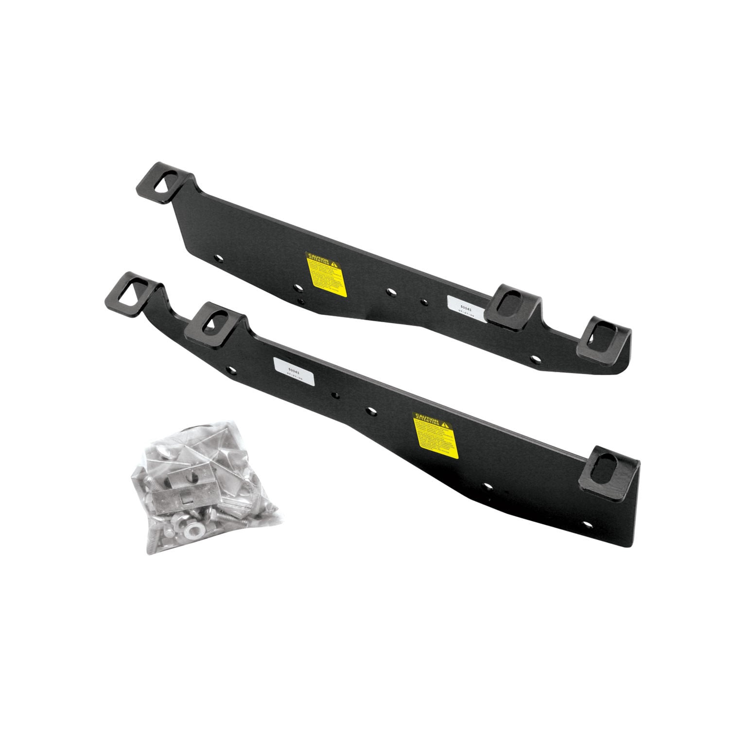
Reese Fifth Wheel Hitch Mounting System Custom Bracket RE50043ReeseOriginal price was $181.25. Current price is $147.71.Out of Stock
View productOur in-house experts typically reply within one business day.

Reese
Verify Fitment
Select your vehicle to confirm this part fits.
2007 - 2021 Toyota Tundra
Confirmed to Fit

Always the correct part
We know our products
Quality Products
Free Shipping!
Always the correct part
We know our products
Quality Products
Free Shipping!

Want to take the family on a cross-country adventure? Or perhaps you're planning a shorter trip to your favorite campground. Whatever your destination, it's important to have the right equipment, especially when towing a fifth wheel trailer. To ensure proper hookup and safety while towing, you'll need something to attach your fifth wheel hitch in the bed on your truck. Many pickups come equipped with factory-installed rails or puck systems, but if you don't have one of these already installed, don't worry. REESE has an extensive line of mounting rails and bracket kits, custom-made to the exact specifications needed based on your truck's year, make, and model. REESE also offers several Industry Standard designs, as well as fastener kits, spacer kits, and a Power Puck mounting kit, so you can be sure you're covered, no matter what pickup you're using to tow. So make it easy. Make it fun. Make it REESE, so you can make the journey as enjoyable as the destination.
| BRAND: | REESE |
| PART NUMBER: | 50084 |
| WARRANTY: | LIMITED 10 YEAR WARRANTY |
| WEIGHT: | 32.85 LBS |
| UNIVERSAL OR SPECIFIC FIT: | SPECIFIC |
| WELDING REQUIRED: | NO |
| MOUNTING HARDWARE INCLUDED: | YES |
| RAILS INCLUDED: | NO |
| DRILLING REQUIRED: | YES |
| MATERIAL: | STEEL |
| BOLT GRADE: | GRADE 5 |
| LOCKABLE: | NO |
| COLOR: | BLACK |

Reese has designed towing equipment since 1952 and remains a benchmark for heavy-duty towing. The line covers fifth wheel hitches such as the modular M5, gooseneck couplers including the Goose Box, air-ride and short-bed pin boxes, weight distribution systems with active sway control, and the accessories that connect them, all built to exceed published industry standards.
Reese has been pioneering towing performance since 1952, when Margaret Reese asked her husband TJ to stop travel trailers rocking every time somebody walked through them. His answer, the first pair of stabilising jacks, was simple and effective enough to change the RV industry. From that starting point Reese grew into a designer and manufacturer of complete towing systems, and today it anchors the heavy-duty end of the Horizon Global towing portfolio.
Fifth wheel towing is where the brand's engineering is most visible. The M5 fifth wheel hitch uses a modular design that breaks into manageable sections for assembly, with a wider stance, tighter tolerances and a shock absorption system aimed at the jolts that travel up through a truck bed. For owners who would rather tow from a gooseneck coupler and keep the bed clear, the Goose Box 20K replaces the trailer's king pin with a gooseneck connection carrying its own air-ride cushioning.
Pin boxes are a Reese speciality. The 5th Airborne uses air-ride technology to dampen road shock and reduce the chucking motion that makes fifth wheel towing tiring, while the Sidewinder was designed for short-bed pickups, pivoting the connection point so the trailer can turn sharply without the front cap meeting the cab.
For conventional towing, Reese weight distribution systems restore load to the tow vehicle's front axle and control sway. The Pro Round Bar distributes weight evenly while damping sway, and the Pro Dual Cam II uses active cam-based sway control that works harder the stronger the sway force becomes. Complete kits pair bars, head and shank to a rated tongue weight, and dedicated sway control kits can be added to existing setups. The products suit RV owners, horse and livestock haulers and anyone towing near the upper end of a vehicle's rating.
Experts available to answer your questions
Call 888-634-949410 Years
1 compatible vehicles
| Year | Make & Model | Notes |
|---|---|---|
| 2007 - 2021 | Toyota Tundra | Fifth Wheel Trailer Hitch Brackets Uses all existing holes. No Drilling required Install Time is 0 minutes Custom Quick Install Brackets |
Yes, the Reese Fifth Wheel Hitch Mounting System Custom Bracket RE50084 (Part #RE50084) is designed to fit the 2007-2021 Toyota Tundra.
The Reese Fifth Wheel Hitch Mounting System Custom Bracket RE50084 (Part #RE50084) fits the following vehicles: 2007-2021 Toyota Tundra. Always verify your specific year, make, and model before ordering.
The Reese Fifth Wheel Hitch Mounting System Custom Bracket RE50084 (Part #RE50084) fits 2007-2021 Toyota Tundra models. The 2021 model year is the last year covered by this part number. For newer models, check for an updated version.
The Reese Fifth Wheel Hitch Mounting System Custom Bracket RE50084 (Part #RE50084) Refer to the included instructions for installation details. Basic hand tools are typically all you need.
Yes, part 50084 is designed for 2007–Current Toyota Tundra and works with 30035 & 58058 rails only. However, if your truck has a 5-1/2' bed, a Sidewinder pinbox coupler must be installed on the trailer before towing.
No, not without a Sidewinder pinbox coupler installed on the trailer. The manual explicitly states: "Do not install this product on or attempt to tow with a truck with a 5-1/2' bed unless a sidewinder pinbox coupler has been installed on the trailer."
You will need: socket wrenches (3/4", 15/16", 12mm, 19mm), a torque wrench, a 9/16" drill bit, a center punch, measuring tape, hammer, and pry bar.
Yes. You must drill pilot holes with a 1/8" bit, then enlarge them to 9/16". The manual includes specific hole locations in Figure 3. You must protect the fuel tank, filler tubes, brake lines, and wire harness on the driver's side by placing metal between the bed floor and these components before drilling.
Torque all 1/2" hardware to 75 ft·lb, 5/8" hardware to 212 ft·lb, and M14 hardware to 122 ft·lb. These values apply after all bolts have been hand-tightened and the mounting rails are positioned.
Only if you need extra room. The manual states: "Lower and remove spare tire if extra room is needed." If your truck has an inner plastic wheel well liner, you must remove it to access the frame.
No. The manual states: "Do not install mounting rails over plastic bed liners. Plastic bed liners must be cut out of the way to provide metal to metal contact." Spray-in liners are acceptable.
Do not exceed your vehicle manufacturer's recommended towing capacity. Additionally, always measure your truck and trailer before installing to ensure clearance at the cab and bumper for turns.
Check mounting system bolt tightness once per year. This is an owner responsibility listed in the manual.
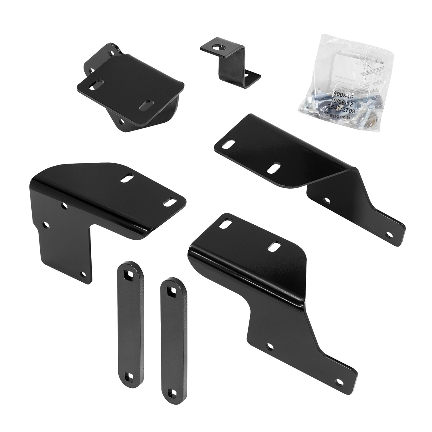
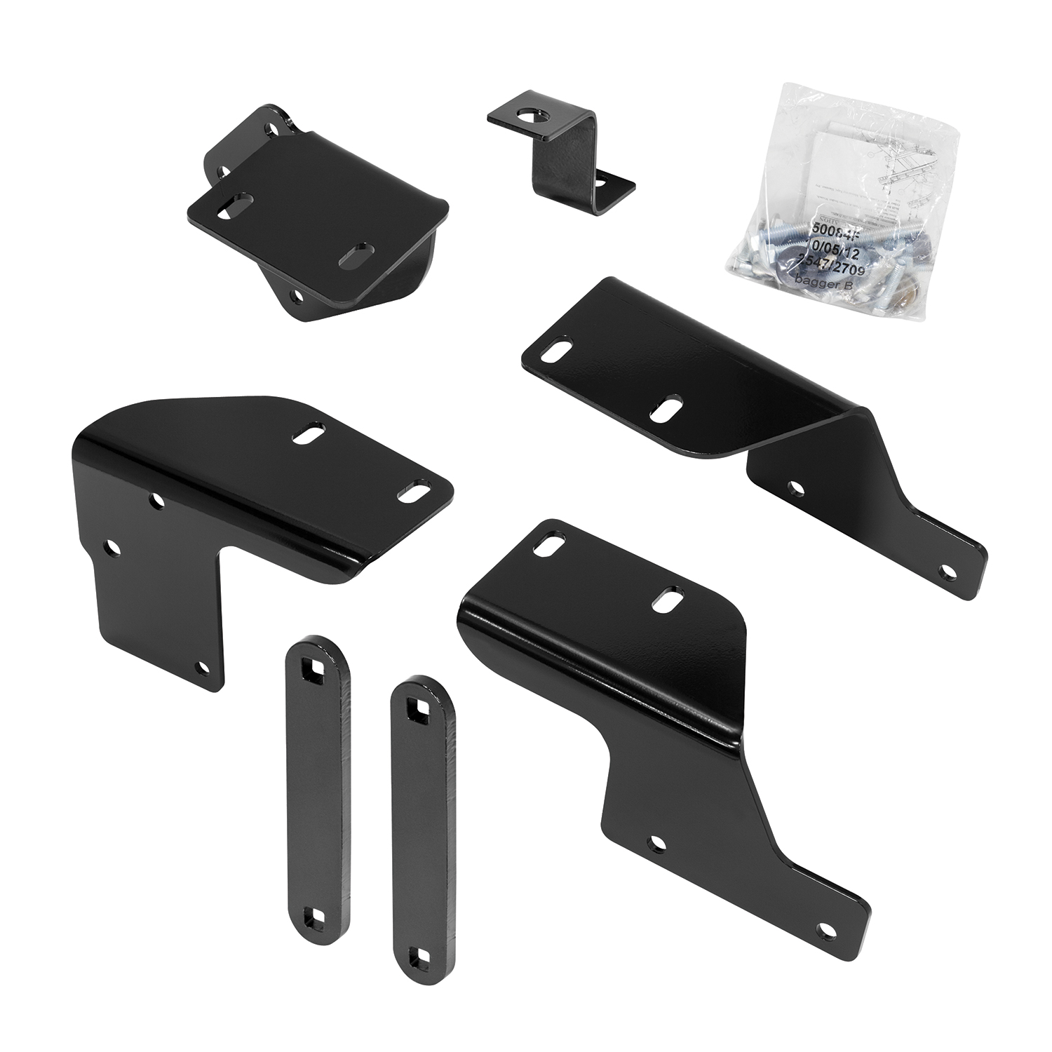
The 50084 is a mounting bracket kit designed to attach 30035 & 58058 fifth-wheel rails to 2007–Current Toyota Tundra trucks. It includes all fasteners needed to secure the custom brackets to the frame. The kit requires drilling into the truck bed and uses Grade 8 bolts, nuts, and washers.
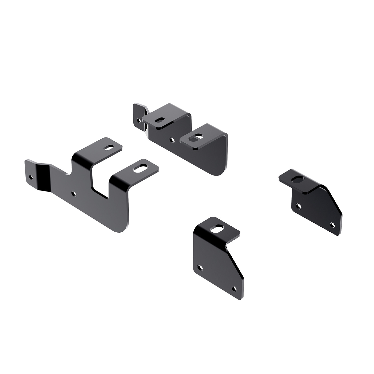
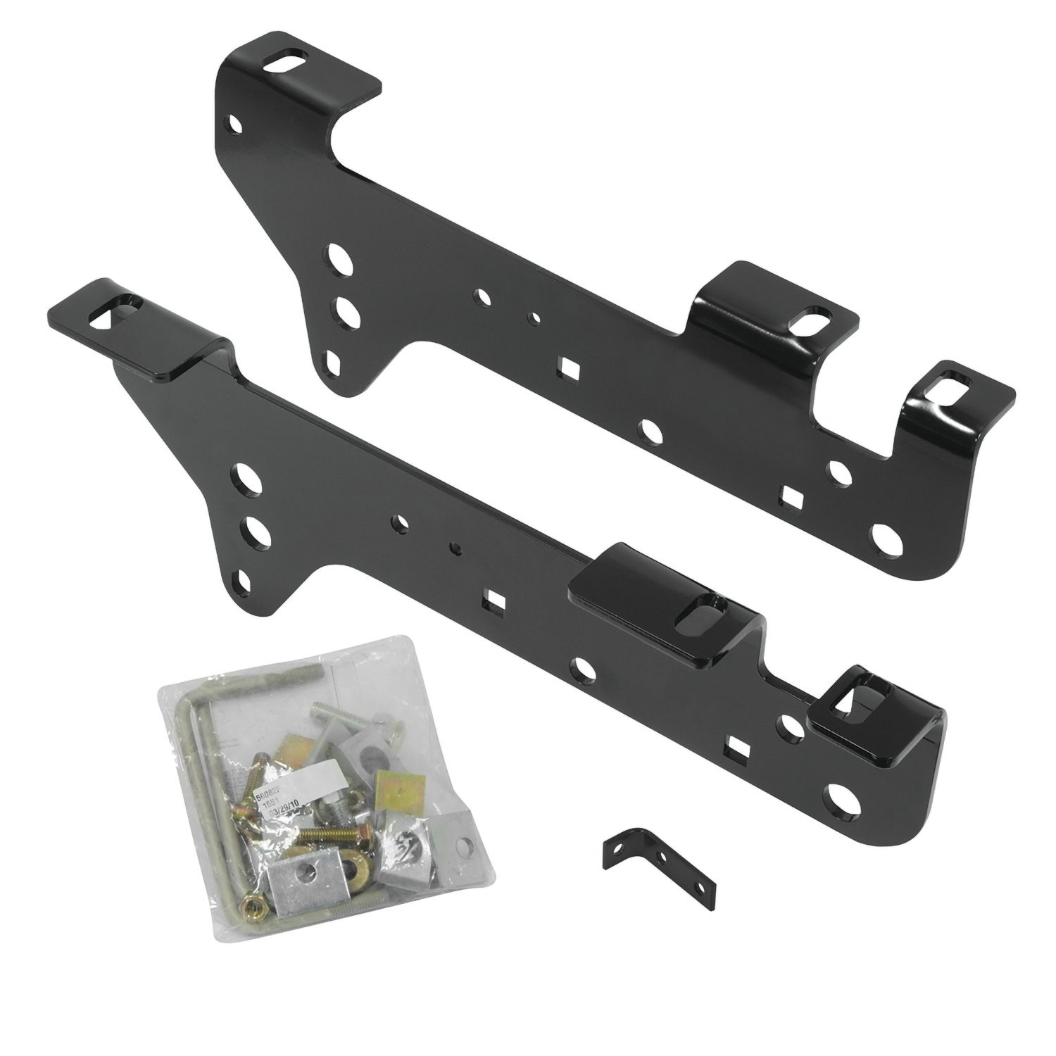
The kit includes: 4× 1/2" conical washers, 2× 5/8" conical washers, 2× 5/8" flat washers, 4× 1/2"-13 × 5.5" Grade 8 carriage bolts, 2× 5/8"-11 × 2" Grade 8 hex bolts, 2× 5/8"-11 Grade 8 hex nuts, 4× 1/2"-13 Grade 8 hex nuts, 1× driver's side front bracket, 1× passenger's side front bracket, 1× driver's side rear bracket, 1× passenger's side rear bracket, 2× strap brackets, 1× S bracket, 4× M14-1.5 × 40 hex bolts, 4× 9/16" lock washers, 2× 1/2"-13 × 2" Grade 5 hex bolts, and 2× 1/2" flat washers. All other fasteners for the rails are supplied separately with parts 30035 & 58058.
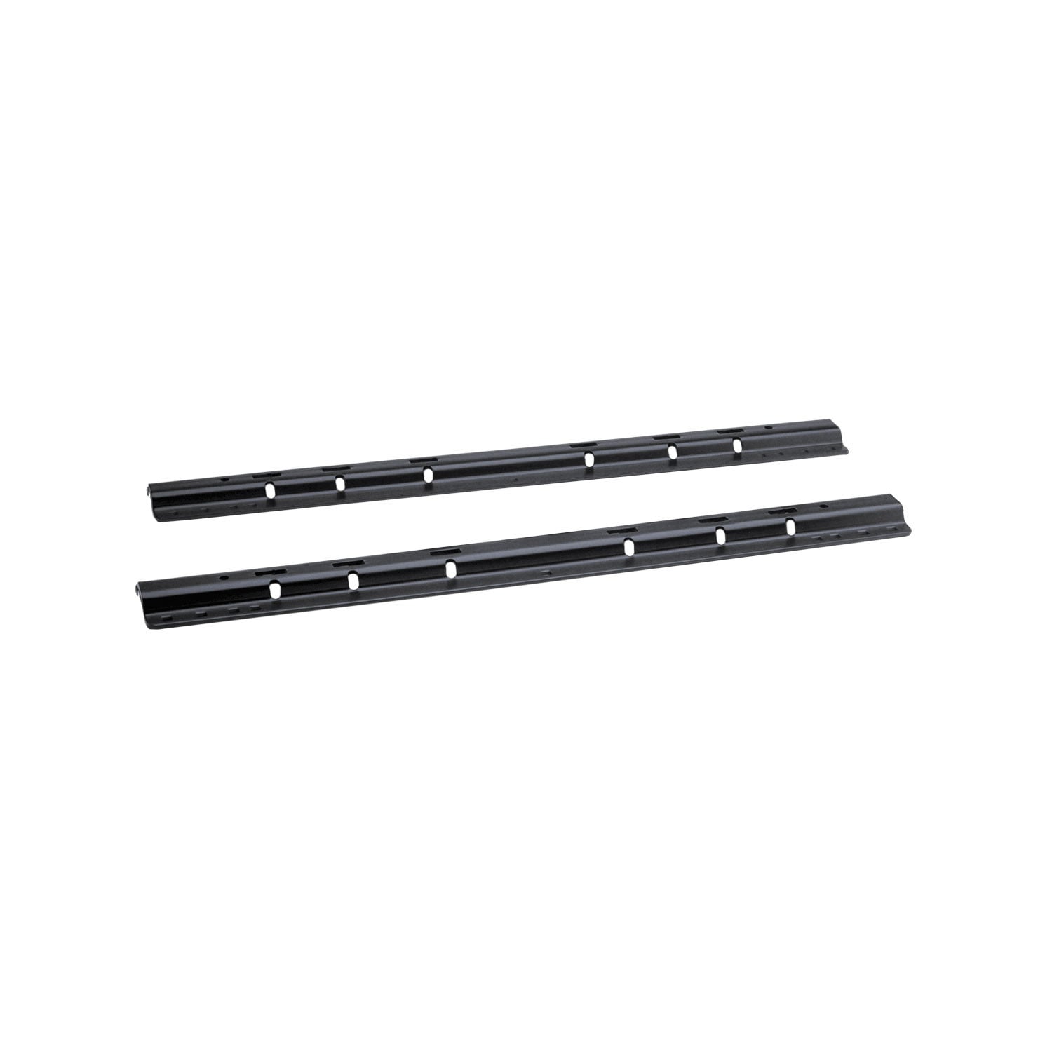
The 50084 is designed for 30035 & 58058 rails only. It will not work with other rail systems.
Not completely. If a bumper/hitch bracket is present, you must remove 5 of the 6 bolts on both sides and loosen the top rear bolt to allow the bracket to pivot down. This creates space for the frame brackets. After installing the rear frame brackets, you rotate the bumper/hitch bracket back to its original position and loosely install the M14 bolts.
For the driver's side front bracket placement, you must remove the nut on the outside of the frame that supports the existing electrical box. The electrical box is then repositioned using the provided S bracket and original frame fasteners to create additional space for the driver's side bracket strap. It is reattached in step 18 after the mounting rails are installed.
Place the rear mounting rail in the truck bed and use a tape measure to center it between the weld seams along the length of the truck bed floor. Position it at the correct distance from the rear edge of the truck as shown in Figure 3. The rail should be centered to ensure proper alignment with the rear frame brackets (10) and (11).
Place the unassembled fifth-wheel legs with cross member/slider/goose into the already-installed rear mounting rail. Position the front mounting rail by inserting the tabs into the mounting rail and pushing it tight toward the rear rail. Ensure the front rail is centered between the weld seams on the truck bed floor. If more than one hitch product will be used with the rails, both should be positioned at the same time to align the second rail and ensure one product does not compromise the fit of the other.
For each of the two front brackets: (1) Insert one 1/2" × 5.5" carriage bolt (item 4) through each square hole on a strap bracket (item 12) so the bolt slides snugly into position. (2) Starting with the front mounting hole on the driver's side, position the strap and bolts on the inside of the frame so the bolts slide through the top and bottom strap holes on the bracket. (3) Install the 1/2" conical washer (item 1) and 1/2" nut (item 7), hand-tighten only. (4) Install the 5/8" × 1.75" bolt (item 5) with flat washer (item 3) through frame brackets (8)(9) and frame, then install the 5/8" conical washer (item 2), S bracket (item 13, driver's side only), and 5/8" nut (item 6), hand-tighten only.
The U-shaped spacer is placed in the corrugation between the truck bed and the mounting rail, or between the bed and the frame bracket. This ensures metal-to-metal contact and prevents crushing the bed corrugation when the 1/2" × 2" carriage bolts are tightened.
The drilling sequence is: (1) Mark and center-punch hole locations per Figure 3. (2) Drill each position with a 1/8" pilot bit. (3) Verify the 1/8" holes align with the slots of the frame brackets. (4) Enlarge the 1/8" holes to 9/16". This two-step drilling process is performed for both the rear mounting rail (steps 6–8) and the front mounting rail (steps 12–14). Always protect fuel tank, filler tubes, brake lines, and wire harness on the driver's side by placing metal between the bed floor and these components before drilling.
When drilling, especially on the driver's side, place a piece of metal between the truck bed floor and potential components at risk to protect the fuel tank, filler tubes, brake lines, and wire harness from being drilled into. The manual emphasizes this warning multiple times during the drilling steps.
All 1/2" hardware must be torqued to 75 ft·lb. This includes the 1/2"-13 carriage bolts and 1/2"-13 hex nuts.
All 5/8" hardware must be torqued to 212 ft·lb. This includes the 5/8"-11 hex bolts and 5/8"-11 hex nuts.
All M14 hardware must be torqued to 122 ft·lb. This applies to the M14-1.5 × 40 hex bolts used to attach the rear frame brackets.
Final torque is applied in step 20, after all bolts have been hand-tightened and the mounting rails and brackets are positioned. The manual specifies hand-tightening only during the bracket and rail installation steps (steps 10, 15, 17), then final torque is applied once everything is in place.
During installation, bolts are hand-tightened only until the mounting rails and brackets are positioned. Specifically, in steps 10, 15, and 17, the manual instructs to "hand tighten only" or "tighten snug to keep the mounting rail from moving." Final torque specifications are applied only in step 20, after all components are in their final positions.
Always measure your truck and trailer before installing the hitch to ensure there is clearance at the cab and at the bumper to allow for turns. This prevents interference during turning and ensures safe towing.
Owner responsibilities include: (1) Refer to vehicle tow rating for correct weight capacity. (2) Refer to mounting bracket rating label for correct weight capacity. (3) Check mounting system bolt tightness once per year. (4) Save warranty sheet and receipt for any future support.
No. The manual explicitly states: "Use only bolts, nuts, and washers supplied to install this kit. All bolts and nuts are Grade 8 unless otherwise specified." Using non-supplied fasteners may compromise the installation and void the warranty.
The manual states that "all other mentioned fasteners are supplied with part number 30035 & 58058." The 50084 kit includes only the hardware needed to attach the custom brackets to the frame. Refer to the 30035 or 58058 rail kit documentation for the complete list of fasteners supplied with those products.
The installation sequence is: (1) Remove spare tire and wheel well liners if needed. (2) Reposition the electrical box using the S bracket. (3) Remove and pivot the bumper/hitch bracket if present. (4) Install rear frame brackets (10) & (11). (5) Position and drill the rear mounting rail. (6) Install rear mounting rail with carriage bolts and spacers. (7) Position the front mounting rail with fifth-wheel legs. (8) Drill the front mounting rail. (9) Install front brackets (8) & (9) and strap brackets (12). (10) Install front mounting rail with carriage bolts and spacers. (11) Reattach electrical box and bumper/hitch bolts. (12) Apply final torque to all fasteners.
The front and rear rails must be centered between the weld seams on the truck bed floor. When positioning the front rail, insert its tabs into the rear rail and push it tight toward the rear rail. If more than one hitch product will be used with the rails, both should be positioned at the same time to align the second rail and ensure one product does not compromise the fit of the other.
The manual states: "If more than one hitch product will be used with the rails then both should be used at the same time to align the second rail. This will ensure that one product does not compromise the fit of the other." This suggests multiple products can be used, but they must be positioned simultaneously during installation.
The center punch is used to mark the exact hole locations on the truck bed before drilling. After positioning the mounting rail and identifying the hole locations per Figure 3, you mark and center-punch each position to ensure accurate drilling.
Figure 3 shows the critical dimensions: the mounting rail must be positioned 27 9/16" from the front of the vehicle (measured to the center line of the hitch), and approximately 1 3/4" from the rear edge of the truck bed. The rail must be centered between the weld seams on the truck bed floor. These dimensions ensure proper alignment with the fifth-wheel coupling and frame brackets.
The 50084 includes a Limited Lifetime Warranty from Cequent Performance Products, Inc. The warranty covers material defects in both material and workmanship, ordinary wear and tear excepted, provided installation and use comply with product instructions. The warranty is limited to the original consumer purchaser only and is not transferable. It does not cover normal wear and tear, damage from abuse, misuse, misapplication, overloading, improper installation, improper maintenance, or unauthorized alterations. Product replacement is the sole remedy; the manufacturer is not liable for service or labor charges.
To file a warranty claim, contact Cequent Performance Products, Inc. at 47912 Halyard Dr. Suite 100, Plymouth, MI 48170, or call 1-888-521-0510. Identify the product by model number (50084) and follow the claim instructions provided. You must provide the product and purchase receipt to process the claim. You are responsible for return shipping costs. Retain your purchase receipt to verify the date of purchase and that you are the original consumer purchaser.
Stop and reposition the mounting rail. The manual instructs you to check alignment in steps 7 and 13: "Check that the 1/8 inch drilled holes align with the slots of the rear frames brackets (10) and (11)" and "Check that the 1/8 inch drilled holes align with the slots of the front frames brackets (8)." If alignment is incorrect, move the rail out of the way, fill or ignore the misaligned pilot holes, and reposition the rail before drilling the final 9/16" holes.
The carriage bolts and spacers may not be tightened sufficiently. The manual instructs to "tighten snug to keep the mounting rail from moving" in steps 10 and 17. Ensure the U-shaped spacer is properly positioned in the bed corrugation to provide metal-to-metal contact, and tighten the 1/2" × 2" carriage bolts with washers and hex nuts until the rail is secure but not yet at final torque.
Stop immediately and do not proceed with installation. The manual provides a specific warning: "When installing to Figure 1 & 3, during drilling protect the fuel tank and filler tubes, brake lines and wire harness by placing a piece of metal between the box floor and potential components at risk on the driver's side." If damage has occurred, contact a qualified technician or the vehicle manufacturer for repair assessment before continuing.
The manual warns: "Be careful when rotating bumper/hitch bracket not to damage vehicle." Ensure you have loosened the top rear bolt sufficiently in step 3 to allow smooth pivoting. Rotate slowly and carefully, and do not force the bracket. If damage has occurred, stop and assess the damage before proceeding.
The U-shaped spacer is not properly positioned or is missing. The manual states: "Install the 1/2" x 2" carriage bolts with the U-shaped spacer to be located in the corrugation between the box and the mounting rail or between box and frame bracket (10) & (11). This insures a metal to metal contact and to prevent crushing the bed corrugation." Loosen the bolts, reposition the spacer in the corrugation, and retighten.
Remove the inner plastic wheel well covers. The manual states in step 1: "If equipped with inner plastic wheel well liner, remove inner plastic wheel well covers to allow access to frame."
No. The manual explicitly states: "Do not install mounting rails over plastic bed liners. Plastic bed liners must be cut out of the way to provide metal to metal contact." You must cut away the plastic bed liner in the areas where the mounting rails will be installed. Spray-in liners are acceptable and do not need to be removed.
Jennifer
Ordered online. Shipment arrived on time and with all the correct parts. Great customer service and friendly staff. Also, pricing was great!
May 22, 2023
On Sale Today
Original price was $301.25. Current price is $230.55.You save $70.70 (23%)
Free Shipping
Ships free on all orders
 Authorized Dealer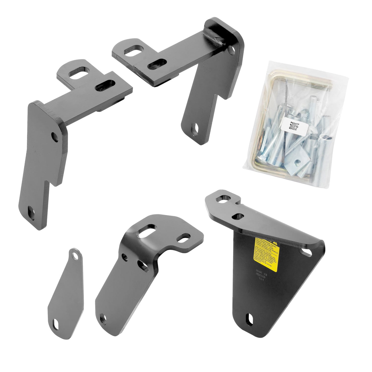

Quick Ship
In stock and ready to ship — order now!
FREE ShippingFREE SHIPPING
Estimated delivery Tue, Oct 13 - Fri, Oct 16
Order before 2 PM EST Monday–Friday for same-day processing
Guaranteed safe & secure checkout
Total for 2 items:
$436.99$517.50