
Air Lift WirelessOne with EZ Mount. 25980EZAir LiftOriginal price was $984.99. Current price is $713.99.In Stock
View productOur in-house experts typically reply within one business day.

Air Lift



Always the correct part
We know our products
Quality Products
Free Shipping!
Always the correct part
We know our products
Quality Products
Free Shipping!
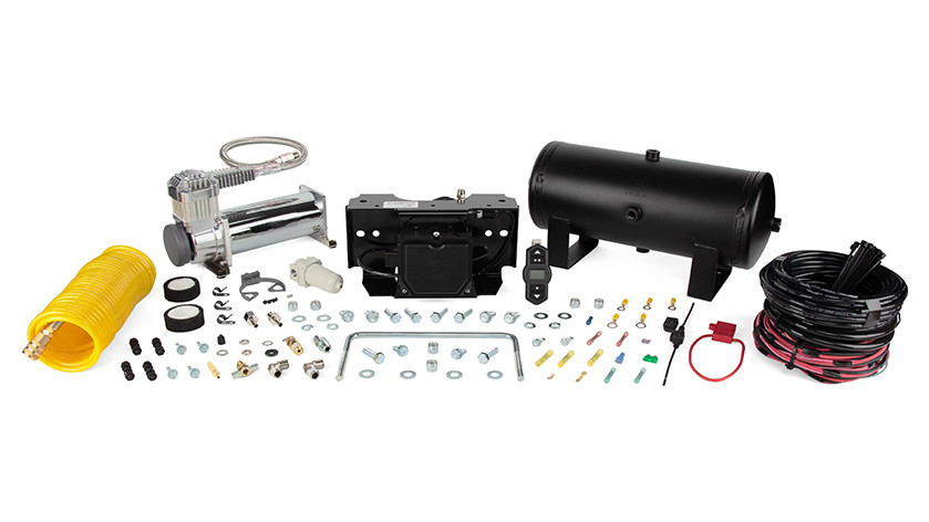
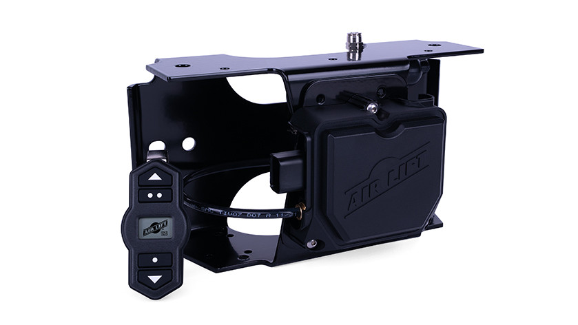
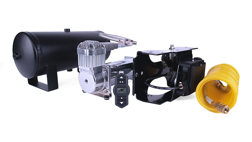
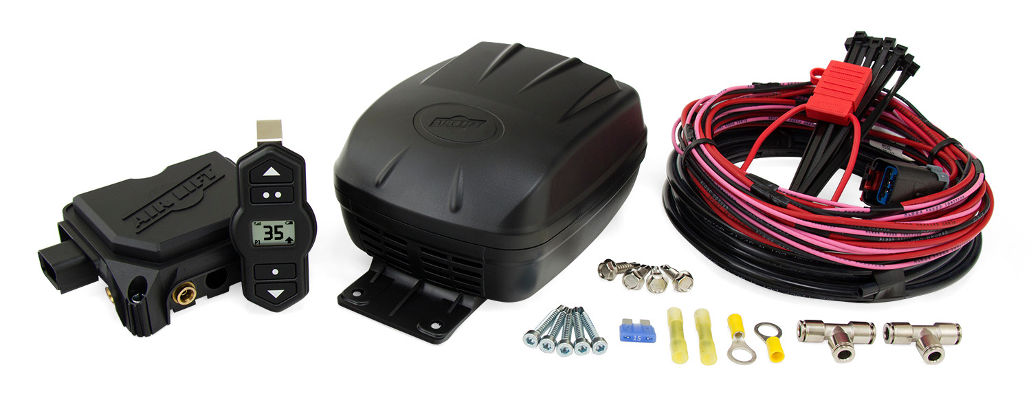
The WirelessOne Tank + EZ Mount by Air Lift integrates a manifold and compressor into a single tank system, equipped with the necessary wiring harness and accessories to enable real-time monitoring and inflation/deflation of air springs.

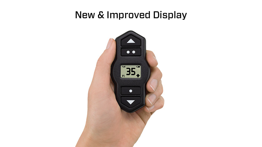
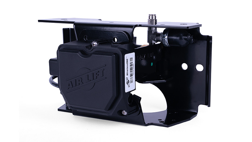
Never stop during a long road trip, searching for an air compressor again. Fine-tune and easily monitor your air spring’s pressure with Air Lift’s WirelessOne Tank + EZ Mount. This kit is an all-in-one solution combining a manifold and compressor into a tank system, with everything needed for seamless connection to your vehicle's power source and air springs of any brand. Adjusting the air pressure can be inconvenient without an air compressor – trying to find a gas station with an air compressor, then fiddle with Schrader valves until the pressures are equalized. Air Lift looked to eliminate that hassle with WirelessOne, making every part of the process simple. The WirelessOne features a 2-gallon powder-coated reserve tank, and its single-path system inflates or deflates air springs to the same pressure. This is ideal for vehicles carrying loads that are equally distributed left-to-right. A mobile app for iOS and Android devices is available on top of the included wireless controller, allowing you to connect to the manifold easily. In addition, the controller and app are programmable with user-defined presets so WirelessOne can remember your frequently used pressures. WirelessOne Tank + EZ Mount packages the manifold and solenoid assembly into one convenient, pre-assembled, and factory-tested EZ Mount bracket. The kit also features a remote mount Shrader valve and a coiled hose with quick connect to run accessories such as filling tires, inflatables or running small air tools. For over 70 years, Air Lift has been the leader in air suspension products and is committed to delivering quality parts that last. To ensure the highest quality, longevity, and customer satisfaction, the system comes with a two-year warranty and a 60-day, no-questions-asked, money-back guarantee – not to mention Air Lift's reputation for excellent customer service and technical support, should you run into any snags in the installation process.
Air Lift Company has developed dependable air spring suspension products since our inception in 1949. Our original product, a rubber air spring inserted into a car’s factory coil spring, was created and patented in 1950. We’ve come a long way since 1949 and are proud to be a dedicated suspension specialist company.
Today, Air Lift load support products are sold worldwide and are engineered to fit over 540 vehicles. Our extensive product line offers air helper springs for trucks, RVs, SUVs, CUVs, and vans, as well as the most technologically advanced on-board air compressor systems for on-the-go air spring control.
Air Lift leads the industry in no-drill applications – kits that bolt onto your vehicle’s frame, speeding the installation process. Our teams work constantly to bring innovative products to you and upgrade existing products with the latest technology.
All of our efforts are spent ensuring your safety and comfort by designing, engineering, and manufacturing the highest quality suspension products. We are a family-owned business based in Lansing, Michigan, and make your family and cargo’s safety our top priority.
Experts available to answer your questions
Call 888-634-94942 Years Limited
The kit includes a 2-gallon air tank (11175), 444C chrome compressor (16444), WirelessONE tank harness (26933), tire fill air line coiled (22043), 1/4" air line 30 feet (20230), and multiple hardware packs containing fittings, fasteners, electrical connectors, fuses, and zip ties. The EZ Mount version (25981EZ) additionally includes the EZ Mount assembly (26570) and Wireless One key fob (72719). The upgrade version (25981) includes a stand-alone filter bracket assembly with pressure switch and solenoid valve.
Air Lift Company provides a 2-year Limited Warranty to the original purchaser from the date of original purchase. The warranty covers defects in workmanship and materials when the product is used on cars and trucks as specified by Air Lift Company and under normal operating conditions. Full warranty terms, requirements and exclusions are available at www.airliftcompany.com/warranty. To register your warranty, visit https://www.airliftcompany.com/support/warranty/register/
The system is designed for cars and trucks as specified by Air Lift Company. The manual states it is for vehicles equipped with Standalone Kit 25980 or EZ Mount Kit 25980EZ. However, the manual does not provide specific vehicle year, make, model, bed length, cab style, drivetrain or frame type compatibility information. Contact Air Lift customer service at (800) 248-0892 for specific fitment details for your vehicle.
The manual states that if you purchased the upgrade kit, the compressor, wiring harness and electrical connections currently on your vehicle will NOT be used and will have to be removed before installation can begin. However, the manual does not specify whether the system is compatible with factory air suspension components or sensors. Contact Air Lift customer service at (800) 248-0892 for compatibility information with your vehicle's existing suspension system.
Yes. The manual states: "DISCONNECT THE BATTERY GROUND BEFORE INSTALLING THE SYSTEM." Additionally, the manual warns: "REMOVE ALL FUSES WHEN JUMP-STARTING OR WELDING ON THE VEHICLE. FAILURE TO DO SO COULD DAMAGE THE MANIFOLD."
Required tools include: power drill, 1/4" and 3/8" drill bits, grinder, standard wrench set, 3/8", 1/2", 5/16" and 9/16" sockets with ratchet, 3/32" hex key, wire stripping/crimping tool, sharp razor knife, lighter or torch, and Teflon tape. The manual also recommends having rubber grommets (not supplied) for routing air lines and wiring through frame holes.
The manual recommends mounting the tank system in the middle of the vehicle to optimize wireless performance. Components should be kept at least 6 inches away from heat sources such as the exhaust. Air lines and wiring should be routed away from sharp edges and supported every 8-12 inches (200-300mm) with zip ties. The manifold assembly can be no longer than approximately 6 feet from the tank assembly based on wiring length. Layout the system before drilling to ensure all necessary wiring connections can be made. See Figure 1 in the manual for a suggested component layout example.
Before drilling any holes, you must ensure the back side of the frame rail is clear of vehicle components, including brake lines, fuel lines, wiring, and other components. The manual emphasizes this with a CAUTION: "BEFORE DRILLING, ENSURE THE BACK SIDE OF THE FRAME RAIL IS CLEAR OF VEHICLE COMPONENTS, INCLUDING BRAKE LINES, FUEL LINES, WIRING, ETC." This check is required before drilling for the compressor, tank, EZ Mount bracket, and solenoid bracket.
Yes, drilling is required. The system requires drilling holes for mounting the compressor, tank, EZ Mount bracket, and solenoid bracket (on upgrade systems). The manual provides drilling templates for the compressor (16444), EZ Mount assembly (26570), and air tank (11175). Drill bit sizes used include 1/4" for pilot holes and 3/8" for through-bolt holes. The manual emphasizes that drilling templates must be printed at 100% scale to ensure accurate hole placement.
The compressor drilling template shows a hole pattern with dimensions of 8 1/2" and 3 5/16". The manual instructs to center-punch and drill four holes using the compressor or the drilling template (Figure 20), then secure the compressor using the supplied hardware. Use a 1/4" drill bit to make pilot holes if using self-tapping screws, or a 3/8" drill bit if using through bolts.
The EZ Mount assembly has two drilling templates (Figures 21 and 22) for the top flange and web. The top flange template shows 8 3/16" (actual 8.20", 208.3mm). The web template shows dimensions of 5 9/16" (actual 5.55", 141mm), 7" (actual 7.00", 177.8mm), and 10 5/8" (actual 10.62", 269.7mm). IMPORTANT: The template must be printed at 100% scale before use. Use the provided 1-inch or 1cm scale verification marks to confirm correct printing. Use a 1/4" drill bit for pilot holes if using self-tapping screws.
The air tank drilling template (Figure 23) shows dimensions of 9.50 and 4.25. The manual provides this template for mounting the 2-gallon tank. Use a 1/4" drill bit to make pilot holes if using self-tapping screws, or a 3/8" drill bit if using through bolts with hex cap screws.
No. The manual explicitly states: "Do not use scissors or wire cutters because these tools will deform the air line." Use a sharp knife or hose cutter and make clean, square cuts. Do not cut the lines at an angle. Inspect the air line for scratches that run lengthwise after cutting. If the air line is damaged, contact Air Lift customer service. The minimum bend radius for 1/4" air line is 1" (25mm).
If using hex cap screws (part N), flat washers (M), lock washers (P) and lock nuts (L) for tank mounting, torque to 21-25 lb.-ft. (30-34 Nm). If using self-threading screws (part O), no torque specification is provided because there are too many variables. Use a 1/4" drill bit for pilot holes with self-threading screws, or a 3/8" drill bit for through bolts.
The torque specifications for EZ Mount mounting depend on the fastener type: Hex cap bolts (3B) with flat washers (5B) and nylon lock nuts (4B): 21-25 lb.-ft. (30-34 Nm). U-bolt (2B) with washers (5B) and nylon lock nuts (4B): 4-6 lb.-ft. (5.4-8.1 Nm). Self-tapping screws (6B): No torque specification is provided because there are too many variables. Do not hang EZ Mount from a horizontal surface using self-tapping screws.
The hex screws mounting the solenoid valve bracket assembly should be torqued to 23 in.-lbs. The manual states: "Torque the screws to 23 in.-lbs." This applies when repositioning the solenoid/filter bracket for horizontal orientation of the EZ Mount bracket. Use a 3/32" hex wrench and ensure it is fully seated to avoid stripping the screw head.
The filter assembly should be mounted to the bracket (7A) using a serrated hex cap screw (10A), split lock washer (9A) and flat washer (8A) torqued to 18-24 in.-lbs. This applies to upgrade systems only when assembling the remote mount filter/pressure switch/solenoid assembly.
When reassembling the bracket and manifold to the EZ Mount bracket during horizontal orientation setup, torque the three screws to 23 in.-lbs. The manual states: "Re-assemble the bracket and manifold to the EZ Mount bracket (as shown in Fig. 4) with the previously removed (3) screws. Torque the screws to 23 in.-lbs."
The kit includes two fuses: a 30A spade fuse (24547, part T) and a 3A ATM fuse (24503, part U). The 30A fuse is installed in the ATC fuse holder (24500, part R) for the battery power connection. The 3A fuse is installed in the HHL fuse holder (24501, part S) for the keyed power/ignition connection. Do not install the fuses until all connections are complete.
The main harness (26933) uses the following wire colors: red for battery power, black for ground, and pink for ignition wire. The solenoid valve has red wires, the pressure switch has black wires, and the compressor has black and red/white wires. The manual specifies connecting black to black and red to red/white on the compressor connections.
The pressure switch (11A) has two black wires. Crimp a blue butt connector (X) to one of the black wires and apply heat to seal it. To the other black wire on the pressure switch, crimp a yellow ring terminal (W) to the end. This ring terminal must attach to the vehicle frame using a self-tapping screw (Q) and must have a good ground connection to the frame. It may be necessary to grind some paint or rust off the frame to make a good connection.
Cut off the terminals on the compressor (A) before attaching to the main harness. Crimp yellow butt connectors (V) between the compressor and the main harness compressor wires, connecting black to black and red to red/white. Apply heat to the butt connectors to seal them. The manual specifies using 12-10 gauge shrink tube butt connectors (24752, part V) for this connection.
Crimp red butt connectors (DD) between the solenoid valve and the main harness wires labeled solenoid valve. Apply heat to the butt connectors to seal them. The manual specifies using 18-22 gauge center butt connectors (24680, part DD) for this connection.
For the battery power connection: Crimp a yellow butt connector (V) to the red power wire on the main harness. Crimp the other end to the red ATC fuse holder (R) after cutting the wire to split into two equal halves. Apply heat to seal. Crimp a yellow 3/8" (CC) or 1/4" (W) ring terminal to the other side of the red wire on the ATC fuse holder and attach to the positive battery post. For ground: Crimp a yellow 3/8" (CC) or 1/4" (W) ring terminal to the black ground wire on the main harness and attach to the ground battery post. Do not install the fuse at this time.
Crimp a blue butt connector (X) to the pink ignition wire on the main harness. Crimp the other end to one of the ends of the black mini fuse holder (S). Apply heat to seal. Determine the correct fuse adapter type for your vehicle's fuse box: Adapter #1 (BB) for standard ATC type fuses, or Adapter #2 (AA) for smaller mini-type fuses used in late-model vehicles. Install the 3A fuse into the adapter, then install the fuse back into the fuse box. Connect the end of the fuse holder with the female push-on connector (Y or Z) onto the adapter.
The manifold assembly can be no longer than approximately 6 feet (6') from the tank assembly based on wiring length. The manual states: "The manifold assembly can be no longer than 6' (6 feet) from the tank assembly based on wiring." Do not extend electrical wiring, as this could result in system function issues.
Key safety precautions include: (1) Disconnect the battery ground before installing the system. (2) Remove all fuses when jump-starting or welding on the vehicle to prevent manifold damage. (3) Ensure the back side of the frame rail is clear of brake lines, fuel lines, and wiring before drilling. (4) Do not extend electrical wiring. (5) Keep components at least 6 inches away from heat sources such as exhaust. (6) Route air lines and wiring away from sharp edges. (7) Do not back out fittings after installation as this could cause leaks. (8) Make clean, square cuts on air lines; do not use scissors or wire cutters. (9) Do not mount EZ Mount with electrical connector or Air Lift logo pointed down.
Tanks act as accumulators and will accumulate water from moisture. The manual states: "TANKS ACT AS ACCUMULATORS AND WILL ACCUMULATE WATER FROM MOISTURE. IT WILL BE IMPORTANT TO PERIODICALLY DRAIN THE TANK USING THE DRAIN COCK; OTHERWISE, YOU COULD DAMAGE OTHER COMPONENTS IN THE SYSTEM." The drain cock (II) should be installed into the tank port that points to the ground. Similarly, the filter will collect water and needs to be manually drained periodically to prevent damage to other components.
The EZ Mount assembly (26570) can be mounted in any orientation EXCEPT: (1) with the electrical connector pointed down, or (2) with the Air Lift logo facing the ground. The manual states: "EZ Mount can be mounted in any orientation except with the electrical connector pointed down or with the Air Lift logo facing the ground (Fig. 11)." Additionally, do not hang EZ Mount from a horizontal surface using self-tapping screws.
The minimum bend radius for 1/4" air line is 1 inch (25mm). The manual states: "The minimum bend radius for the air line is 1" (25mm)." When routing air lines, avoid sharp edges and allow for proper bend radius to avoid kinking. Leave at least 2 inches (50mm) of slack in the air line to allow for any movement that might pull on the air line.
After installation, ensure: (1) All electrical connections are secure and properly crimped with heat-sealed butt connectors. (2) The manifold connector is fully seated on the manifold with an audible click. (3) The pressure switch has a good ground connection to the vehicle frame. (4) All air line connections are tight and secure. (5) Air lines are routed away from sharp edges and heat sources. (6) The EZ Mount bracket is properly oriented (not with connector or logo pointing down). (7) All fasteners are torqued to specification. (8) Do not install fuses until all connections are complete. (9) Refer to the User Guide for mobile app/controller pairing instructions.
The manual specifies two key maintenance tasks: (1) Periodically drain the tank using the drain cock (II) to remove accumulated water from moisture. Tanks act as accumulators and will accumulate water, which could damage other components if not drained. (2) Periodically drain the filter (HH) to remove accumulated water. The filter will collect water and needs manual draining to prevent damage to other components. The manual does not provide specific drain intervals; contact Air Lift customer service at (800) 248-0892 for recommended maintenance schedules.
For details on operating the system, connecting the wireless controller, and connecting your mobile device to the system, refer to the WirelessONE User Guide (AD-946) included with your kit. The manual also references video-enhanced installation guides available at airliftcompany.com/workshop/category/install-videos (subject to availability). For specific operation questions, contact Air Lift customer service at (800) 248-0892.
The system is designed for cars and trucks as specified by Air Lift Company and vehicles equipped with Standalone Kit 25980 or EZ Mount Kit 25980EZ. For specific fitment details for your vehicle year, make, and model, contact Air Lift customer service at (800) 248-0892.
Required tools: power drill, 1/4" and 3/8" drill bits, grinder, wrench set, 3/8", 1/2", 5/16" and 9/16" sockets with ratchet, 3/32" hex key, wire stripping/crimping tool, sharp razor knife, lighter or torch, and Teflon tape. Rubber grommets (not supplied) are recommended for routing air lines through frame holes.
Tank mounting (hex cap screws): 21-25 lb.-ft. (30-34 Nm). EZ Mount hex cap bolts: 21-25 lb.-ft. (30-34 Nm). EZ Mount U-bolt: 4-6 lb.-ft. (5.4-8.1 Nm). Solenoid bracket hex screws: 23 in.-lbs. Filter assembly bracket: 18-24 in.-lbs. Manifold assembly screws: 23 in.-lbs. Self-tapping screws have no torque specification due to variables.
The kit includes a 30A spade fuse for the battery power connection (ATC fuse holder) and a 3A ATM fuse for the keyed ignition connection (HHL fuse holder). Do not install fuses until all connections are complete. Remove all fuses when jump-starting or welding on the vehicle.
Yes. The manual states: "DISCONNECT THE BATTERY GROUND BEFORE INSTALLING THE SYSTEM." Also remove all fuses when jump-starting or welding on the vehicle to prevent manifold damage.
Periodically drain the tank using the drain cock to remove accumulated water from moisture. Also periodically drain the filter to remove accumulated water. Failure to drain could damage other components. Contact Air Lift customer service at (800) 248-0892 for recommended drain intervals.
Mount in the middle of the vehicle to optimize wireless performance. Keep all components at least 6 inches away from heat sources like exhaust. The manifold assembly can be no longer than 6 feet from the tank assembly. Support wiring and air lines every 8-12 inches with zip ties.
Inspect the air line for scratches that run lengthwise after cutting. If the air line is damaged, contact Air Lift customer service at (800) 248-0892. Do not use damaged air lines as they may cause leaks or system failure. To prevent damage, use a sharp knife or hose cutter and make clean, square cuts. Do not use scissors or wire cutters, as these tools will deform the air line.
If the pressure switch does not have a good ground connection to the vehicle frame, it may be necessary to grind some paint or rust off the frame to make a good connection. The yellow ring terminal (W) from the pressure switch's second black wire must attach to the vehicle frame using a self-tapping screw (Q). Ensure the connection point on the frame is clean and bare metal for proper grounding. A poor ground connection may cause system function issues.
The manifold connector should produce an audible click when properly attached to the manifold. If you do not hear a click, the connector may not be fully seated. Disconnect and reattach the connector, ensuring it is fully inserted until you hear the audible click. If the connector still does not click or does not stay connected, contact Air Lift customer service at (800) 248-0892 for technical assistance.
The minimum bend radius for 1/4" air line is 1 inch (25mm). If the air line is kinked or bent too sharply, it may restrict air flow or cause damage. When routing air lines, avoid sharp edges and allow for proper bend radius. Leave at least 2 inches (50mm) of slack in the air line to allow for any movement that might pull on the air line. If an air line is damaged, contact Air Lift customer service at (800) 248-0892.
The manual states: "NEVER BACK OUT A FITTING AFTER IT IS INSTALLED BECAUSE IT COULD CAUSE A LEAK." If you have backed out a fitting, it may cause a leak in the system. Remove the fitting completely and reinstall it fresh, applying tape or pipe dope as specified in the installation instructions. Install 1 1/2-2 turns beyond finger-tight. If a leak develops, contact Air Lift customer service at (800) 248-0892.
The EZ Mount assembly can be mounted in any orientation EXCEPT with the electrical connector pointed down or with the Air Lift logo facing the ground. If the bracket is mounted in an unacceptable orientation, it must be remounted. Disconnect the wiring harness and fasteners, reposition the bracket so the connector and logo are not pointing down, and reinstall. Refer to Figure 11 in the manual for examples of unacceptable mounting orientations.
The drilling templates must be printed at 100% scale to ensure accurate hole placement. Before using a template, verify the scale using the provided 1-inch or 1cm scale verification marks. Measure the printed scale with a measuring tool to confirm it measures exactly 1 inch or 1 centimeter. If the template is not printed at 100% scale, reprint it at the correct scale. Using an incorrect template to drill holes may cause damage to the vehicle. The manual states: "USING AN INCORRECT TEMPLATE TO DRILL HOLES MAY CAUSE DAMAGE TO THE VEHICLE!"
When removing the hex screws from the solenoid valve bracket/assembly, use a 3/32" hex wrench and ensure it is fully seated to avoid stripping the screw head. The manual states: "MAKE SURE THE HEX WRENCH IS FULLY SEATED SO AS NOT TO STRIP THE HEAD OF THE SCREW SINCE IT WILL BE USED ON THE RE-ASSEMBLY PROCESS." If a screw head is stripped, contact Air Lift customer service at (800) 248-0892 for a replacement screw.
On Sale Today
Original price was $1,842.99. Current price is $1,335.99.You save $507.00 (28%)
Free Shipping
Ships free on all orders
 Authorized Dealer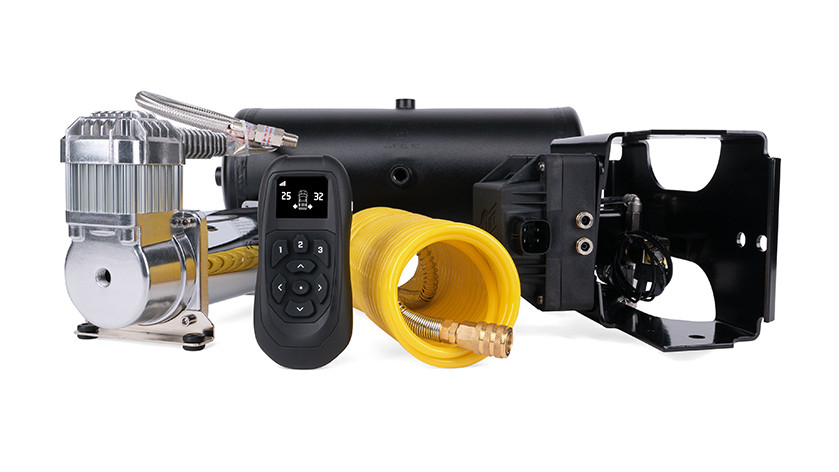

Quick Ship
In stock and ready to ship — order now!
FREE ShippingFREE SHIPPING
Estimated delivery Thu, Oct 22 - Sun, Oct 25
Order before 2 PM EST Monday–Friday for same-day processing
Guaranteed safe & secure checkout
No reviews have been added for this product.
