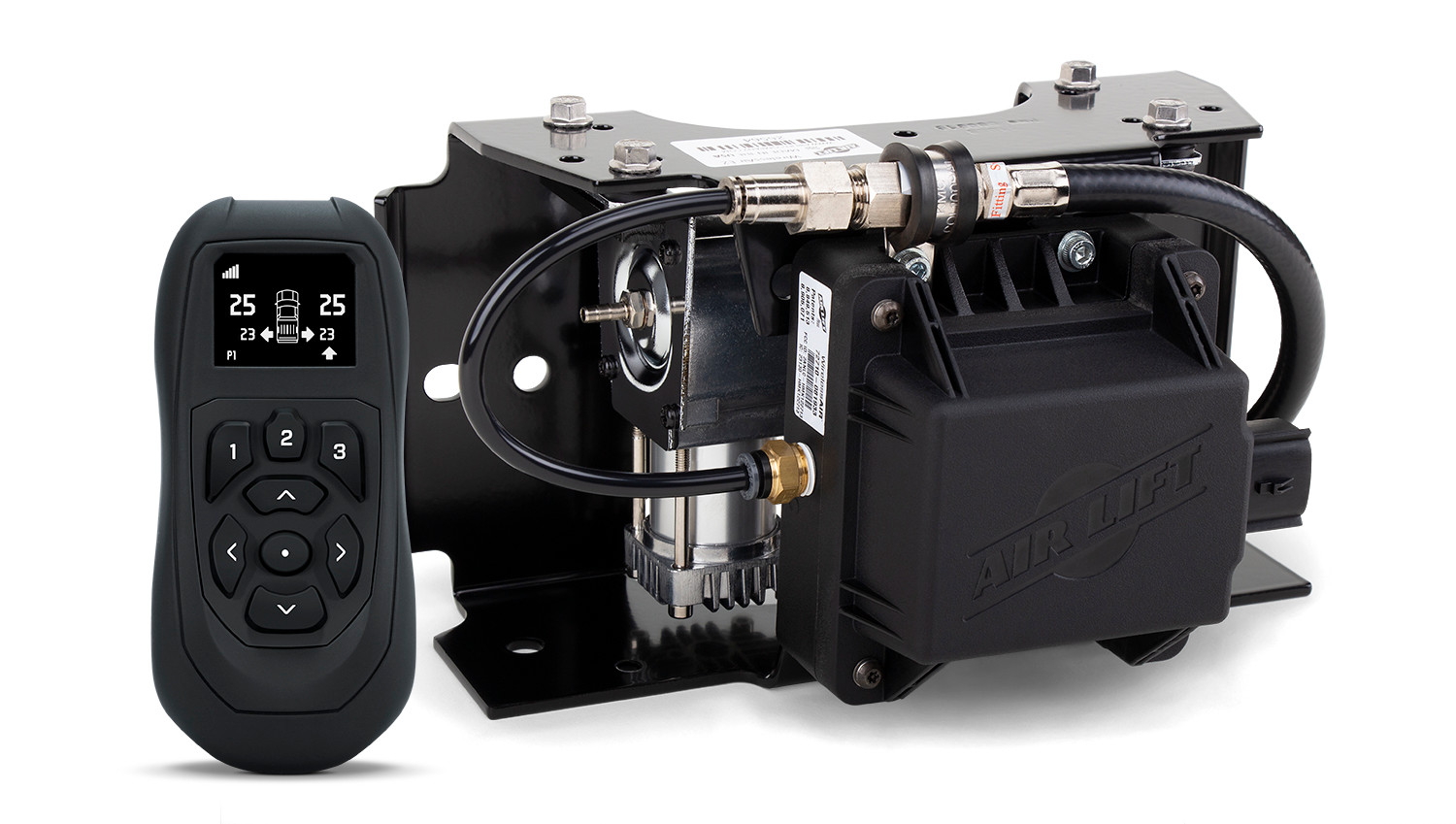
Air Lift EZ Mount WirelessAIR (2nd Generation) 74000EZAir LiftOriginal price was $1,291.99. Current price is $936.99.In Stock
View productOur in-house experts typically reply within one business day.

Air Lift
On Sale Today
Original price was $1,881.99. Current price is $1,515.95.You save $366.04 (19%)
Free Shipping
Ships free on all orders
 Authorized Dealer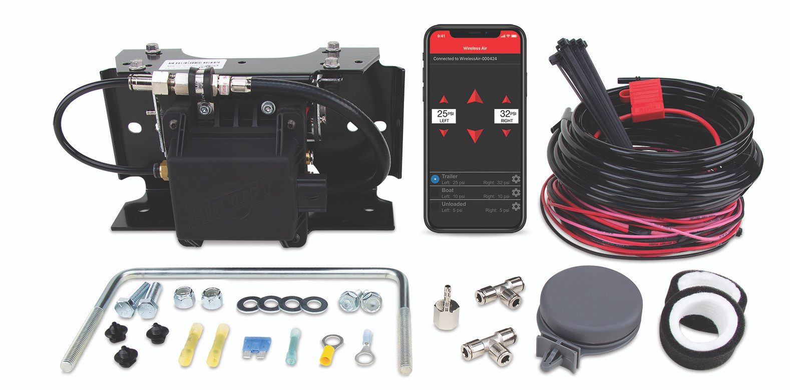





Always the correct part
We know our products
Quality Products
Free Shipping!
Always the correct part
We know our products
Quality Products
Free Shipping!
Quick Ship
In stock and ready to ship — order now!
FREE ShippingFREE SHIPPING
Estimated delivery Thu, Oct 22 - Sun, Oct 25
Order before 2 PM EST Monday–Friday for same-day processing
Guaranteed safe & secure checkout
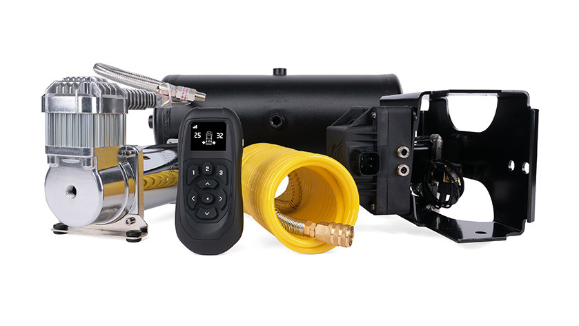
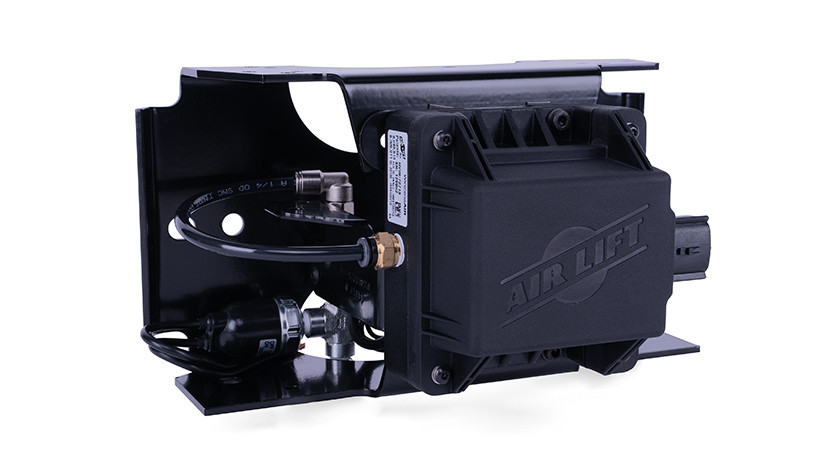
The WirelessAir Tank + EZ Mount by Air Lift integrates a manifold and compressor into a dual tank system, equipped with the necessary wiring harness and accessories to enable real-time monitoring and inflation/deflation of air springs.

Never search for an air compressor again during a long road trip. Fine-tune and easily monitor your air spring’s pressure with Air Lift’s WirelessAir Tank + EZ Mount. This is an all-in-one solution combining a manifold and compressor into a tank system, with everything needed for seamless connection to your vehicle's power source and air springs of most brands. Adjusting the air pressure can be inconvenient without an air compressor, trying to find a gas station with an air compressor, then fiddle with Schrader valves until the pressures are equalized. Air Lift eliminated that hassle with WirelessAir, making every part of the process simple. The WirelessAir features a powerful 444c heavy-duty compressor, a 2-gallon powder-coated reserve tank, and its dual-path system inflates or deflates air springs to individual pressures. This is ideal for vehicles carrying loads unequally distributed left-to-right or trailers weighed heavily on one side. A mobile app for iOS and Android devices is available on top of the included wireless controller, allowing you to connect to the manifold easily. In addition, the controller and app are programmable with user-defined presets so WirelessAir can remember your frequently used pressures. WirelessAir Tank + EZ Mount packages the manifold and solenoid assembly into one convenient, pre-assembled, and factory-tested EZ Mount bracket. The kit also features a remote mount Shrader valve and a coiled hose with quick connect to run accessories such as filling tires, inflatables, or running small air tools. For over 70 years, Air Lift has been the leader in air suspension products and is committed to delivering quality parts that last. The system comes with a two-year warranty and a 60-day, no-questions-asked, money-back guarantee, not to mention Air Lift's reputation for excellent customer service and technical support, should you run into any snags in the installation process.
Air Lift Company has developed dependable air spring suspension products since our inception in 1949. Our original product, a rubber air spring inserted into a car’s factory coil spring, was created and patented in 1950. We’ve come a long way since 1949 and are proud to be a dedicated suspension specialist company.
Today, Air Lift load support products are sold worldwide and are engineered to fit over 540 vehicles. Our extensive product line offers air helper springs for trucks, RVs, SUVs, CUVs, and vans, as well as the most technologically advanced on-board air compressor systems for on-the-go air spring control.
Air Lift leads the industry in no-drill applications – kits that bolt onto your vehicle’s frame, speeding the installation process. Our teams work constantly to bring innovative products to you and upgrade existing products with the latest technology.
All of our efforts are spent ensuring your safety and comfort by designing, engineering, and manufacturing the highest quality suspension products. We are a family-owned business based in Lansing, Michigan, and make your family and cargo’s safety our top priority.
Experts available to answer your questions
Call 888-634-94942 Year Limited
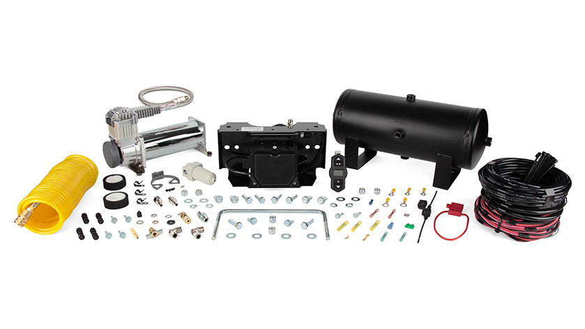
The WirelessAIR™ Tank System combines a manifold and compressor into a 2-gallon tank system with a wiring harness and accessories to connect to vehicle power and air springs (which are purchased separately). Kit 74100 is an upgrade system for existing installations; kit 74100EZ includes an EZ Mount assembly and wireless display. Both kits include the compressor (16544), tank (11175), harness (26927), air lines, fittings, hardware, and electrical components.
The system is designed for cars and trucks as specified by Air Lift Company. The upgrade kit (74100) is specifically for vehicles equipped with Standalone Kit 74000 or EZ Mount Kit 74000EZ. Air springs must be purchased separately. The manual does not provide a detailed vehicle compatibility list; contact Air Lift customer service at (800) 248-0892 for specific fitment confirmation.
Required tools include: power drill, 1/4" and 3/8" drill bits, grinder, standard wrench set, 3/8", 1/2", 5/16", and 9/16" sockets and ratchet, 3/32" hex key, wire stripping/crimping tool, sharp razor knife, lighter or torch, and Teflon tape. A hose cutter is recommended for cutting air lines cleanly.
Yes. The manual states: "DISCONNECT THE BATTERY GROUND BEFORE INSTALLING THE SYSTEM." Additionally, remove all fuses when jump-starting or welding on the vehicle to prevent damage to the manifold.
Yes. Drilling is required to mount the tank, compressor, and EZ Mount assembly to the vehicle frame. The manual provides drilling templates for the compressor (16544), EZ Mount assembly (26566), and tank (11175). Before drilling, you must ensure the back side of the frame rail is clear of brake lines, fuel lines, wiring, and other vehicle components. Pilot holes are made with 1/4" drill bits; final holes for thru-bolts use 3/8" drill bits.
Tank thru-bolt torque: 21-25 lb.-ft. (30-34 Nm). EZ Mount hex cap bolt torque: 21-25 lb.-ft. (30-34 Nm). EZ Mount U-bolt torque: 4-6 lb.-ft. (5.4-8.1 Nm). EZ Mount solenoid bracket hex screws: 23 in.-lbs. Filter assembly to bracket: 18-24 in.-lbs. Self-tapping screws have no torque specification due to variables. Air line fittings are installed 1½-2 turns beyond finger-tight.
The system uses a 30A spade fuse (24547) in the ATC fuse holder (24500) for main power and a 3A ATM fuse (24503) in the HHL fuse holder (24501) for ignition. The fuse holder connects to the vehicle's fuse box using either adapter #1 (24542, for standard ATC-type fuses) or adapter #2 (24561, for smaller mini-type fuses). Do not install the main fuse until all connections are complete.
Tanks accumulate water from moisture and must be periodically drained using the drain cock (II). The filter (HH) will collect water and needs to be manually drained periodically to prevent damage to other system components. The manual does not specify a drainage interval; contact Air Lift customer service for recommended maintenance schedules.
The 74100 upgrade kit includes: 2-gallon air tank (11175), compressor 444C chrome (16544), wireless air tank harness (26927), tire fill air line coiled (22043), 1/4" air line 30 feet (20230), and multiple hardware packs containing fittings, fasteners, electrical connectors, fuses, and zip ties. The 74100EZ kit additionally includes an EZ Mount assembly (26566) and Wireless Air Display (73006). Air springs are not included and must be purchased separately.
Yes. Air springs are not included with either the 74100 or 74100EZ kit and must be purchased separately. The system provides the tank, compressor, manifold, and wiring to connect to air springs, but the springs themselves are not part of the kit.
Yes. The 74100 upgrade kit is designed to upgrade existing systems. If you have a vehicle equipped with Standalone Kit 74000 or EZ Mount Kit 74000EZ, you can upgrade to the tank system. The upgrade process requires removing your existing compressor, wiring harness, and electrical connections before installation. Contact Air Lift customer service at (800) 248-0892 to confirm your current system is compatible.
Ideally, mount the tank system in the middle of the vehicle to optimize wireless performance. The manifold assembly (EZ Mount) and tank assembly must be no longer than 6 feet apart based on wiring length. Keep all components at least 6 inches away from heat sources such as the exhaust. Avoid routing air lines and wiring near sharp edges. Support wiring and air lines every 8-12 inches with zip ties. The manual provides a suggested component layout diagram; your specific layout may vary based on your vehicle.
Before drilling any holes, ensure the back side of the frame rail is completely clear of vehicle components, including brake lines, fuel lines, wiring, and other systems. This is critical to avoid damaging essential vehicle systems. The manual emphasizes this check multiple times throughout the installation process. Use the provided drilling templates to mark hole locations accurately.
The manual does not explicitly state whether professional installation is required. However, the installation involves drilling, electrical wiring, pneumatic connections, and torque specifications. The manual recommends reading the entire installation guide before beginning. If you are not comfortable with drilling, electrical work, or pneumatic systems, professional installation is advisable. Contact Air Lift customer service at (800) 248-0892 for installation assistance.
No. The EZ Mount assembly can be mounted in any orientation except with the Air Lift logo upside down or with the Air Lift logo facing the ground. Do not hang the EZ Mount from a horizontal surface using self-tapping screws. The assembly can be mounted horizontally or vertically on the vehicle frame using hex cap bolts, U-bolts, or self-tapping screws.
The EZ Mount ships in vertical orientation. To mount horizontally: 1) Remove the air line between the elbow fitting and manifold. 2) Remove the 4 screws mounting the manifold to the bracket. 3) Remove the 2 hex screws from the solenoid valve bracket using a 3/32" hex wrench (ensure it is fully seated to avoid stripping). 4) Reinstall the solenoid assembly in the other hole pattern on the bracket. 5) Torque the hex screws to 23 in.-lbs. 6) Reassemble the manifold to the bracket with the 4 original screws, torqued to 23 in.-lbs. 7) Cut a 10-12" piece of air line and connect between the elbow fitting and manifold.
Install all fittings 1½-2 turns beyond finger-tight. Never back out a fitting after it is installed because it could cause a leak. When installing fittings with threads, apply Teflon tape or pipe dope. For the filter assembly, ensure the arrow on top of the filter points toward the manifold/EZ Mount. When assembling the remote filter/pressure switch/solenoid assembly (upgrade systems), ensure the filter and solenoid are both in the same vertical direction as shown in the manual.
1) Attach the air filter to the compressor inlet port if mounting inside the vehicle. If mounting outside, snorkel the inlet filter to a dry location inside the vehicle using components supplied with the compressor. 2) Center-punch and drill four holes using the compressor drilling template (Fig. 19). 3) Secure the compressor using supplied hardware. If not installing the leader line directly to the tank, attach the straight PTC fitting (KK) to the end of the leader line, applying tape or pipe dope and installing 1½-2 turns beyond finger-tight. Before drilling, ensure the back side of the frame rail is clear of brake lines, fuel lines, and wiring.
1) Determine the tank's mounting direction before installing fittings. 2) Install the drain cock (II) into the port meant to point to the ground, applying tape or pipe dope, 1½-2 turns beyond finger-tight. 3) Install the blow off valve (GG) across the belly of the tank using one of the other available ports, tightened 1½ turns beyond finger-tight. Do not install it adjacent to the feet. 4) Install a 1/4" MNPT X 1/4" PTC elbow fitting (FF) to the last belly port for manual fill. 5) For tank kits (not upgrades), install a 1/4" hex nipple (JJ) from the tank to the filter (HH), then an elbow fitting (FF) from the filter to the end port facing the manifold, ensuring the filter arrow points to the EZ Mount. 6) If the compressor leader line cannot reach the tank directly, install an elbow fitting (FF) on the last end port.
1) Use the drilling template (Fig. 22) to pre-drill mounting holes. 2) You have two mounting options: a) Hex cap screw (N), flat washer (M), lock washer (P), and lock nut (L); or b) Self-threading screw (O) and lock washer (P). 3) If using self-threading screws, use a 1/4" drill bit to make pilot holes. 4) If using thru bolts, drill a hole using a 3/8" drill bit and torque to 21-25 lb.-ft. (30-34 Nm). Self-tapping screws have no torque specification due to variables. Before drilling, ensure the back side of the frame rail is clear of brake lines, fuel lines, and wiring.
1) Locate the bracket position based on your component layout. 2) Use the bracket as a template to mark the frame where you want to install it. 3) Drill two pilot holes with a 1/4" drill bit. 4) Install 2 self-threading screws (6A). There is no torque specification for self-tapping screws due to variables. Before drilling, ensure the back side of the frame rail is clear of brake lines, fuel lines, and wiring.
The EZ Mount can be mounted using three methods: 1) Hex cap bolts (3B) with flat washers (5B) and nylon lock nuts (4B), torqued to 21-25 lb.-ft. (30-34 Nm); 2) U-bolt (2B) with washers (5B) and nylon lock nuts (4B), torqued to 4-6 lb.-ft. (5.4-8.1 Nm); or 3) Self-tapping screws (6B) with no torque specification. Use the drilling template (Figs. 20-21) for mounting with self-threading screws or hex cap bolts. For self-tapping screws, use a 1/4" drill bit to make pilot holes. Before drilling from the frame, ensure the back side is clear of brake lines, fuel lines, and wiring.
1) Attach the wiring harness to the top (preferred) or bottom of the EZ Mount bracket with zip ties (E). 2) Route the harness underneath the vehicle on either the passenger's (right) or driver's (left) side based on your component layout. 3) Route battery power (red), ground (black), and ignition wire (pink) from the frame rail up to the engine compartment where the battery and fuse box are located. 4) Ensure you have enough wire length to integrate into those locations without extending the wires. 5) Attach the harness to secure components every 6-8" all the way down to where you mounted the tank/manifold/compressor. Do not extend electrical wiring, as this could result in system function issues.
Install the connector off the main harness (B) to the manifold. You should hear an audible click when attaching the connector to the manifold, indicating a secure connection.
Crimp the red butt connectors (DD) between the solenoid valve and the main harness wires labeled solenoid valve. Apply heat to the butt connectors to seal them.
The pressure switch has two black wires. 1) Crimp the blue butt connector (X) to one of the black wires. Apply heat to the butt connector to seal it. 2) To the other black wire on the pressure switch, crimp a yellow ring terminal (W) to the end. 3) Attach this ring terminal to the frame using a self-tapping screw (Q). This must have a good ground connection to the frame. It may be necessary to grind some paint or rust off the frame to make a good connection.
1) Cut off the terminals on the compressor before attaching to the main harness. 2) Crimp the yellow butt connectors (V) between the compressor and the main harness compressor wires, connecting black to black and red/white to red. 3) Apply heat to the butt connectors to seal them.
1) Crimp the yellow butt connector (V) to the red power wire on the main harness. 2) Crimp the other end to the red ATC fuse holder (R) after cutting the wire to split it into two equal halves. 3) Apply heat to the butt connector to seal it. 4) Crimp the yellow 3/8" (CC) or 1/4" (W) ring terminal to the other side of the red wire on the ATC fuse holder. 5) Attach the ring terminal to the positive battery post. Do not install the fuse at this time.
Crimp the yellow 3/8" (CC) or 1/4" (W) ring terminal to the black ground wire on the main harness. Attach the ring terminal to the ground battery post.
1) Crimp the blue butt connector (X) to the pink ignition wire on the main harness. 2) Crimp the other end to one of the black mini fuse holder (S) ends. 3) Apply heat to the butt connector to seal it. 4) Determine the correct fuse adapter type for your vehicle's fuses (adapter #1 for standard ATC-type fuses, adapter #2 for smaller mini-type fuses). 5) Install the 3A ATM fuse (24503) into the adapter (BB or AA), then install the fuse back into the fuse box. 6) Connect the end of the fuse holder with the female push-on connector (Y or Z) onto the adapter.
Adapter #1 (24542) is used for standard ATC-type fuses and requires a 1/4" (14-16 GA) female connector (Z). Adapter #2 (24561) is used for smaller mini-type fuses and requires a 3/16" (14-16 GA) female connector (Y). Determine which type of fuses your vehicle uses and select the appropriate adapter. Both adapters and connectors are supplied in the kit.
1) Determine the location for the auxiliary port. 2) Cut a length of air line to reach from the elbow fitting in the tank to this desired location. 3) Make clean, square cuts with a razor blade or hose cutter; do not use scissors or wire cutters. 4) Install one end of the air line into the elbow fitting. 5) Use zip ties to secure the air line to fixed points along the chassis. Do not pinch or kink the air line. The minimum bend radius is 1" (25 mm). Leave at least 2" (50 mm) of slack in the air line to allow for movement. 6) Install the Schrader valve in the chosen location. 7) Attach the other end of the air line into the Schrader valve.
The Schrader valve is installed in a 5/16" (8 mm) hole in the vehicle body or bumper. Use the supplied hardware: hex nuts (J), flat washer (G), star washer (H), and rubber washer (K). Insert the Schrader valve through the hole and secure with the hardware. Attach the air line from the tank's elbow fitting to the Schrader valve. Install the cap (I) on the Schrader valve when not in use.
Use a sharp knife or hose cutter and make clean, square cuts. Do not use scissors or wire cutters because these tools will deform the air line. Do not cut the lines at an angle. The minimum bend radius for 1/4" air line is 1" (25 mm). Air lines are to be installed straight into fittings. Inspect the air line for scratches that run lengthwise. Contact Air Lift customer service if the air line is damaged. A video demonstrating proper air line cutting is available at air-lift.co/cuttingairline.
Refer to the Installation Diagram (Fig. 12) for complete air line routing instructions. Avoid routing air lines near sharp edges. If passing air lines through holes in the frame, use rubber grommets (not supplied). Support air lines every 8-12" (200-300 mm) with zip ties or other means. Keep air lines at least 6" away from heat sources such as the exhaust. The minimum bend radius for air line is 1" (25 mm). Leave at least 2" (50 mm) of slack in the air line to allow for movement that might pull on the line.
After all connections are made and fuses are installed, refer to the WirelessAIR™ User Guide (AD-963) included with your kit to learn how to operate the system, connect the wireless controller, and connect your mobile device to the system. The User Guide covers pairing your supported Apple or Android device or wireless controller. Ensure all electrical connections are secure and all air line connections are tight before operating the system.
Remove all fuses from the system before jump-starting or welding on the vehicle. Failure to do so could damage the manifold. Reinstall the fuses after the jump-start or welding is complete.
The manual states that tanks accumulate water from moisture and the filter will collect water, and both need to be periodically drained to prevent damage to other system components. However, the manual does not specify a drainage interval (e.g., monthly, quarterly, annually). Contact Air Lift customer service at (800) 248-0892 for recommended maintenance schedules based on your climate and usage.
The blow off valve (GG) is rated at 175 PSI. The pressure switch (11A) is rated at 110-145 PSI. These components protect the system from overpressure. The manual does not specify an overall system maximum pressure rating; contact Air Lift customer service at (800) 248-0892 for additional pressure specifications.
The air tank (11175) has a 2-gallon capacity.
Disconnect the battery ground before installing the system. Wear appropriate safety equipment when drilling, grinding, and working with electrical components. Ensure the back side of the frame rail is clear of brake lines, fuel lines, and wiring before drilling. Use a fully seated hex wrench when removing solenoid bracket screws to avoid stripping the screw heads. Protect air lines and wiring when routing near sharp edges. Keep all components at least 6 inches away from heat sources such as the exhaust. Locate the EZ Mount in an area shielded from direct splash, as excessive moisture can damage the compressor and cause system failure.
Use the drain cock (II) installed on the tank port that points to the ground. Open the drain cock to release accumulated water and moisture from the tank. The manual does not specify a drainage interval; periodic draining is recommended to prevent water damage to other system components.
The filter (HH) will collect water and needs to be manually drained periodically. The manual does not provide specific instructions for draining the filter or specify a drainage interval. Contact Air Lift customer service at (800) 248-0892 for detailed filter maintenance procedures.
If you do not hear an audible click when attaching the manifold connector to the manifold, the connection may not be secure. Disconnect and reattach the connector, ensuring it is fully seated. You should hear a distinct click indicating a proper connection. If the connector still does not click, contact Air Lift customer service at (800) 248-0892.
The manual states: "NEVER BACK OUT A FITTING AFTER IT IS INSTALLED BECAUSE IT COULD CAUSE A LEAK." If a leak occurs, do not attempt to back out the fitting. Contact Air Lift customer service at (800) 248-0892 for assistance. Ensure all fittings are installed 1½-2 turns beyond finger-tight and that Teflon tape or pipe dope is applied to threaded fittings.
Do not use scissors or wire cutters to cut air lines, as these tools will deform the air line. Use a sharp knife or hose cutter and make clean, square cuts. Inspect the air line for scratches that run lengthwise. If the air line is damaged, contact Air Lift customer service at (800) 248-0892 for a replacement.
The pressure switch must have a good ground connection to the frame. If the connection is poor, it may be necessary to grind some paint or rust off the frame to make a good connection. Use a self-tapping screw (Q) to attach the yellow ring terminal (W) from the pressure switch to the frame. Ensure the connection is clean and tight.
Ensure all electrical connections are secure and properly crimped with heat-sealed butt connectors. Verify that all fuses are installed correctly and that the fuse types match the specifications (30A for main power, 3A for ignition). Check that the manifold connector is fully seated and clicks into place. Ensure the battery is properly connected and that the battery ground was disconnected before installation. If the system still does not function, contact Air Lift customer service at (800) 248-0892 for technical assistance.
The manual states that ideally, tank systems should be mounted in the middle of the vehicle to optimize wireless performance. If wireless performance is poor, verify that the system is mounted as centrally as possible in the vehicle. Avoid mounting the system near metal structures or other wireless devices that may cause interference. If performance remains poor, contact Air Lift customer service at (800) 248-0892.
The manual warns: "MAKE SURE THE HEX WRENCH IS FULLY SEATED SO AS NOT TO STRIP THE HEAD OF THE SCREW SINCE IT WILL BE USED ON THE RE-ASSEMBLY PROCESS." If a screw head is stripped, contact Air Lift customer service at (800) 248-0892 for a replacement screw. Use a fully seated 3/32" hex wrench when removing or installing solenoid bracket screws to prevent stripping.
If the compressor is mounted outside the vehicle, snorkel the inlet air filter to a dry location inside the vehicle using components supplied with the compressor. This reduces moisture drawn into the tank. If the compressor is mounted inside the vehicle, attach the air filter to the port on the end of the compressor. Ensure the filter location is dry and away from any heat source, with air inlet slots free from blockage.
Check all air line fittings to ensure they are installed 1½-2 turns beyond finger-tight. Verify that Teflon tape or pipe dope was applied to all threaded fittings. Inspect all air lines for damage, scratches, or kinks. Ensure the drain cock (II) on the tank is fully closed. Check that the blow off valve (GG) is not leaking (it is rated at 175 PSI). If the system still does not hold pressure, contact Air Lift customer service at (800) 248-0892.
If the manifold connector does not produce an audible click when attached to the manifold, the connection may not be secure. Disconnect the connector and reattach it, ensuring it is fully seated. You should hear a distinct click. If the connector still does not click or if the connection feels loose, contact Air Lift customer service at (800) 248-0892.
If the main 30A fuse (24547) or ignition 3A fuse (24503) blows repeatedly, there may be a short circuit in the wiring or a component failure. Do not install a fuse with a higher amperage rating. Check all electrical connections for loose, damaged, or corroded terminals. Verify that the battery connections are secure and properly crimped. If the fuse continues to blow, contact Air Lift customer service at (800) 248-0892 for technical assistance.
No reviews have been added for this product.
