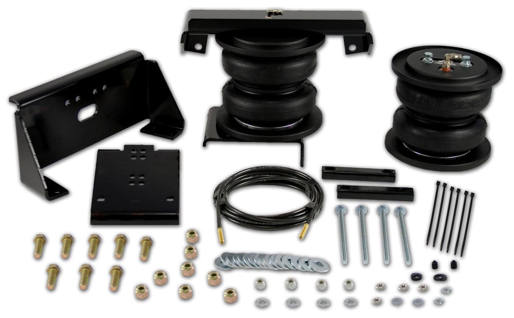
Air Lift LOADLIFTER 5000 57410Air LiftOriginal price was $940.99. Current price is $681.99.In Stock
View productOur in-house experts typically reply within one business day.

Air Lift
Verify Fitment
Select your vehicle to confirm this part fits.
2005 - 2009 Ford F-250 Super Duty
Confirmed to Fit
2005 - 2010 Ford F-250 Super Duty
Confirmed to Fit
2005 - 2010 Ford F-350 Super Duty
Confirmed to Fit
2005 - 2010 Ford F-350 Super Duty
Confirmed to Fit


Always the correct part
We know our products
Quality Products
Free Shipping!
Always the correct part
We know our products
Quality Products
Free Shipping!
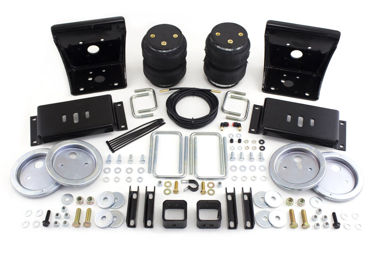
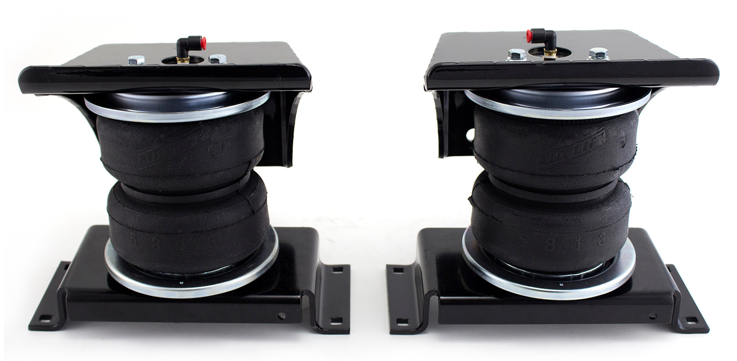
LoadLifter 5000 Air Spring Kit

Air Lift adjustable air helper springs level your load, and give your truck, van, or SUV a safer, more comfortable ride. Air springs are easy to install between your existing springs and the vehicle frame. Just add air when towing or hauling a heavy load, and reduce air pressure when unloaded, they are fully adjustable for a great ride. Air Lift air springs eliminate sag, sway, and bottoming out. They are made with rugged, durable components for long, reliable service. LoadLifter 5000 kits are Air Lift's heaviest-rated kits for hauling or towing heavy loads. They have up to 5,000 pounds of leveling capacity, right up to the manufacturer's recommended Gross Vehicle Weight Rating, and are air adjustable from 5 to 100 PSI. LoadLifter 5000 kits fit such popular vehicles as ton and one-ton pickup trucks, many Class A, B & C motor homes, and commercial trucks and other severe uses. They also come standard with a limited lifetime warranty and an exclusive 60 day ride satisfaction guarantee.
Air Lift Company has developed dependable air spring suspension products since our inception in 1949. Our original product, a rubber air spring inserted into a car’s factory coil spring, was created and patented in 1950. We’ve come a long way since 1949 and are proud to be a dedicated suspension specialist company.
Today, Air Lift load support products are sold worldwide and are engineered to fit over 540 vehicles. Our extensive product line offers air helper springs for trucks, RVs, SUVs, CUVs, and vans, as well as the most technologically advanced on-board air compressor systems for on-the-go air spring control.
Air Lift leads the industry in no-drill applications – kits that bolt onto your vehicle’s frame, speeding the installation process. Our teams work constantly to bring innovative products to you and upgrade existing products with the latest technology.
All of our efforts are spent ensuring your safety and comfort by designing, engineering, and manufacturing the highest quality suspension products. We are a family-owned business based in Lansing, Michigan, and make your family and cargo’s safety our top priority.
Experts available to answer your questions
Call 888-634-9494Limited Lifetime
4 compatible vehicles
| Year | Make & Model | Notes |
|---|---|---|
| 2005 - 2009 | Ford F-250 Super Duty | Also Fits Reese 5th Wheel Hitch Except Signature Series And Hitches w/Cstm Rail Kit w/No Hitch |
| 2005 - 2010 | Ford F-250 Super Duty | w/No Hitch Also Fits Reese 5th Wheel Hitch Except Signature Series And Hitches w/Cstm Rail Kit |
| 2005 - 2010 | Ford F-350 Super Duty | Also Fits Reese 5th Wheel Hitch Except Signature Series And Hitches w/Cstm Rail Kit w/No Hitch |
| 2005 - 2010 | Ford F-350 Super Duty | w/No Hitch Also Fits Reese 5th Wheel Hitch Except Signature Series And Hitches w/Cstm Rail Kit |
Yes, the Air Lift LOADLIFTER 5000 57212 (Part #BBCG57212) is designed to fit the 2005-2010 Ford F-250 Super Duty.
The Air Lift LOADLIFTER 5000 57212 (Part #BBCG57212) fits 2005-2010 Ford F-250 Super Duty models. The 2010 model year is the last year covered by this part number. For newer models, check for an updated version.
The Air Lift LOADLIFTER 5000 57212 (Part #BBCG57212) fits the following vehicles: 2005-2010 Ford F-250 Super Duty; 2005-2010 Ford F-350 Super Duty. Always verify your specific year, make, and model before ordering.
The Air Lift LOADLIFTER 5000 57212 (Part #BBCG57212) Refer to the included instructions for installation details. Basic hand tools are typically all you need.
The LoadLifter 5000 is an air spring suspension support system designed for 3/4-ton and 1-ton pickups and SUVs with leaf springs, as well as motor home rear applications and some front applications. It uses reinforced, commercial-grade convolute bellows (single or double depending on the kit) manufactured with layers of rubber and cords. The system provides up to 5,000 pounds of load leveling support with air adjustability from 5 to 100 PSI (0.34–6.9 BAR). It helps level the vehicle under load and improves ride comfort and stability.
There must be at least 8 inches (203mm) of clearance between the tire and the frame to install the LoadLifter 5000 kit. This is a critical requirement that must be verified before beginning installation.
Yes, the LoadLifter 5000 is compatible with 2008 and later Ford vehicles. However, these vehicles require drilling a 3/8" locating hole for the upper bracket using a template provided in the manual. The template must be printed at 100% scale to ensure accurate hole placement. Before drilling, you must check the back side of the frame for clearance issues with brake lines, gas lines, and electrical lines, and temporarily relocate any obstacles.
No. The installation of the LoadLifter 5000 does not alter the gross vehicle weight rating (GVWR) or payload of the vehicle. You must check your vehicle's owner's manual and never exceed the maximum load listed for your vehicle. Exceeding the GVWR is dangerous and voids the Air Lift warranty.
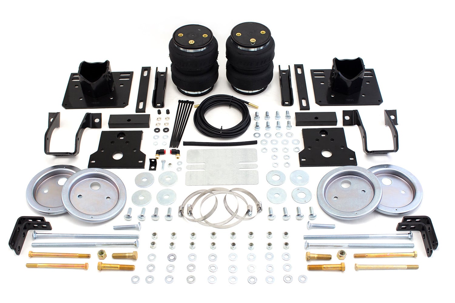
The kit includes: 2 air springs (58437), 2 upper brackets (07178), 2 lower brackets (03102), 4 roll plates (11951), 2 elbow fittings (21837), 4 short 2" U-bolts (10594), 4 long 4.5" U-bolts (10561), 12 3/8" nylon lock nuts (18435), 8 3/8" flat washers (18444), 8 3/8" lock washers (18427), 2 jounce bumper spacers (10014), 2 3/8" large flat washers (18447), 2 3/8" x 1.5" WHFB bolts (17159), 8 3/8" x 7/8" hex-head cap screws (17203), 4 spacer bars (01525), 2 3/8"-16 x 1.25" hex-head cap screws (17202), 4 3/8" flat washers (18468), 8 1/2" large flat washers (18207), 4 1/2" nylon lock nuts (18460), 4 1/2"-13 x 1.75" hex-head cap screws (17247), 1 5/8" diameter clip (10465), 1 air line assembly (20086), 6 zip ties (10466), 2 valve caps (21230), 2 M8 flat washers (18501), 2 rubber washers (21234), 2 small star washers (18411), and 4 5/16" hex nuts (21233).
The manual specifies a 9/16" open-ended wrench for securing the air spring to brackets. It also references a valve core tool for checking the valve core during leak diagnosis. The manual mentions using a sharp knife or hose cutter for cutting air lines (not scissors or wire cutters), pliers or vice grips for removing air lines from barbed fittings, and a wrench for tightening the swivel fitting. A center punch and drill are needed for drilling holes (3/8" and 1/2" holes for frame mounting, and 5/16" holes for inflation valves). Jack stands are required to raise and support the vehicle.
1. Raise the vehicle and remove the wheels. 2. Obtain normal ride height using jack stands. 3. Remove the emergency brake cable bracket from the driver side spring retainer and save the bolt for later use. 4. Remove both jounce bumpers from under the frame above the axle and save them for later use. 5. Verify at least 8 inches (203mm) of clearance between the tire and frame. 6. For 2008 and later Ford vehicles, prepare to use the drilling template provided in the manual (printed at 100% scale).
1. Set a roll plate (D) on both ends of the air spring (A) with the radiused (rounded) edge toward the air spring so it is seated in both roll plates. 2. Install a 90-degree swivel air fitting (E) finger tight plus 1.5 turns—do not overtighten. 3. Place the upper bracket (B) onto the top of the air spring and roll plate with the legs facing down. 4. Set the air spring on the lower bracket (C), aligning the two holes in the base of the air spring with the two outer slots in the top of the lower bracket. 5. Attach the upper bracket to the assembly using flat washers (I), lock washers (J), and hex-head bolts (N), and tighten securely. 6. Loosely attach the lower bracket to the assembly using flat washers (I), lock washers (J), and hex-head bolts (N). The flange on the bracket must face the outside (tire side) of the vehicle.
The distance between the upper bracket and lower bracket (measured as distances X and Y) must be 6.5 to 8 inches (165–203mm). It is best to use the highest envelope available between the brackets. The distances X and Y must be equal on both sides, and the brackets must be parallel to each other. Failure to mount the air spring at or higher than 6.5 inches (165mm) can result in the air spring bottoming out.
Use a spacer bar (O) if the lower bracket touches the tops of the stock U-bolts and does not fit flush to the leaf spring, or if the mounting distance is more than 8 inches (203mm). The spacer bar spaces the lower bracket so it will clear the stock U-bolts. Place the spacer bar on the leaf spring and attach the lower bracket securely using the provided U-bolts (F or G), flat washers (I), and nylon lock nuts (H), torqued to 16 lb.-ft (22Nm).
1. Set the assembly back on the spring. 2. Attach the upper bracket using one 3/8" bolt (M), flat washer (L), and nylon lock nut (H). Also attach using two 1/2" bolts (T), four flat washers (R), and two nylon lock nuts (S). 3. Torque the 3/8" bolt to 44 lb.-ft (60Nm). 4. Torque the 1/2" bolts to 95 lb.-ft (129Nm). For 2008 and later Ford vehicles, use the provided template to locate and drill a 3/8" hole in the frame rail before attaching. Before drilling, check the back side of the frame for clearance issues with brake lines, gas lines, and electrical lines, and temporarily relocate any obstacles.
1. Position the lower bracket so it is parallel with the upper bracket and the air spring is perpendicular to both. Move the air spring in and out using the slots in the lower bracket to achieve proper alignment. 2. If the spacer bar (O) is not used, attach the lower bracket securely using the provided U-bolts (F or G), flat washers (I), and nylon lock nuts (H), and torque to 16 lb.-ft (22Nm). You can use the shorter U-bolts (F) when attaching to frame contact overloads. 3. If the spacer bar (O) is used, place the spacer on the leaf spring and attach the lower bracket securely using the provided U-bolts (F or G), flat washers (I), and nylon lock nuts (H), and torque to 16 lb.-ft (22Nm). Depending on the thickness of the leaf spring stack, it may be necessary to trim the U-bolts.
1. Attach the supplied clamp (V) around the emergency brake cable and secure it to the lower bracket using the previously removed stock bolt. Tighten securely. 2. Cut off the existing emergency brake cable bracket close to the cable. This prevents interference with the new air spring installation.
1. One side of the jounce bumper spacer (K) has two holes in it. Attach the previously removed jounce bumper to this side using the previously removed hardware and tighten securely. 2. Attach the assembly to the vehicle using the supplied 3/8" bolt (P), two 3/8" flat washers (Q), and a 3/8" nylon lock nut (H). 3. Repeat steps 1–2 for the other side of the vehicle.
Yes, drilling is required. You must drill two 1/2" holes in the frame for the upper bracket attachment. For 2008 and later Ford vehicles, you must also drill a 3/8" locating hole for the upper bracket using the template provided in the manual. Additionally, you must drill 5/16" holes to install the inflation valves at your chosen location (wheel well flanges, license plate recess, under gas cap, or through license plate). Before drilling any holes, check the back side of the frame for clearance issues with brake lines, gas lines, and electrical lines, and temporarily relocate any obstacles.
Yes, depending on the thickness of the leaf spring stack, it will be necessary to trim the U-bolts. Additionally, if the mounting distance is less than 6.5 inches (165mm), you will have to cut the tops of the U-bolts off and remove any spacers previously installed so the lower bracket sits flush on the leaf spring. The manual also notes that you may need to trim bolts to prevent bottoming out on the upper bracket.
Yes. After attaching the supplied clamp around the emergency brake cable and securing it to the lower bracket, you must cut off the existing emergency brake cable bracket close to the cable. This prevents interference with the new air spring installation.
Upper bracket 3/8" bolt: 44 lb.-ft (60Nm). Upper bracket 1/2" bolts: 95 lb.-ft (129Nm). Lower bracket U-bolts: 16 lb.-ft (22Nm). These torque values must be followed precisely to ensure proper installation and safety.
1. Choose a convenient location for mounting the inflation valves: wheel well flanges, license plate recess in bumper, under the gas cap access door, or through the license plate. Ensure there is enough clearance around the inflation valves for an air chuck. 2. Drill 5/16" holes to install the inflation valves. 3. Place a 5/16" nut and star washer on the air valve, leaving enough of the inflation valve in front of the nut to extend through the hole and have room for the rubber washer, flat washer, and 5/16" nut and cap. Approximately 1/2" (13mm) of valve should be exposed after installation to easily apply a pressure gauge or air chuck. 4. Push the inflation valve through the hole and use the rubber washer, flat washer, and another 5/16" nut to secure it in place. Tighten the nuts to secure the assembly.
1. Route the air line along the frame to the fitting on the air spring. Keep at least 6 inches (152mm) of clearance between the air line and the exhaust system. Avoid sharp bends and edges. 2. Use zip ties to secure the air line to fixed points along the chassis. Ensure the tie straps are tight but do not pinch the air line. Leave at least 2 inches (51mm) of slack to allow for any movement that might pull on the air line. 3. Cut off the air line, leaving approximately 12 inches (305mm) of extra air line. Make a clean square cut to prevent leaks. 4. Insert the air line into the 90-degree swivel fitting on the air spring. This is a push-to-connect fitting—simply push the air line into the fitting until it bottoms out. Approximately 9/16" of air line should be in the fitting.
Use a sharp knife or a hose cutter and make clean, square cuts. Do not use scissors or wire cutters because these tools may deform the air line, causing it to leak around fittings. Do not cut the lines at an angle. When removing air lines from barbed fittings, cut the air line off a few inches in front of the fitting and use pliers or vice grips to pull/twist the air line off the fitting. Do not cut off the air line completely as this will usually nick the barb and render the fitting useless. Inspect hose for scratches that run lengthwise on the hose prior to installation and contact Air Lift customer service at (800) 248-0892 if the air line is damaged.
Do not bend the 1/4" hose at a radius of less than 1 inch (25mm) or bend the 3/8" hose at a radius of less than 1.5 inches (38mm). The hose should be straight beyond the fitting for 1 inch (25mm) before bending. Do not put side load pressure on the fitting.
The minimum recommended air pressure is 5 PSI (0.34 BAR). The maximum air pressure is 100 PSI (6.9 BAR). Never exceed 100 PSI. For loaded vehicles (those with a heavy bed load, a trailer, or both), maintain at least 25 PSI (1.7 BAR). Operating the vehicle below the minimum air spring pressure of 5 PSI will void the Air Lift warranty.
Do not inflate the air springs until they have been properly secured to the vehicle. For initial leak testing, inflate the air springs to 30 PSI (2.1 BAR). After the leak test, deflate the springs to the minimum pressure required to restore the system to normal ride height, but do not deflate to lower than 5 PSI (0.34 BAR). For clearance and leak testing before road testing, inflate the air springs to 75–90 PSI (5.2–6.2 BAR).
Ensure at least 1/2 inch (13mm) of clearance from anything that might rub against each air spring sleeve. Be sure to check the tire, brakes, frame, shock absorbers, and brake cables. Additionally, maintain at least 6 inches (152mm) of clearance between the air springs and air lines and the exhaust system. Move the air spring in the slots of the lower brackets to align and make sure there is at least a thumbs width of clearance between the uninflated bag and the frame.
The vehicle can be lifted on a hoist for short-term service work such as tire rotation or oil changes. However, if the vehicle will be on the hoist for a prolonged period of time, support the axle with jack stands in order to take the tension off of the air springs. Additionally, if it becomes necessary to raise the vehicle by the frame, make sure the system is at minimum pressure (5 PSI [0.34 BAR]) to reduce the tension on the suspension/brake components. Use of on-board leveling systems do not require deflation or disconnection.
1. Clearance test: Inflate the air springs to 75–90 PSI (5.2–6.2 BAR) and ensure at least 1/2 inch (13mm) clearance from anything that might rub against each sleeve. Check the tire, brakes, frame, shock absorbers, and brake cables. 2. Leak test: Inflate the air springs to 75–90 PSI and check all connections for leaks. All leaks must be eliminated before road testing. 3. Heat test: Ensure sufficient clearance from heat sources, at least 6 inches (152mm) for air springs and air lines. If a heat shield was included, install it. 4. Fastener test: Recheck all bolts for proper torque. 5. Road test: Drive the vehicle 10 miles (16km) and recheck for clearance, loose fasteners, and air leaks.
1. Inflate the air spring to 30 PSI (2.1 BAR). 2. Spray all connections and the inflation valves with a solution of liquid dish soap and water. Spot leaks easily by looking for bubbles in the soapy water. 3. After the test, deflate the springs to the minimum pressure required to restore the system to normal ride height, but do not deflate to lower than 5 PSI (0.34 BAR). 4. Check the air pressure again after 24 hours. A 2–4 PSI (0.14–0.28 BAR) loss after initial installation is normal. Retest for leaks if the loss is more than 5 PSI (0.34 BAR).
1. Check air pressure weekly. 2. Always maintain normal ride height. Never inflate beyond 100 PSI (6.9 BAR). 3. If you develop an air leak, use a soapy water solution to check all air line connections and the inflation valve core before deflating and removing the air spring. 4. Loaded vehicles require at least 25 PSI (1.7 BAR). 5. When increasing load, always adjust air pressure to maintain normal ride height. 6. Always add air to springs in small quantities, checking the pressure frequently. 7. Periodically check the air spring system fasteners for tightness and check the air springs for any signs of rubbing. Realign if necessary. 8. On occasion, give the air springs a hard spray with a garden hose to remove mud, sand, gravel, or other debris. 9. Recheck the air spring system after 30 days or 500 miles (800km), whichever comes first. If any part shows signs of rubbing or abrasion, identify and move the source if possible. Check all fasteners for tightness.
The springs in the LoadLifter 5000 kit will support approximately 40 pounds (18kg) of load (combined on both springs) for each 1 PSI (0.07 BAR) of pressure. The required air pressure will vary depending on the state of the original suspension. Remember that loads carried behind the axle (including tongue loads) require more leveling force (pressure) than those carried directly over the axle.
Pressure determination comes down to three things: level vehicle, ride comfort, and stability. 1. Level vehicle: If the vehicle's headlights are shining into the trees or the vehicle is leaning to one side, raise the air pressure to correct either of these problems and level the vehicle. 2. Ride comfort: If the vehicle has a rough or harsh ride it may be due to either too much pressure or not enough. Try different pressures to determine the best ride comfort. 3. Stability: Stability translates into safety and should be the priority. Stability issues include roll control, bounce, dive during braking, and sponginess. Tuning out these problems usually requires an increase in pressure. Start with the vehicle level or slightly above. When in doubt, always add air. If the front of the vehicle dives while braking, increase the pressure in the front air bags if equipped. If it is suspected that the air bags have bottomed out, increase the pressure. Adjust the pressure up and down to find the best ride. If the vehicle rocks and rolls, adjust the air pressure to reduce movement. It may be necessary to maintain different pressures on each side of the vehicle. Loads such as water, fuel, and appliances will cause the vehicle to be heavier on one side. As much as a 50 PSI (3.5 BAR) difference is not uncommon.
Check for leaks by performing a leak test with soapy water on all air line connections, the threaded connection into the air spring, and all fittings in the control system. Ensure air lines are seated in connectors. Inspect fittings with soapy water. If there is a problem with the swivel fitting, trim 1 inch (25mm) off the end of the air line, ensure the cut is clean and square, and reinsert the air line into the push-to-connect fitting. If there is a problem with the threaded connection, tighten the swivel fitting another half turn. If it still leaks, deflate the air spring, remove the fitting, and re-coat the threads with thread sealant. Reinstall by hand tightening as much as possible and then use a wrench for an additional two turns. If the loss is more than 5 PSI (0.34 BAR) after 24 hours, there is a leak that must be fixed.
Look for a kink or fold in the air line. Replace any air line that has been kinked. If the air line is kinked, it will prevent proper inflation of that corner and may cause a leak.
1. Check the air line connection by deflating the spring and removing the line by pulling the collar against the fitting and pulling firmly on the air line. 2. Trim 1 inch (25mm) off the end of the air line. Be sure the cut is clean and square. 3. Reinsert the air line into the push-to-connect fitting. If the leak persists, check the threaded connection by tightening the swivel fitting another half turn. If it still leaks, deflate the air spring, remove the fitting, and re-coat the threads with thread sealant. Reinstall by hand tightening as much as possible and then use a wrench for an additional two turns.
1. Check the valve core by tightening it with a valve core tool. 2. Check the air line by removing the air line from the barbed type fitting. Cut the air line off a few inches in front of the fitting and use pliers or vice grips to pull/twist the air line off of the fitting. Do not cut off the air line completely as this will usually nick the barb and render the fitting useless. If the preceding steps have not resolved the problem, call Air Lift customer service at (800) 248-0892.
The LoadLifter 5000 is designed for 3/4-ton and 1-ton pickups and SUVs with leaf springs, motor home rear applications, and some front applications with leaf springs. Your vehicle must have at least 8 inches (203mm) of clearance between the tire and frame. For 2008 and later Ford vehicles, drilling is required using the provided template. Contact Air Lift at (800) 248-0892 to confirm fitment for your specific vehicle.
You will need: a 9/16" open-ended wrench, a center punch, a drill (for 3/8", 1/2", and 5/16" holes), a sharp knife or hose cutter, pliers or vice grips, a valve core tool, jack stands, and a wrench for tightening fittings. A compressor is needed to inflate the air springs, though any type of compressor that can produce sufficient pressure will work.
Upper bracket 3/8" bolt: 44 lb.-ft (60Nm). Upper bracket 1/2" bolts: 95 lb.-ft (129Nm). Lower bracket U-bolts: 16 lb.-ft (22Nm).
Minimum: 5 PSI (0.34 BAR). Maximum: 100 PSI (6.9 BAR). For loaded vehicles, maintain at least 25 PSI (1.7 BAR). Never exceed 100 PSI or the vehicle's GVWR.
Inflate to 75–90 PSI and check: 1/2" clearance from all rubbing surfaces (tire, brakes, frame, shocks, cables); all air line connections for leaks; all bolts for proper torque; and heat clearance (6" minimum from exhaust). Drive 10 miles and recheck clearance, fasteners, and leaks.
Check air pressure weekly. Maintain normal ride height and never exceed 100 PSI. Periodically check fasteners for tightness and air springs for rubbing. Recheck the system after 30 days or 500 miles (800km). Spray air springs with a garden hose occasionally to remove debris.
Possible causes: (1) Improperly installed air line, or air line has holes or cracks—solution: leak test the air line connections, the threaded connection into the air spring, and all fittings in the control system. (2) Air spring or tank leak, or fitting seal or air line is compromised—solution: check to make sure air lines are seated in connectors, inspect fittings with soapy water, trim hose or re-seal fitting, ensure lines are cut straight. A 2–4 PSI loss after initial installation is normal. If loss exceeds 5 PSI after 24 hours, there is a leak that must be fixed.
Cause: A kink or fold in the air line. Solution: Replace any air line that has been kinked. A kinked air line will prevent proper inflation of that corner and may cause a leak.
1. Check the air line connection: deflate the spring, remove the line by pulling the collar against the fitting and pulling firmly on the air line. 2. Trim 1 inch (25mm) off the end of the air line, ensuring the cut is clean and square. 3. Reinsert the air line into the push-to-connect fitting. If the leak persists, check the threaded connection by tightening the swivel fitting another half turn. If it still leaks, deflate the air spring, remove the fitting, re-coat the threads with thread sealant, and reinstall by hand tightening as much as possible, then use a wrench for an additional two turns.
1. Check the valve core by tightening it with a valve core tool. 2. Check the air line by removing it from the barbed type fitting. Cut the air line off a few inches in front of the fitting and use pliers or vice grips to pull/twist the air line off the fitting. Do not cut off the air line completely as this will usually nick the barb and render the fitting useless. If these steps do not resolve the problem, call Air Lift customer service at (800) 248-0892.
On Sale Today
Original price was $686.99. Current price is $497.99.You save $189.00 (28%)
Free Shipping
Ships free on all orders
 Authorized Dealer


Quick Ship
In stock and ready to ship — order now!
FREE ShippingFREE SHIPPING
Estimated delivery Wed, Sep 23 - Sat, Sep 26
Order before 2 PM EST Monday–Friday for same-day processing
Guaranteed safe & secure checkout
No reviews have been added for this product.