Air Lift Air Lift LoadLifter 5000 57354Air LiftOriginal price was $712.99. Current price is $516.99.In Stock
View productOur in-house experts typically reply within one business day.

Air Lift
Verify Fitment
Select your vehicle to confirm this part fits.


Always the correct part
We know our products
Quality Products
Free Shipping!
Always the correct part
We know our products
Quality Products
Free Shipping!
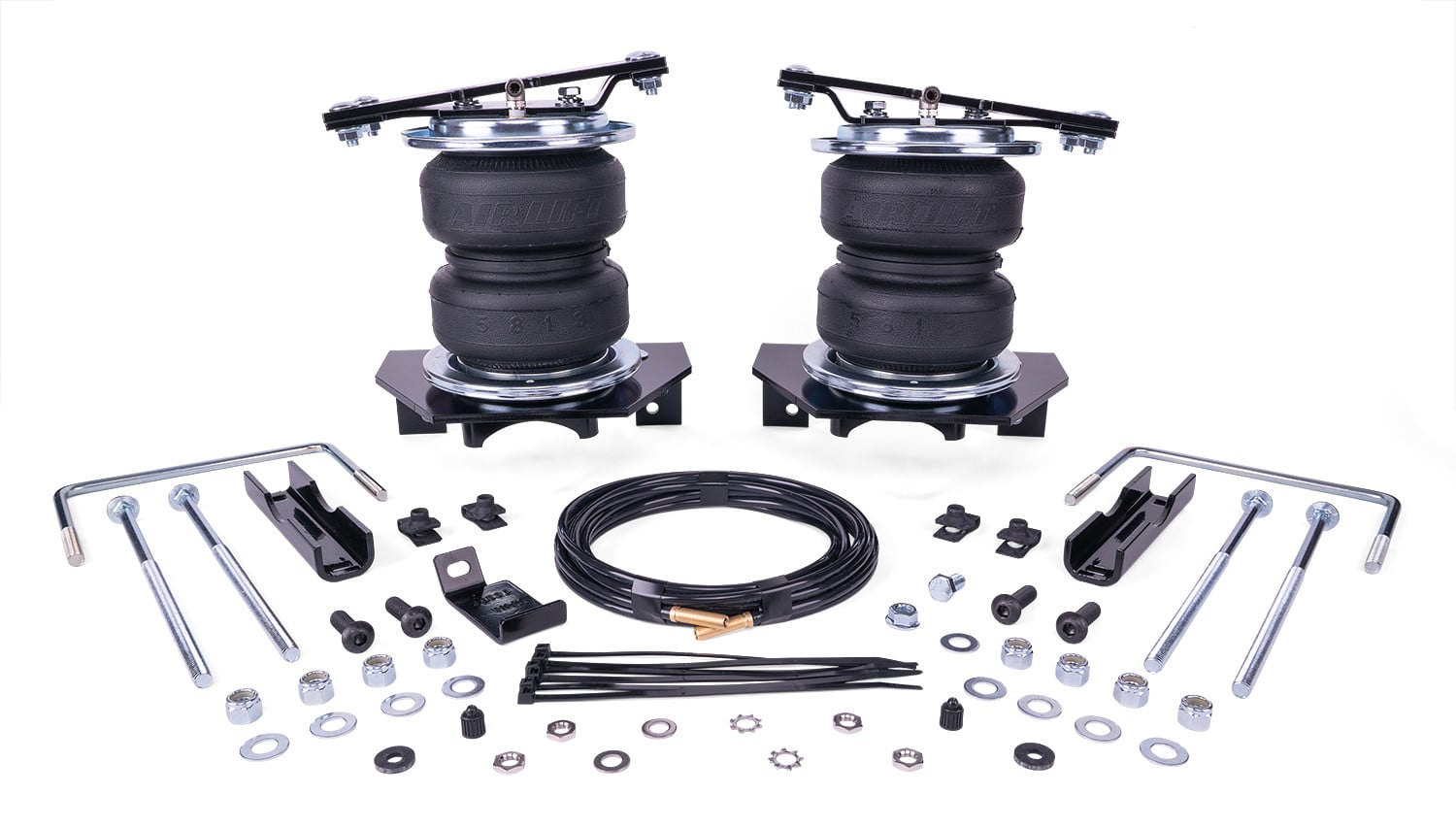
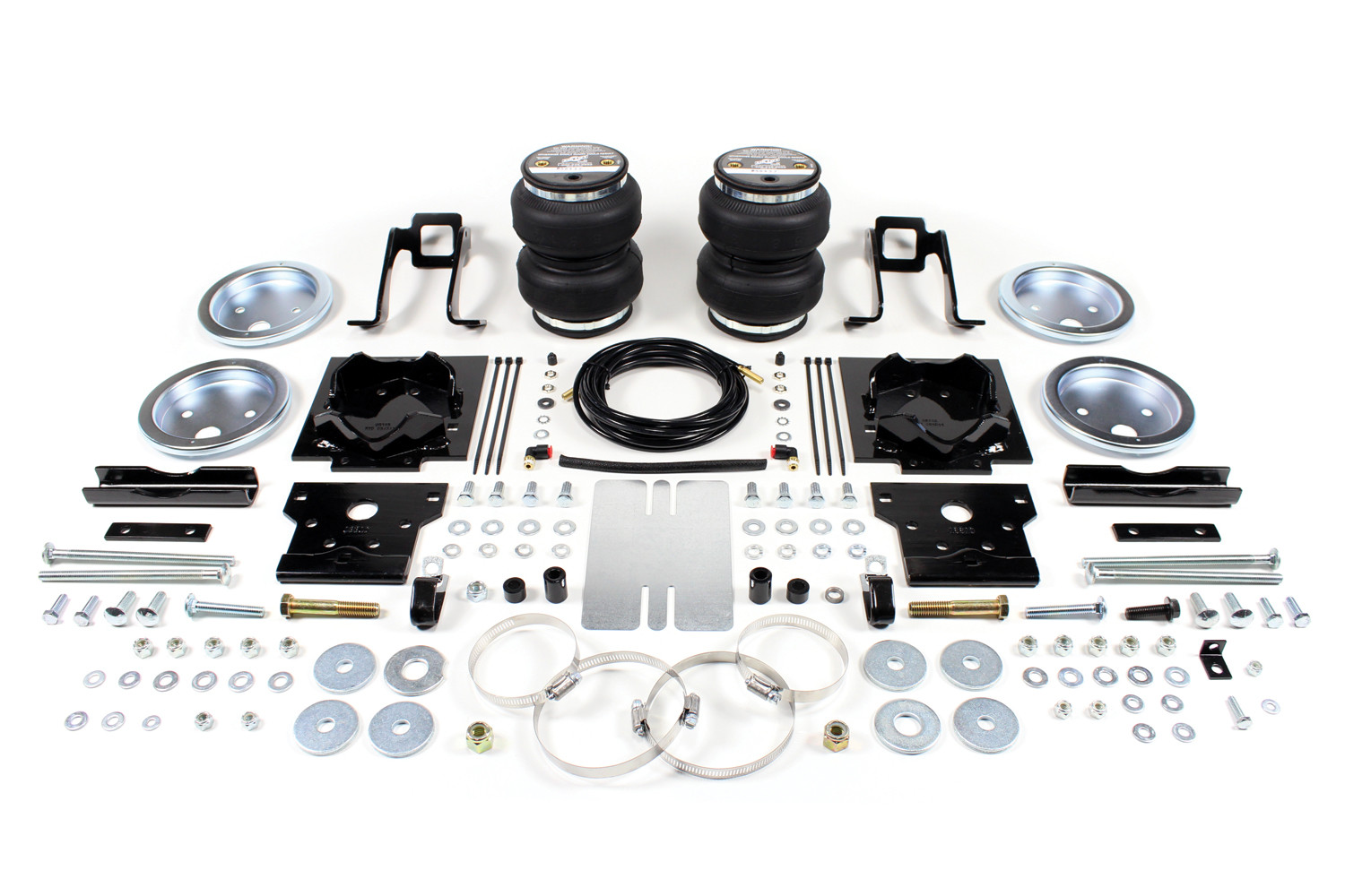
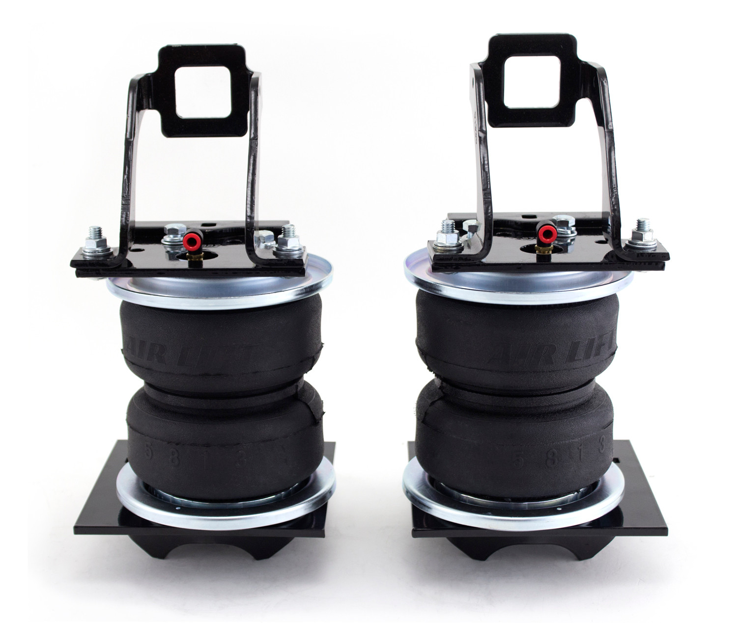
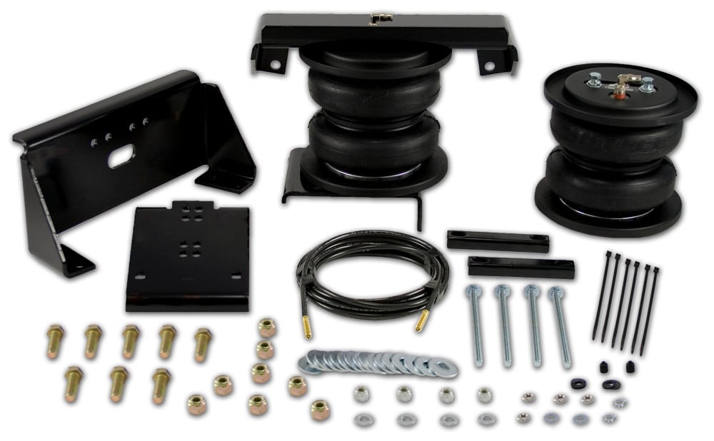
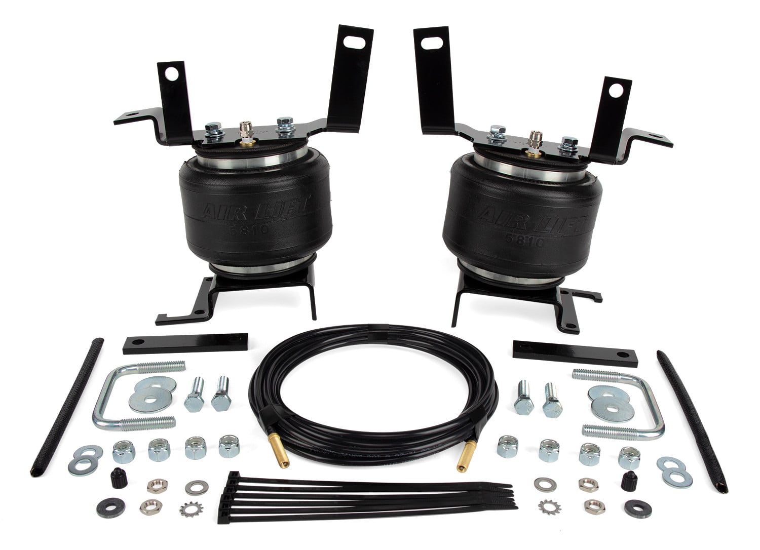
LoadLifter 5000 Leaf Spring Leveling Kit.

Air Lift adjustable air helper springs level your load, and give your truck, van, or SUV a safer, more comfortable ride. Air springs are easy to install between your existing springs and the vehicle frame. Just add air when towing or hauling a heavy load, and reduce air pressure when unloaded, they are fully adjustable for a great ride. Air Lift air springs eliminate sag, sway, and bottoming out. They are made with rugged, durable components for long, reliable service. LoadLifter 5000 kits are Air Lift's heaviest-rated kits for hauling or towing heavy loads. They have up to 5,000 pounds of leveling capacity, right up to the manufacturer's recommended Gross Vehicle Weight Rating, and are air adjustable from 5 to 100 PSI. LoadLifter 5000 kits fit such popular vehicles as ton and one-ton pickup trucks, many Class A, B & C motor homes, and commercial trucks and other severe uses. They also come standard with a limited lifetime warranty and an exclusive 60 day ride satisfaction guarantee.
Air Lift Company has developed dependable air spring suspension products since our inception in 1949. Our original product, a rubber air spring inserted into a car’s factory coil spring, was created and patented in 1950. We’ve come a long way since 1949 and are proud to be a dedicated suspension specialist company.
Today, Air Lift load support products are sold worldwide and are engineered to fit over 540 vehicles. Our extensive product line offers air helper springs for trucks, RVs, SUVs, CUVs, and vans, as well as the most technologically advanced on-board air compressor systems for on-the-go air spring control.
Air Lift leads the industry in no-drill applications – kits that bolt onto your vehicle’s frame, speeding the installation process. Our teams work constantly to bring innovative products to you and upgrade existing products with the latest technology.
All of our efforts are spent ensuring your safety and comfort by designing, engineering, and manufacturing the highest quality suspension products. We are a family-owned business based in Lansing, Michigan, and make your family and cargo’s safety our top priority.
Experts available to answer your questions
Call 888-634-9494Limited Lifetime
2 compatible vehicles
| Year | Make & Model | Notes |
|---|---|---|
| 1999 - 2004 | Ford F-250 Super Duty | Does not fit cab & chassis applications |
| 1999 - 2004 | Ford F-350 Super Duty | Does not fit cab & chassis applications |
The Air Lift LOADLIFTER 5000 57393 (Part #BBCG57393) fits 1999-2004 Ford F-250 Super Duty models. The 2004 model year is the last year covered by this part number. For newer models, check for an updated version.
Yes, the Air Lift LOADLIFTER 5000 57393 (Part #BBCG57393) is designed to fit the 1999-2004 Ford F-250 Super Duty.
The Air Lift LOADLIFTER 5000 57393 (Part #BBCG57393) fits the following vehicles: 1999-2004 Ford F-250 Super Duty; 1999-2004 Ford F-350 Super Duty. Always verify your specific year, make, and model before ordering.
The Air Lift LOADLIFTER 5000 57393 (Part #BBCG57393) Refer to the included instructions for installation details. Basic hand tools are typically all you need.
Yes, the LoadLifter 5000 Kit 57393 (MN-777) is designed for Ford F-250/F-350 (Single and Dual Rear Wheel) 2WD models. However, F-250 and F-350 models have different axle diameters: F-250 models typically have a 3.5-inch diameter axle and do not require an adapter, while F-350 models typically have a 4-inch diameter axle and require an adapter bracket (part 11951) to mount correctly between the stock U-bolts.
Yes, but modifications are required. If you have a fifth wheel hitch, you must remove the 3/4-inch hardware that bolts the side bracket to the outside of the frame above the axle. Depending on your hitch model, you may need to drill a 1/2-inch hole through the hitch plate to accommodate the new upper brace mounting. Some hitch models have a spacer between the bracket and frame rail that must be reinstalled. The manual provides three different installation paths depending on your specific hitch configuration.
The emergency brake cable on the right side of the vehicle must be modified for proper installation. For F-250 models or cables secured with a wire bracket, bend the bracket forward and down to move the cable clear of the lower bracket. For F-350 models or cables secured differently, remove the wire cable holder from the sway bar bracket and the top bolt holding the sway bar strap, then attach the emergency brake cable clamp (part 10181) using the M10 flange bolt supplied. The driver side emergency brake cable also requires a clamp attachment to the forward brace.
Required tools include: 7/16-inch and 9/16-inch open-end or box wrenches, adjustable wrench, ratchet with 3/8-inch, 9/16-inch, and 1/2-inch deep well sockets, 5/16-inch drill bits (very sharp), DIE grinder, hacksaw, heavy-duty drill, torque wrench, standard/metric/SAE sockets and wrenches, hose cutter or sharp knife, hoist or floor jacks, two safety stands, safety glasses, air compressor or compressed air source, and spray bottle with dish soap/water solution.
Most fasteners are included, but the 3/4-inch hardware used to attach the upper brace to the frame is supplied by the fifth wheel hitch manufacturer if you have one installed. If no hardware is supplied by the hitch manufacturer, use the 1/2-inch hardware supplied with the kit instead. The kit includes all other bolts, washers, nuts, and spacers needed for installation.
Yes, the jounce bumpers must be removed from under the frame over the axle as part of the installation process. After installation, the upper bracket will rest on a spacer (Z1 or Z2) and the stock jounce bumper bracket that remains riveted to the frame. Two different spacer lengths are supplied to ensure proper fit depending on your truck model.
The manual does not specify that the battery must be disconnected. However, it does note that you may need to disconnect the wiring harness from the driver side frame rail to gain clearance for the upper bracket during installation.
Drilling may be required depending on your vehicle configuration. If you have a fifth wheel hitch with a bracket plate running alongside the frame that does not have existing attaching hardware on the side where the frame slot is located, you must drill a 1/2-inch hole through the hitch plate using the slot in the frame as a template. Additionally, you must drill a 5/16-inch (8mm) hole for each Schrader valve location you choose for the air line system.
For F-250 models, the emergency brake cable modification is minimal. Simply bend the wire bracket forward and down at the same time. This moves the cable forward and down, clearing the bottom of the lower bracket. No cutting or permanent modification is required.
Yes, F-350 models require more extensive modification. Remove the wire cable holder from the side of the sway bar bracket attached to the axle and remove the top bolt holding the sway bar strap (discard both). Attach the emergency brake cable clamp (part 10181) to the brake cable and attach the frame clamp to the top sway bar hole using the M10 flange bolt (part N) supplied. Tighten securely.
The two 3/8-inch carriage bolts (M) that attach the clamp bar (D) to the lower bracket must be torqued to 16 lb-ft. Both nuts should be tightened evenly. After tightening, the upper and lower brackets may not appear parallel, which is a normal condition due to how the brackets mount.
The maximum air pressure is 100 PSI (7 BAR). The minimum recommended air pressure is 5 PSI (0.34 BAR). The actual air pressure needed depends on the load and your vehicle's gross vehicle weight rating. Never inflate beyond 100 PSI, and do not exceed your vehicle's maximum GVWR or payload rating.
The LoadLifter 5000 provides up to 5,000 pounds (2,268 kg) of load-leveling support with air adjustability from 5 to 100 PSI (0.34 to 7 BAR). The air springs are manufactured with reinforced, commercial-grade single or double convolute bellows with layers of rubber and cords that control growth.
The manual provides three recommended locations for the Schrader valves: (A) inside the fuel tank filler door, (B) inside rear wheel wells, or (C) license plate or rear bumper area. You must drill a 5/16-inch (8mm) hole at your chosen location. Make clean, square cuts with a razor blade or hose cutter when cutting the air line; do not use scissors or wire cutters.
Use zip ties to secure the air line to fixed points along the chassis. Keep at least 6 inches of clearance between all air lines and the exhaust system. Avoid sharp bends and edges. Do not pinch or kink the air line. Leave at least 2 inches of slack in the air line to allow for movement that might pull on it. The minimum bend radius for the air line is 1 inch (25mm).
Raise the vehicle and support the axle with safety stands, setting the stands as wide as possible on the axle. Wear safety glasses during installation. Do not pinch wiring or emissions lines inside the left frame rail when installing the assemblies. Ensure at least 6 inches of clearance between all air lines and the exhaust system. Make clean cuts with a razor blade or hose cutter when cutting air lines, not scissors or wire cutters.
Perform the following checks in order: (1) Clearance test—inflate air springs to 40-60 PSI and verify at least 1/2-inch clearance from tires, brakes, frame, shock absorbers, and brake cables. (2) Leak test—inflate to 40-60 PSI and check all connections for leaks; all leaks must be eliminated before road testing. (3) Heat test—ensure at least 6 inches clearance from heat sources; install heat shield if included. (4) Fastener test—after 500 miles, recheck all bolts for proper torque. (5) Road test—drive 10 miles and recheck clearance, fasteners, and air leaks.
A heat shield is required if the air springs or air lines are within 6 inches of heat sources such as the exhaust system. If a heat shield kit (part MM) is included in your kit, install it. The kit includes a metal heat shield, air line thermal sleeve, and four hose clamps. Attach the metal heat shield to the exhaust using hose clamps where it is closest to the air spring, and slide the air line thermal sleeve over the air line where it is closest to the exhaust. Maintain at least 1/2 inch of dead air space between the shield and exhaust. If a heat shield is required but not included, contact Air Lift customer service at (800) 248-0892.
Check air pressure weekly. Always maintain normal ride height and never inflate beyond 100 PSI (7 BAR). If the system develops an air leak, use a soapy water solution to check all air line connections and the inflation valve core before deflating and removing the air spring.
Check air pressure weekly. After 500 miles of driving, recheck all bolts for proper torque. After the initial 10-mile road test, continue to monitor for clearance, loose fasteners, and air leaks. Always maintain normal ride height and never exceed 100 PSI inflation pressure or your vehicle's GVWR or payload rating.
Yes, it fits both F-250 and F-350 (Single and Dual Rear Wheel) 2WD models. F-350 models require an adapter bracket due to their larger 4-inch axle diameter, while F-250 models with 3.5-inch axles do not.
You need a heavy-duty drill, DIE grinder, hacksaw, torque wrench, ratchet with sockets, wrenches, safety stands, hoist or floor jacks, safety glasses, air compressor, and a hose cutter or sharp knife.
Maximum pressure is 100 PSI (7 BAR); minimum is 5 PSI (0.34 BAR). Do not exceed your vehicle's GVWR or payload rating.
Keep at least 6 inches of clearance between all air lines and the exhaust system. Install the heat shield if air springs are within 6 inches of heat sources.
Perform a clearance test (1/2-inch minimum from tires, brakes, frame, shocks, cables), leak test at 40-60 PSI, heat test (6-inch minimum from heat sources), and recheck fasteners after 500 miles.
Check air pressure weekly. Recheck all bolts for proper torque after 500 miles of driving.
Use a soapy water solution to check all air line connections and the inflation valve core to locate the leak. All leaks must be eliminated before the vehicle is road-tested. If the leak is at a connection, tighten the fitting. If the leak persists or is at the valve core, deflate and remove the air spring and contact Air Lift customer service at (800) 248-0892.
This is a normal condition. Once the clamp bar bolts are tightened to 16 lb-ft, the upper and lower brackets may not be parallel and may look out of alignment. This is expected because of the way the lower bracket and upper bracket mount, and there may be some variance in models. This condition is considered normal and does not indicate an installation problem.
Inflate the air springs to 40-60 PSI and verify at least 1/2-inch clearance from tires, brakes, frame, shock absorbers, and brake cables. If clearance is insufficient, the installation may not be correct. Review the positioning of the assemblies on the axle and ensure the spacers (Z1 or Z2) are properly seated in the jounce bumper bracket holes. If clearance issues persist, contact Air Lift customer service at (800) 248-0892.
On Sale Today
Original price was $692.99. Current price is $502.99.You save $190.00 (27%)
Free Shipping
Ships free on all orders
 Authorized Dealer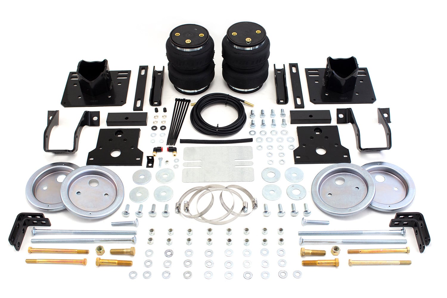

Quick Ship
In stock and ready to ship — order now!
FREE ShippingFREE SHIPPING
Estimated delivery Wed, Sep 23 - Sat, Sep 26
Order before 2 PM EST Monday–Friday for same-day processing
Guaranteed safe & secure checkout
No reviews have been added for this product.