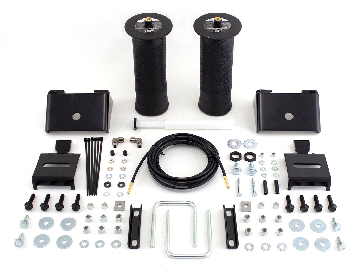
Air Lift RIDE CONTROL KIT 59501Air LiftOriginal price was $590.99. Current price is $428.99.In Stock
View productOur in-house experts typically reply within one business day.

Air Lift
Verify Fitment
Select your vehicle to confirm this part fits.
2015 - 2020 Ford F-150
Confirmed to Fit
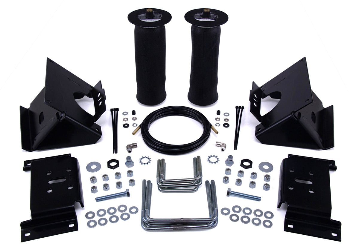


Always the correct part
We know our products
Quality Products
Free Shipping!
Always the correct part
We know our products
Quality Products
Free Shipping!
Air Lift RideControl air helper springs are air-adjustable from 5 to 100 PSI and have up to 2,000 pounds of leveling capacity, right up to the manufacturer's recommended Gross Vehicle Weight Rating.

RideControl provides more safety, stability and ride comfort. The kit fits many popular vehicles with leaf springs, including half-ton and mini pickups, full-size and mini vans, and SUVs. Both front and rear applications are available for these vehicles. Each kit includes everything you need, and is easily installed in two hours or less. End caps are made of an ultra-strong nylon composite that is as strong as steel, but weighs less and is corrosion-proof. Air Lift RideControl adjustable air springs work with your existing leaf spring suspension. Just add air when towing or hauling a heavy load, and reduce air pressure when unloaded, the air bags are fully adjustable for a great ride. Air Lift air springs eliminate sag, sway, and bottoming out. Each kit includes everything you need, and is easily installed in two hours or less. End caps are made of an ultra-strong nylon composite that is as strong as steel, but weighs less than steel and is also corrosion-proof. These rugged, durable components mean that you get reliable service from the springs for the lifetime of the vehicle. Air Lift RideControl air helper springs are air-adjustable from 5 to 100 PSI and have up to 2,000 pounds of leveling capacity, right up to the manufacturer's recommended Gross Vehicle Weight Rating. They also come with a limited lifetime warranty and an exclusive 60-day ride satisfaction guarantee.
Air Lift Company has developed dependable air spring suspension products since our inception in 1949. Our original product, a rubber air spring inserted into a car’s factory coil spring, was created and patented in 1950. We’ve come a long way since 1949 and are proud to be a dedicated suspension specialist company.
Today, Air Lift load support products are sold worldwide and are engineered to fit over 540 vehicles. Our extensive product line offers air helper springs for trucks, RVs, SUVs, CUVs, and vans, as well as the most technologically advanced on-board air compressor systems for on-the-go air spring control.
Air Lift leads the industry in no-drill applications – kits that bolt onto your vehicle’s frame, speeding the installation process. Our teams work constantly to bring innovative products to you and upgrade existing products with the latest technology.
All of our efforts are spent ensuring your safety and comfort by designing, engineering, and manufacturing the highest quality suspension products. We are a family-owned business based in Lansing, Michigan, and make your family and cargo’s safety our top priority.
Experts available to answer your questions
Call 888-634-9494Limited Lifetime
1 compatible vehicles
| Year | Make & Model | Notes |
|---|---|---|
| 2015 - 2020 | Ford F-150 | Does not fit Raptor models Does not fit vehicles with in: bed hitch |
The Air Lift RIDE CONTROL KIT 59570 (Part #BBCG59570) fits the following vehicles: 2015-2020 Ford F-150. Always verify your specific year, make, and model before ordering.
The Air Lift RIDE CONTROL KIT 59570 (Part #BBCG59570) fits 2015-2020 Ford F-150 models. The 2020 model year is the last year covered by this part number. For newer models, check for an updated version.
Yes, the Air Lift RIDE CONTROL KIT 59570 (Part #BBCG59570) is designed to fit the 2015-2020 Ford F-150.
The Air Lift RIDE CONTROL KIT 59570 (Part #BBCG59570) Refer to the included instructions for installation details. Basic hand tools are typically all you need.
The RideControl kit is an air spring suspension system for the Ford F-150 that provides load-leveling support. It uses two sleeve-style air bags, each rated at a maximum of 100 PSI, that can provide up to 2,000 pounds of combined load-leveling support. The air springs are designed like tires with layers of rubber and cords to control expansion. The system does not alter the vehicle's GVWR or payload capacity.
The manual states the kit is designed for the Ford F-150 but does not specify which model years, cab styles (Regular, SuperCab, SuperCrew), or bed lengths are compatible. Contact Air Lift customer service at (800) 248-0892 to confirm fitment for your specific F-150 before purchasing.
Required tools include: hoist or floor jack, two safety stands, safety glasses, torque wrench, standard open-end combo wrenches, medium adjustable wrench, ratchet, metric and standard sockets, 5/16" drill bit (very sharp), heavy-duty drill, bench or hand grinder, black spray paint, hose cutter or sharp knife, air compressor or compressed air source, and spray bottle with dish soap/water solution.
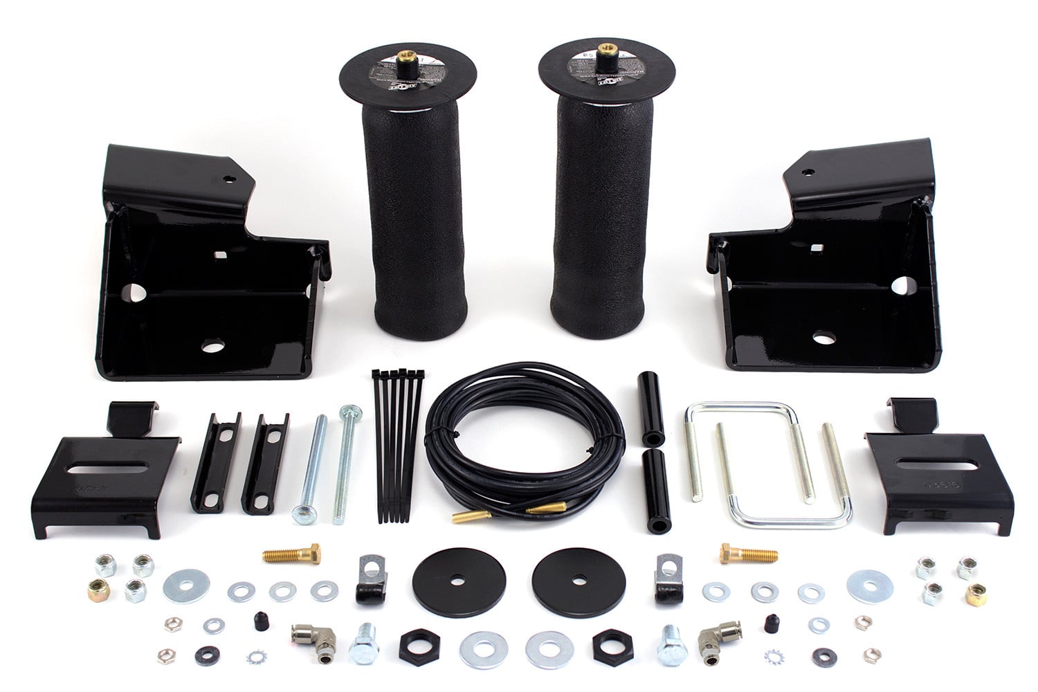
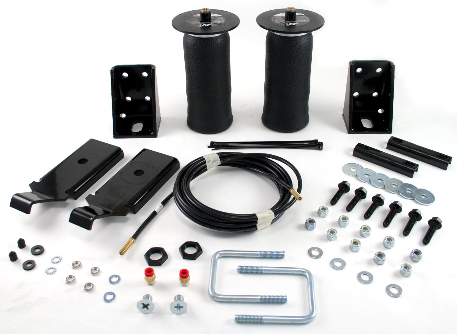
The kit includes: two upper brackets (left A1 part 07170, right A2 part 07474), two lower brackets (B, part 03008), two air springs (C, part 58571), four frame U-bolts (D, part 10787), four lower bracket U-bolts (E, part 10975), two 1/2"-3 X 7/8" hex head cap screws (F, part 17124), two M10-1.50 X 70 tap bolts (G, part 21837), two 1/2" flat washers (H, part 18414), sixteen 3/8"-16 nylon lock nuts (I, part 18435), eighteen 3/8" flat washers (J, part 18444), two 3/4" serrated lock washers (K, part 18450), two 3/4"-16 nylon jam nuts (L, part 18454), two 90° swivel fittings (M, part 21837), one air line assembly (AA, part 20086), six tie straps (BB, part 10466), two valve caps (CC, part 21230), two 5/16" flat washers (DD, part 18501), two rubber washers (EE, part 21234), two star washers (FF, part 18411), and four 5/16" hex nuts (GG, part 21233).
Yes. The first step is to jack up the vehicle and support the axle with safety stands, then remove the rear wheels to access the jounce bumpers and frame mounting points.
Yes. The jounce bumpers must be unbolted and removed during installation. They will be reinstalled later as part of the upper bracket assembly.
1. Jack the vehicle and support the axle with safety stands; remove rear wheels. 2. Remove the jounce bumpers. 3. Set the frame U-bolts (D) around the frame from inside-out on both sides, ahead of and behind the jounce bumper mounting location, ensuring they do not pinch brake lines or wiring. 4. Position the left (A1) and right (A2) upper brackets against the frame, aligning the U-bolts through the bracket mounting holes. 5. Cap the U-bolts with 3/8" flat washers (J) and 3/8" nylon lock nuts (I); leave loose. 6. Grind the outside flange of the jounce bumper cup flush with the rest of the cup and spray with black paint. 7. Insert the M-10 tap bolt (G) through a flat washer (J) and through the jounce bumper, then install back onto the bottom frame flange; tighten just until the bracket touches the frame. 8. Torque the frame U-bolts evenly to 10 lb.-ft. (14 Nm), then torque the jounce bumper bolt to 30 lb.-ft. (41 Nm). Repeat for the opposite side.
Yes. To make sufficient clearance for the flex member (rubber part) on the air spring, the outside edge of the jounce bumper cup (steel portion) must be ground flush with the rest of the cup on both sides. After grinding, spray the bare metal surface with black paint.
Yes. You must drill two 5/16" holes to install the inflation valves. Choose a convenient location such as the wheel well flanges, license plate recess in bumper, under the gas cap access door, or through the license plate. Ensure there is enough clearance around the inflation valves for an air chuck.
1. Install the 90° swivel fitting (M) onto the top port of each air spring (C) finger-tight plus 1-1/2 turns. 2. Install each air spring to the lower brackets (B) using the 1/2" bolt (F) and flat washer (H); leave loose. 3. Set the assemblies onto the leaf spring, ensuring the upper fitting and thread post go through the slot in the upper bracket and the flange on the lower bracket points outward (tire-side). 4. Set the lower bracket U-bolts (E) under the leaf springs through the holes in the lower bracket and cap with 3/8" flat washers (J) and 3/8" nylon lock nuts (I); torque to finger-tight only. 5. Install the upper air spring hardware by setting the 3/4" serrated lock washer (K) over the fitting and thread post, then thread the 3/4" nylon lock jam nut (L) onto the post; torque to finger-tight only.
1. Choose a convenient location (wheel well flanges, license plate recess, under gas cap, or through license plate) with enough clearance for an air chuck. 2. Drill two 5/16" holes. 3. Cut the air line assembly in two equal lengths. 4. Place a 5/16" nut and star washer on the air valve, leaving approximately 1/2" of valve exposed after installation for a pressure gauge or air chuck. 5. Push the inflation valve through the hole and secure with a rubber washer, flat washer, and another 5/16" nut; tighten to secure.
Route the air line along the frame to the air fitting on the air spring. Maintain at least 6" of clearance between the air line and heat sources such as exhaust pipes, muffler, or catalytic converter. Avoid sharp bends and edges. Use plastic tie straps to secure the air line to fixed points along the chassis; keep tie straps tight but do not pinch the air line. Leave at least 2" of slack to allow for movement that might pull on the air line.
Use a sharp knife or hose cutter to make clean, square cuts; do not use scissors or wire cutters as these may deform the line and cause leaks. Do not cut at an angle. Leave approximately 12" of extra air line. Insert the air line into the 90-degree swivel fitting by pushing it in until it bottoms out; 9/16" of air line should be in the fitting. Inspect the hose for lengthwise scratches before installation; contact Air Lift customer service at (800) 248-0892 if damaged.
1. Inflate the air spring to 5 PSI only. 2. Adjust the spring to be perpendicular to both top and bottom brackets using the slots in the mounts; pinch the flex member at the bottom around the piston to check for symmetrical air cushion. 3. Mark the location of the bottom piston relative to the lower bracket, deflate, and raise the inside of the lower bracket to slip a 3/4" wrench onto the 1/2" bolt; tighten to no more than 15 lb.-ft. (20 Nm). 4. Inflate back to 5 PSI and readjust the upper spring forward or back in the slot if necessary; tighten the nylon jam nut to no more than 4 lb.-ft. (5 Nm) using a medium adjustable wrench or open-end wrench. 5. Torque the lower mounting hardware on the lower bracket U-bolts to 15 lb.-ft. (20 Nm) on both sides. 6. Install the tires and torque to manufacturer specifications.
Frame U-bolts (D): 10 lb.-ft. (14 Nm). Jounce bumper bolt (G): 30 lb.-ft. (41 Nm). Lower spring-to-bracket bolt (F): no more than 15 lb.-ft. (20 Nm). Upper nylon jam nut (L): no more than 4 lb.-ft. (5 Nm) (just snug). Lower bracket U-bolts (E): 15 lb.-ft. (20 Nm). Tire torque: manufacturer specifications.
The maximum air pressure is 100 PSI. Each air spring is rated at a maximum of 100 PSI. Never inflate beyond 100 PSI.
The minimum recommended pressure is 5 PSI. The system can safely be run at zero air pressure, but operating below the minimum air spring pressure of 5 PSI will void the Air Lift warranty.
No. The installation of the RideControl kit does not alter the gross vehicle weight rating (GVWR) or payload of the vehicle. You must check the vehicle owner's manual and not exceed the maximum load listed for the vehicle. Exceeding the GVWR is dangerous and voids the Air Lift warranty.
Loaded vehicles require at least 25 PSI. A "loaded vehicle" refers to a vehicle with a heavy bed load, a trailer, or both. The springs support approximately 40 pounds of load (combined on both springs) for each 1 PSI of pressure. The required air pressure varies depending on the state of the original suspension and the load location. Loads carried behind the axle (including tongue loads) require more leveling force (pressure) than those carried directly over the axle. Never exceed GVWR regardless of air spring pressure or other load assist.
1. Inflate the air spring to 30 PSI. 2. Spray all connections and inflation valves with a solution of 1/5 liquid dish soap and 4/5 water. Spot leaks by looking for bubbles in the soapy water. 3. After testing, deflate the springs to the minimum pressure required to restore normal ride height; do not deflate below 5 PSI. 4. Check air pressure again after 24 hours. A 2-4 PSI loss after initial installation is normal. Retest for leaks if the loss is more than 5 PSI.
1. Clearance test: Inflate air springs to 75-90 PSI and verify at least 1/2" clearance from anything that might rub (tire, brakes, frame, shock absorbers, brake cables). 2. Leak test: Inflate to 75-90 PSI and check all connections for leaks; all leaks must be eliminated before road testing. 3. Heat test: Ensure at least 6" clearance from heat sources (exhaust, muffler, catalytic converter); install a heat shield if included or if required. 4. Fastener test: Recheck all bolts for proper torque. 5. Road test: Drive 10 miles and recheck for clearance, loose fasteners, and air leaks.
Check air pressure weekly. Also recheck the system after 30 days or 500 miles, whichever comes first, to ensure all fasteners are tight and there are no signs of rubbing or abrasion.
1. Check air pressure weekly. 2. Always maintain normal ride height; never inflate beyond 100 PSI. 3. If an air leak develops, use a soapy water solution (1/5 liquid dish soap and 4/5 water) to check all air line connections and the inflation valve core before deflating. 4. Loaded vehicles require at least 25 PSI. 5. When increasing load, adjust air pressure to maintain normal ride height. 6. Always add air in small quantities, checking pressure frequently. 7. When raising the vehicle by the frame, ensure the system is at minimum pressure (5 PSI) to reduce tension on suspension/brake components. 8. Periodically check fasteners for tightness and air springs for signs of rubbing; realign if necessary. 9. Periodically spray the air springs with a garden hose to remove mud, sand, gravel, or other debris.
One of the air lines may be improperly installed or may have a hole or crack. Start by leak testing the air line connections using a soapy water solution. If no leaks are found, look for leaks in the rest of the air lines. Follow the steps in the "Fixing Leaks" section of the manual.
Look for a kink or fold in the air line going to that air spring. Replace any line that has been kinked.
1. Check the air line connection by deflating the spring and removing the line by pulling the collar against the fitting and pulling firmly on the air line. Trim 1" off the end of the air line with a clean, square cut. Reinsert the air line into the push-to-connect fitting. 2. If still leaking, check the threaded connection by tightening the swivel fitting another half turn. If it still leaks, deflate the air spring, remove the fitting, re-coat the threads with thread sealant, and reinstall by hand tightening as much as possible, then use a wrench for an additional two turns.
1. Check the valve core by tightening it with a valve core tool. 2. Check the air line by removing it from the barbed fitting. Cut the air line off a few inches in front of the fitting and use pliers or vice grips to pull/twist the air line off the fitting. Do not cut off the air line completely as this will nick the barb and render the fitting useless. If these steps do not resolve the problem, call Air Lift customer service at (800) 248-0892.
The kit is designed for the Ford F-150, but the manual does not specify which model years, cab styles, or bed lengths are compatible. Contact Air Lift customer service at (800) 248-0892 to confirm fitment before purchasing.
You need a hoist or floor jack, safety stands, torque wrench, wrenches, ratchet, sockets, 5/16" drill bit, heavy-duty drill, grinder, black spray paint, hose cutter or sharp knife, air compressor, and a spray bottle with soap/water solution.
Yes. You must drill two 5/16" holes for the inflation valves. You must also grind the outside edge of the jounce bumper cup flush with the rest of the cup on both sides.
No. The kit does not alter the GVWR or payload. You must not exceed the maximum load listed in your vehicle owner's manual.
Frame U-bolts (D) must be torqued evenly to 10 lb.-ft. (14 Nm).
The jounce bumper bolt (G) must be torqued to 30 lb.-ft. (41 Nm) after the frame U-bolts are torqued to 10 lb.-ft. (14 Nm).
Cause: One of the air lines may be improperly installed or may have a hole or crack. Fix: Start by leak testing the air line connections using a soapy water solution (1/5 dish soap and 4/5 water). If no leaks are found, look for leaks in the rest of the air lines and follow the steps in the "Fixing Leaks" section of the manual.
Cause: A kink or fold in the air line going to that air spring. Fix: Replace any line that has been kinked.
1. Check the air line connection: deflate the spring, remove the line by pulling the collar and pulling firmly, trim 1" off the end with a clean square cut, and reinsert into the fitting. 2. If still leaking, tighten the swivel fitting another half turn. 3. If still leaking, deflate, remove the fitting, re-coat the threads with thread sealant, and reinstall by hand tightening as much as possible, then use a wrench for an additional two turns.
1. Check the valve core by tightening it with a valve core tool. 2. Check the air line by removing it from the barbed fitting. Cut the air line a few inches in front of the fitting and use pliers or vice grips to pull/twist the line off. Do not cut the line completely as this will nick the barb and render the fitting useless. If the problem persists, call Air Lift customer service at (800) 248-0892.
On Sale Today
Original price was $590.99. Current price is $428.99.You save $162.00 (27%)
Free Shipping
Ships free on all orders
 Authorized Dealer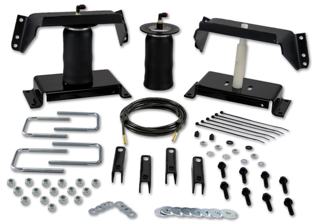

Quick Ship
In stock and ready to ship — order now!
FREE ShippingFREE SHIPPING
Estimated delivery Tue, Aug 25 - Fri, Aug 28
Order before 2 PM EST Monday–Friday for same-day processing
Guaranteed safe & secure checkout
No reviews have been added for this product.