
CURT 60665 Double Lock Gooseneck Installation Brackets, Fits Select Toyota TundraCURTOriginal price was $355.95. Current price is $216.63.Out of Stock
View productOur in-house experts typically reply within one business day.

CURT
Verify Fitment
Select your vehicle to confirm this part fits.


Always the correct part
We know our products
Quality Products
Free Shipping!
Always the correct part
We know our products
Quality Products
Free Shipping!
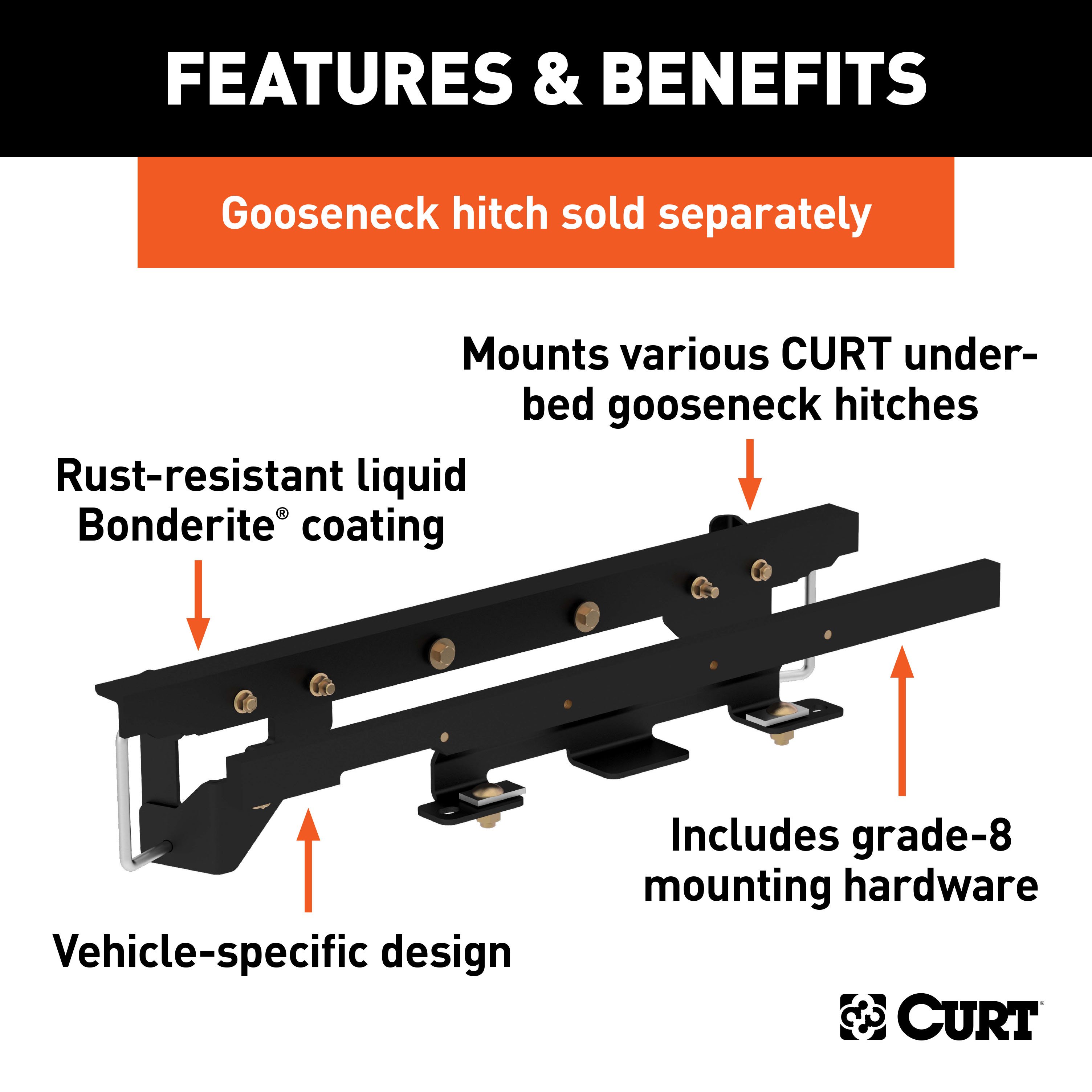
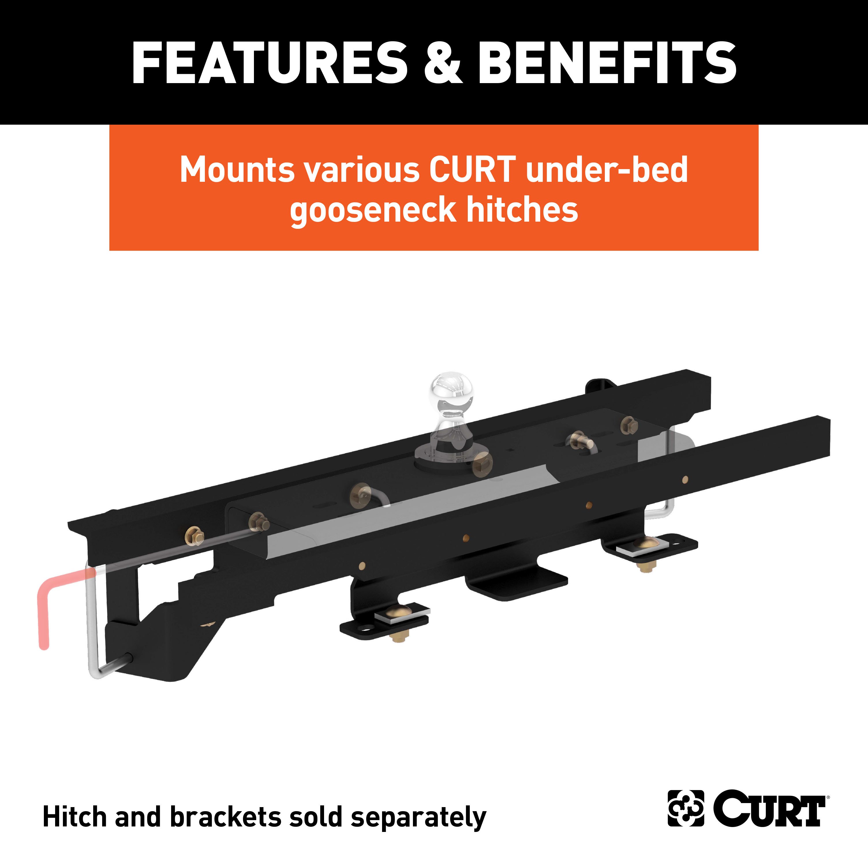
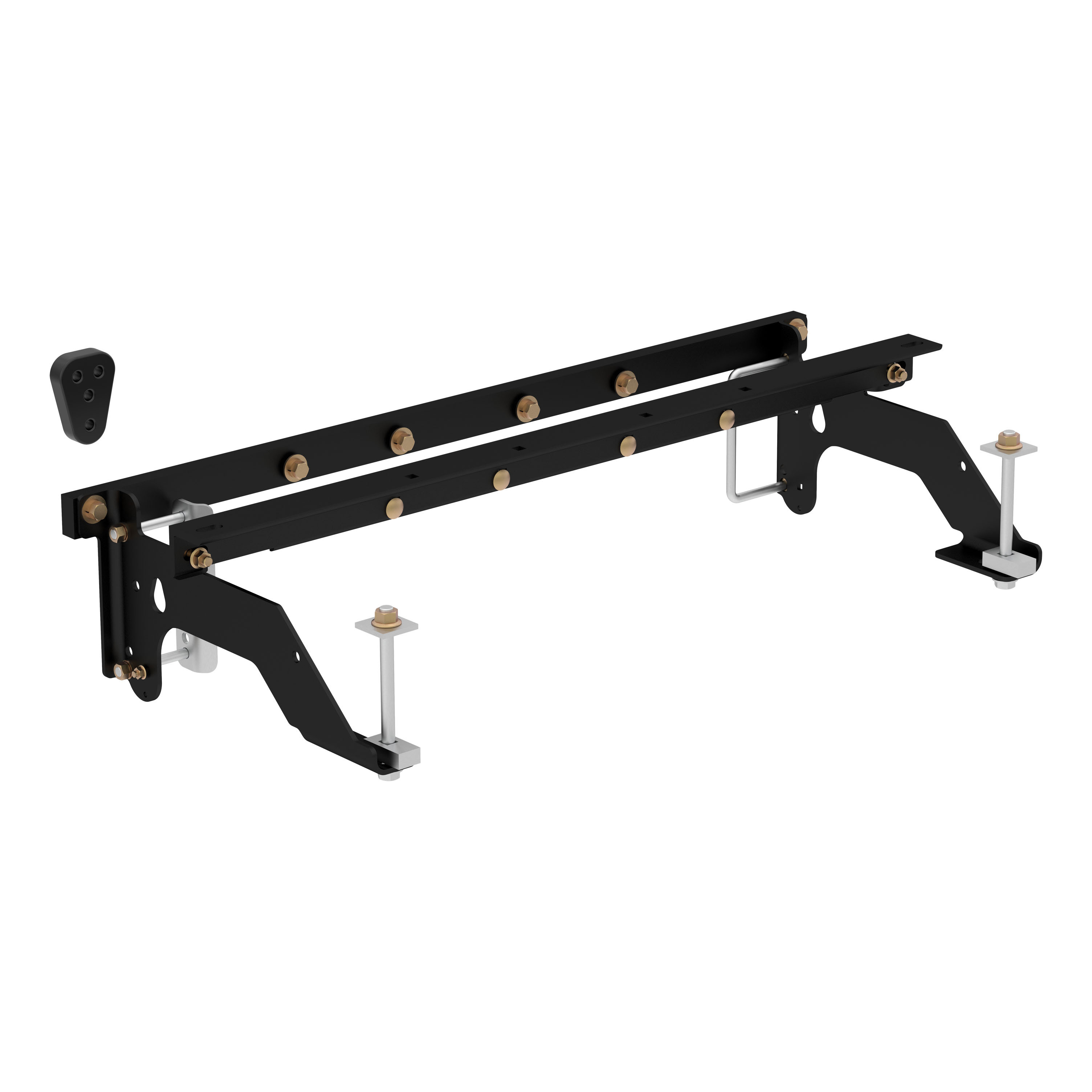
Includes mounting brackets only (gooseneck hitch sold separately)
Capacity limited to lowest-rated towing component

Includes mounting brackets only (gooseneck hitch sold separately)
Warranty: Limited Lifetime Warranty (One-Year Finish, One-Year Parts)
Finish: A-COAT
Installation Time Exact (Minutes): 0
Choosing the right gooseneck hitch is only half the battle in preparing your pickup truck for towing a gooseneck trailer. CURT gooseneck hitches are a premium option in the heavy-duty towing industry, but they are only one of the members in the heavyweight tag team that is CURT gooseneck towing. While a gooseneck hitch gets all the glory above the floor of your truck bed, gooseneck installation brackets provide sure footing and a solid foundation for that oversized gooseneck trailer. Gooseneck installation brackets work by bolting onto the frame of your truck, typically using pre-existing holes. With a set of brackets firmly bolted on, a gooseneck hitch is able to be attached and is given the strength it needs to manage the massive amount of weight of a gooseneck trailer. With so many gooseneck hitch options available from CURT, we wanted to make sure we offered the gooseneck installation products needed to give you a complete towing package. Our installation brackets fit multiple vehicles and hitch heads. This particular set of gooseneck installation brackets is able to work with certain CURT Double Lock gooseneck hitches. It is rated to the vehicle's maximum gross trailer weight capacity and provides a custom fit for certain years the Dodge Ram 1500 with air suspension (see application info to verify fitment). With each gooseneck installation bracket sub kit, we provide the necessary hardware for an easier installation, and we coat our gooseneck brackets in a liquid A-coat to make sure rust and other potential damages are not a problem.

CURT offers a variety of high-quality trailer hitches and accessories for select vehicle models. Find the perfect fit for your towing needs at TowUniverse.
CURT, a Lippert brand, offers a complete line of towing products and is the leading manufacturer of custom-fit trailer hitches. We offer the broadest selection of custom-fit hitches, and each one is designed, welded, and coated in Wisconsin.
CURT is also a leader in flat towing products, as well as 5th wheel, gooseneck, and weight distribution hitches, ball mounts, electrical components, cargo solutions, and other towing accessories.
For everything from passenger cars and vans to full-size pickups and SUVs, CURT is 'The First Name in Towing Products®.'

Experts available to answer your questions
Call 888-634-94941 compatible vehicles
| Year | Make & Model | Notes |
|---|---|---|
| 2013 - 2016 | Ram 1500 | No Drilling Required Air Ride Suspension |
The CURT 60658 Double Lock Gooseneck Installation Brackets, Fits Select Ram 1500 with Air Suspension (Part #BKDK60658) fits 2013-2016 Ram 1500 models. The 2016 model year is the last year covered by this part number. For newer models, check for an updated version.
The CURT 60658 Double Lock Gooseneck Installation Brackets, Fits Select Ram 1500 with Air Suspension (Part #BKDK60658) fits the following vehicles: 2013-2016 Ram 1500. Always verify your specific year, make, and model before ordering.
Yes, the CURT 60658 Double Lock Gooseneck Installation Brackets, Fits Select Ram 1500 with Air Suspension (Part #BKDK60658) is designed to fit the 2013-2016 Ram 1500.
The CURT 60658 Double Lock Gooseneck Installation Brackets, Fits Select Ram 1500 with Air Suspension (Part #BKDK60658) Drilling is not required for installation. Basic hand tools are typically all you need.
The Curt 60658 is designed for RAM 1500 trucks equipped with Active-Level air suspension. It fits bed lengths of 5'7", 6'4", and 8". Confirm your truck has the Active-Level air suspension system before purchasing. If you have a two-wheel drive model, you must verify that the inverted ball will not interfere with the top of the differential when loaded.
Yes, the Curt 60658 fits short bed RAM 1500 models (5'7" bed). However, you must check for adequate turning clearance between the front of all trailers and the truck cab, as short bed models have tighter clearance. Use the clearance calculation provided in the manual to verify your specific trailer will not interfere with the cab during turns.
Yes, the hitch is compatible with dual exhaust systems, but installation is more difficult. The manual includes specific instructions for dual exhaust models: the rear cross member notch provides clearance for the exhaust bracket, the driver side carriage bolt must be installed in the outermost hole to keep it away from the exhaust, and you may need to pry the exhaust downward while installing the flange nut on the driver side bolt.
The hitch can be installed on vehicles with factory air suspension, but you must not pinch the 2 air suspension lines on the passenger side. Use the 3 cable ties (CM-116415-CT) included in the parts list to hold the lines away from the gooseneck components during and after installation.
Required tools are: flat screwdriver, 3/4" and 15/16" wrenches, 3/4" and 15/16" sockets, ratchet, torque wrench, and adjustable wrench. For the pin handle installation, you will also need a rotary cutting tool or grinder to cut a 3/4" wide × 1" tall slot in the inner fender liner. A hole saw (4" diameter) or saber saw with metal cutting blade is needed to cut the truck bed hole.
The parts list includes: 2 × 5/8" fishwire tools, 2 × 1/2-13 × 2 1/4" hex bolts, 10 × 1/2-13 × 1 1/2" hex bolts, 10 × 1/2" lock washers, 12 × 12 mm flat washers, 12 × hex flange nuts (1/2-13), 2 × 1/2-13 × 4 1/8 × 6 × 1 1/2" square U-bolts (CM-1208-UBS), 2 × 5/8-11 × 1 1/2" carriage bolts, 2 × 0.250 × 1.25 × 2.50" square hole spacers (CM-SP9), 2 × 5/8-11 hex flange nuts, and 3 × 11/64" × 15" cable ties (CM-116415-CT).
No, the Curt 60606 Double Lock Gooseneck Install Tool is recommended but not required. It is used to lift and hold the center section of the hitch in place during installation, which may facilitate fastening the cross-member to the center section, especially if the truck bed floor has been distorted downward from heavy use. If you use it, it must be disconnected before squaring the center section across the frame, installing the sideplates, and torquing fasteners.
The manual does not specify whether battery disconnection is required. Contact Curt Manufacturing technical support at 1-877-287-8634 for clarification.
Before installation, you must relocate the wiring harness that runs along the top of the frame cross member just behind the axle. Pull the four plug fasteners securing it and push the harness toward the rear of the truck. Also remove the vent tube clip from the frame rail, allowing the vent tube to hang during installation. The vent tube will be relocated after the hitch is installed. Additionally, brake, fuel, and electrical lines may need to be loosened or repositioned to provide clearance for new hardware.
The distance depends on bed length: for 5'7" and 6'4" beds, measure 40-1/8" from the tailgate end of the truck bed; for 8' beds, measure 42-1/8". Hook the tape measure over the back of the truck box and measure from the tailgate end—do not measure from the edge of the tailgate. Also mark the center between the wheel wells. The hole location should be in the center of a low rib in the bed floor. Measure, mark, and saw carefully, as this hole is critical to correct installation.
Make a 4" diameter hole at the marked location using either a 4" hole saw or by marking a 4" circle and cutting it out with a saber saw equipped with a metal cutting blade. If the truck has a plastic bed liner, you may drill through both, but it is more difficult to accurately locate the midpoint between the wheel wells and to keep the bed liner from moving while cutting the hole.
The installation sequence is: 1) Mark and cut the 4" hole in the truck bed; 2) Install the rear cross member; 3) Install the center section; 4) Install the front cross member; 5) Install the side plates; 6) Install the rear brace; 7) Tighten all hardware in the specified sequence; 8) Relocate the axle vent tube; 9) Install safety chain u-bolts; 10) Install the pin handle. Hand tighten all connections initially, then tighten in the specified sequence after ensuring the center section is tight against the truck bed and the hitch is centered and square.
The rear cross member (2" × 1" bar with threaded holes) is installed from the passenger side, just in front of the rear tire. Insert it between the frame and the top suspension control arm with the notch machined into the cross member going first and facing the rear. Slide the leading end above the exhaust and over the frame on the driver side while moving toward the rear. Raise the opposite end until both ends are positioned over the top of the frame with the cross member laying flat and the notch still facing the rear. Adjust so it is parallel to the axle and slide it toward the rear until it is over the frame cross member where the wiring harness was attached. Rotate the cross member from flat to vertical so the notch on the driver side is down. Slide it rearward as far as possible while ensuring the wiring harness does not get pinched. The cross member will rest on the frame and should be suspended just above the frame cross member.
Position the center section so the 4" diameter raised area fits into the 4" hole in the truck bed. The round receiver will be almost directly above the axle. From behind the rear axle with the bottom side of the center section facing the passenger side, send the end without the spring over the axle first. Send the lead end toward the front of the truck and to the passenger side far enough so the rear end clears the exhaust. Once clear of the exhaust, rotate and lift so the 4" raised area is toward the bottom of the truck bed. Slide the center rearward over the exhaust until the 4" cylinder is in the 4" hole. If available, attach the 60606 Double Lock Gooseneck Install Tool to apply upward pressure. Slide the rear cross member forward until it contacts the center section, line up the holes with the slots, and attach using the two outside slots with 1/2" × 1-1/2" bolts, lock washers, and flat washers. Hand tighten only.
The front cross member (2 × 2-1/2" angle) is installed from the passenger side in front of the rear tire. Position it so it spans the frame and sits in an upside-down "V" position with the holes toward the rear of the truck. Slide it rearward to the center section and center it in the vehicle so the holes line up with the slots in the center. Using an adjustable wrench, stand the cross member up so the leg with holes is vertical. Slide it back against the center. Attach the center and cross member with two 1/2" × 1-1/2" bolts in the two center holes only, with bolt heads toward the rear. Add a flat washer, lock washer, and hex nut to both bolts and hand tighten. Do not fully tighten at this time.
Place one U-bolt in front of each coil spring around the truck frame. To ease installation, start with the U-bolts pulled back so the ends are flush with the tubular frame wall. On the passenger side, position the side plate with 2 bends so the two round holes match up with the U-bolt and push the U-bolt into the holes. Secure with lock washers and nuts. Attach this side plate to the front cross member and center using a 1/2" × 1-1/2" bolt through all three components with a lock washer, two flat washers, and hex nut. Finish by attaching a 1/2" × 1-1/2" bolt through the cross member and side plate with a flat washer, lock washer, and hex nut. Hand tighten. On the driver side, maneuver the first side plate around the brake lines and line up the holes with the U-bolt. Insert the U-bolt just enough to hold the side plate in place. Position the second side plate over the first and insert the U-bolt through its holes. Secure with lock washers and nuts. Fasten the two side plates together using 1/2" × 1-1/2" bolts, lock washers, and hex nuts. Attach to the front cross member and center using a 1/2" × 2-1/4" bolt with lock washer, two flat washers, and hex nut. Finish with a 1/2" × 1-1/2" bolt through the cross member and side plates with a flat washer, lock washer, and hex nut. Hand tighten all connections.
Use the two 5/8" fishwire tools provided to insert a 5/8-11 × 1" carriage bolt and CM-SP9 spacer into each of the cross member holes using the slot that runs in the top of the cross member. On dual exhaust models, fishwire the driver side fasteners into the outermost hole to keep it away from the exhaust. Install the rear brace by positioning the two large slots over the 5/8" carriage bolts. Attach the rear brace to the center section and rear cross member with two 1/2-13 × 1-1/2" bolts, lock washer, and flat washers. Hand tighten only at this time. Using the 5/8" flange nuts, secure the rear brace to the cross member. If the truck is equipped with dual exhaust, it may be helpful to pry the exhaust downward while installing the flange nut on the driver side bolt.
Torque specifications are: 5/8" flange nuts to 210 ft. lbs.; U-bolt nuts to 40 ft. lbs. (tighten alternating between top and bottom threads for even securing); all 1/2" hardware to 110 ft. lbs. Tighten in this sequence: 1) 5/8" flange nuts (ensure rear cross member is centered and wiring harness is not pinched); 2) Rear brace to rear cross member and center; 3) Center to rear cross member; 4) Center to front cross member; 5) Both side plate U-bolts; 6) Two bolts holding side plates together on driver side; 7) Side plates to front cross member and center.
Locate the axle vent tube that was disconnected from the frame at the beginning of the installation. Relocate the vent by clipping the end to the frame cross member as shown in the manual diagram. This is done after tightening the hitch hardware.
No drilling is required for the main hitch installation. However, drilling is required for two additional components: 1) Safety chain u-bolts require drilling 4 × 1/2" holes through the truck bed floor to match up with the two sets of holes on each side of the center section; 2) Pin handle installation requires cutting a 3/4" wide × 1" tall slot in the inner fender liner using a rotary cutting tool or grinder.
Drill 4 × 1/2" holes through the truck bed floor to match up with the two sets of holes on each side of the center section. You can drill the 1/2" holes from the bottom using the center as a guide, or drill a small pilot hole from the bottom and drill the 1/2" holes from the top side of the bed. Drop a U-bolt through each pair of holes from the top side of the bed floor. Place a spring and lock nut on each of the four legs. Tighten the lock nuts until they are flush with the bottom of the U-bolts.
Remove the 11 screws securing the inner fender liner inside the driver side wheel well. Remove the lower part of the liner up to the relief cut on the front and rear edges, then pull the liner down at the inside bottom edge to release the top edge from the lip of the wheel well. Measure from the rear screw hole 12" toward the front of the truck. Using a rotary cutting tool or grinder, remove a 3/4" wide × 1" tall slot to allow the rod to be installed into the center section. Trim the inner fender liner to match the slot cut in the wheel well. Reinstall the inner fender liner. Install the pin handle in the vertical position as shown in the manual.
Key safety warnings are: 1) Do not exceed the recommended vehicle towing weight rating; 2) Brake, fuel, and electrical lines may need to be loosened or repositioned for clearance; 3) On short bed models, check for adequate turning clearance between the front of all trailers and the truck cab; 4) On two-wheel drive trucks, verify the inverted ball will not interfere with the top of the differential when loaded; 5) If the vehicle is equipped with factory air suspension, do not pinch the 2 air suspension lines on the passenger side—use zip ties to hold them away from gooseneck components; 6) Periodically check that all fasteners are tight and all structural components are sound.
Before tightening the hitch hardware, ensure: 1) The center section is tight against the bottom of the truck bed; 2) The hitch is centered and square in relation to the truck frame; 3) The rear cross member is centered across the frame; 4) The wiring harness is not pinched; 5) The front cross member is centered.
Maintenance is required every 30 days or prior to use: 1) Keep the hitch ball lubricated regularly using silicone spray or equivalent to prevent wear and rust; 2) Keep the hitch assembly free of dirt and other foreign debris; 3) Check for proper torque on all nuts and bolts before each use and check for excessive wear; 4) Check ball wear before each use. Do not tow a trailer with worn or damaged parts.
The manual does not specify the hitch weight. Contact Curt Manufacturing technical support at 1-877-287-8634 for this specification.
The manual states 'Do not exceed the recommended vehicle towing weight rating' but does not specify the capacity. The towing capacity is determined by your RAM 1500's manufacturer specifications, not the hitch itself. Consult your vehicle's owner's manual or contact RAM for your specific truck's towing capacity.
The Curt 60658 fits RAM 1500 trucks with Active-Level air suspension in 5'7", 6'4", and 8' bed lengths. On short beds, verify trailer turning clearance. On two-wheel drive models, confirm the ball won't interfere with the differential when loaded.
You need: flat screwdriver, 3/4" and 15/16" wrenches and sockets, ratchet, torque wrench, adjustable wrench, 4" hole saw or saber saw with metal cutting blade, and a rotary cutting tool or grinder for the pin handle slot.
Relocate the wiring harness along the frame cross member behind the axle by pulling four plug fasteners and pushing it toward the rear. Remove the vent tube clip from the frame rail. Check that brake, fuel, and electrical lines have clearance for new hardware.
No drilling is required for the main hitch. Drilling is required only for safety chain u-bolts (4 × 1/2" holes through the bed floor) and the pin handle slot (3/4" wide × 1" tall in the inner fender liner).
Torque 5/8" flange nuts to 210 ft. lbs., U-bolt nuts to 40 ft. lbs., and all 1/2" hardware to 110 ft. lbs. Tighten in the sequence specified in Step 8 of the manual.
Do not exceed the vehicle's towing weight rating. On short beds, verify trailer turning clearance with the cab. On two-wheel drive trucks, confirm the ball won't interfere with the differential when loaded. Do not pinch factory air suspension lines; use zip ties to secure them. Check all fasteners are tight before each use.
Every 30 days or before use: lubricate the hitch ball with silicone spray, keep the assembly clean, check all fasteners for proper torque, and inspect the ball for wear. Do not tow with worn or damaged parts.
Use the Curt 60606 Double Lock Gooseneck Install Tool to lift and hold the center section in place during installation. This tool applies upward pressure on the center, which facilitates fastening the cross-member to the center section, especially if the truck bed floor has been distorted downward from heavy use. The tool must be disconnected before squaring the center section across the frame, installing the sideplates, and torquing fasteners.
Ensure the rear cross member is slid rearward as far as possible while making sure the wiring harness does not get pinched or smashed. The cross member should rest on the frame and be suspended just above the frame cross member. If pinching occurs, reposition the cross member to provide adequate clearance. Before final tightening, verify that the wiring harness is not pinched by checking the area where the cross member contacts the frame.
If the vehicle is equipped with factory air suspension, do not pinch the 2 air suspension lines on the passenger side. Use the 3 cable ties (CM-116415-CT) included in the parts list to hold the lines away from the gooseneck components during installation. Secure the lines before final tightening of all hardware.
On dual exhaust models, several steps help manage exhaust interference: 1) The rear cross member notch provides clearance for the exhaust bracket; 2) When installing the center section, send the end without the spring over the axle first, then send the lead end toward the front and passenger side far enough so the rear end clears the exhaust; 3) When installing the rear brace, fishwire the driver side fasteners into the outermost hole to keep them away from the exhaust; 4) It may be helpful to pry the exhaust downward while installing the flange nut on the driver side bolt.
Before final tightening, verify that the hitch is centered and square in relation to the truck frame. Check that the rear cross member is centered across the frame and that the front cross member is centered in the vehicle. If the hitch is not centered, loosen the hand-tightened fasteners, reposition the components, and re-tighten before applying final torque values.
On Sale Today
Original price was $369.95. Current price is $176.99.You save $192.96 (52%)
Free Shipping
Ships free on all orders
 Authorized Dealer


FREE ShippingFREE SHIPPING
Estimated delivery Thu, Oct 22 - Sun, Oct 25
Order before 2 PM EST Monday–Friday for same-day processing
Guaranteed safe & secure checkout
No reviews have been added for this product.