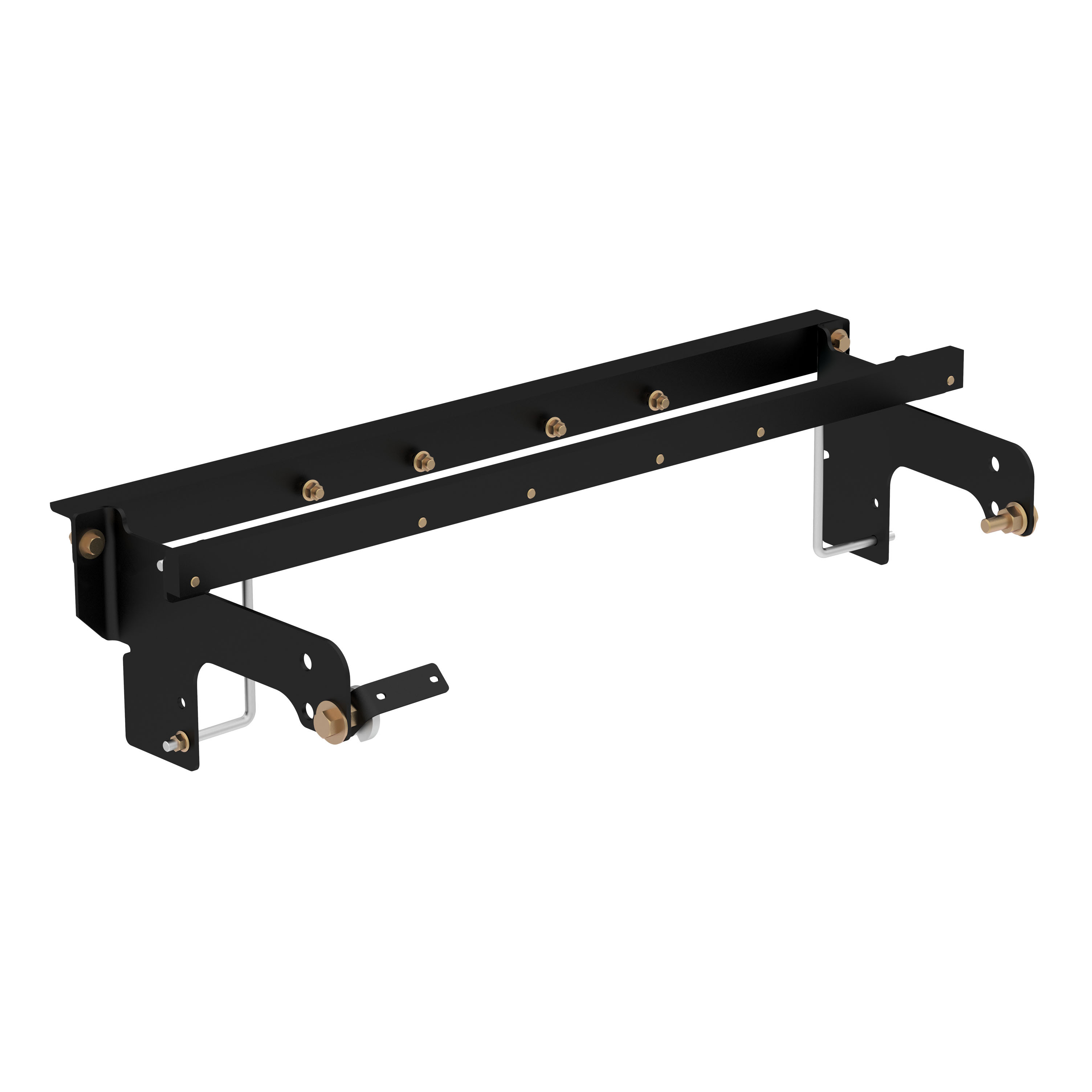
CURT 60648 Double Lock EZr Gooseneck Installation Brackets, Fits Select Chevrolet Silverado, GMC Sierra 2500, 3500 HDCURTOriginal price was $467.95. Current price is $289.99.In Stock
View productOur in-house experts typically reply within one business day.

CURT
Verify Fitment
Select your vehicle to confirm this part fits.


Always the correct part
We know our products
Quality Products
Free Shipping!
Always the correct part
We know our products
Quality Products
Free Shipping!
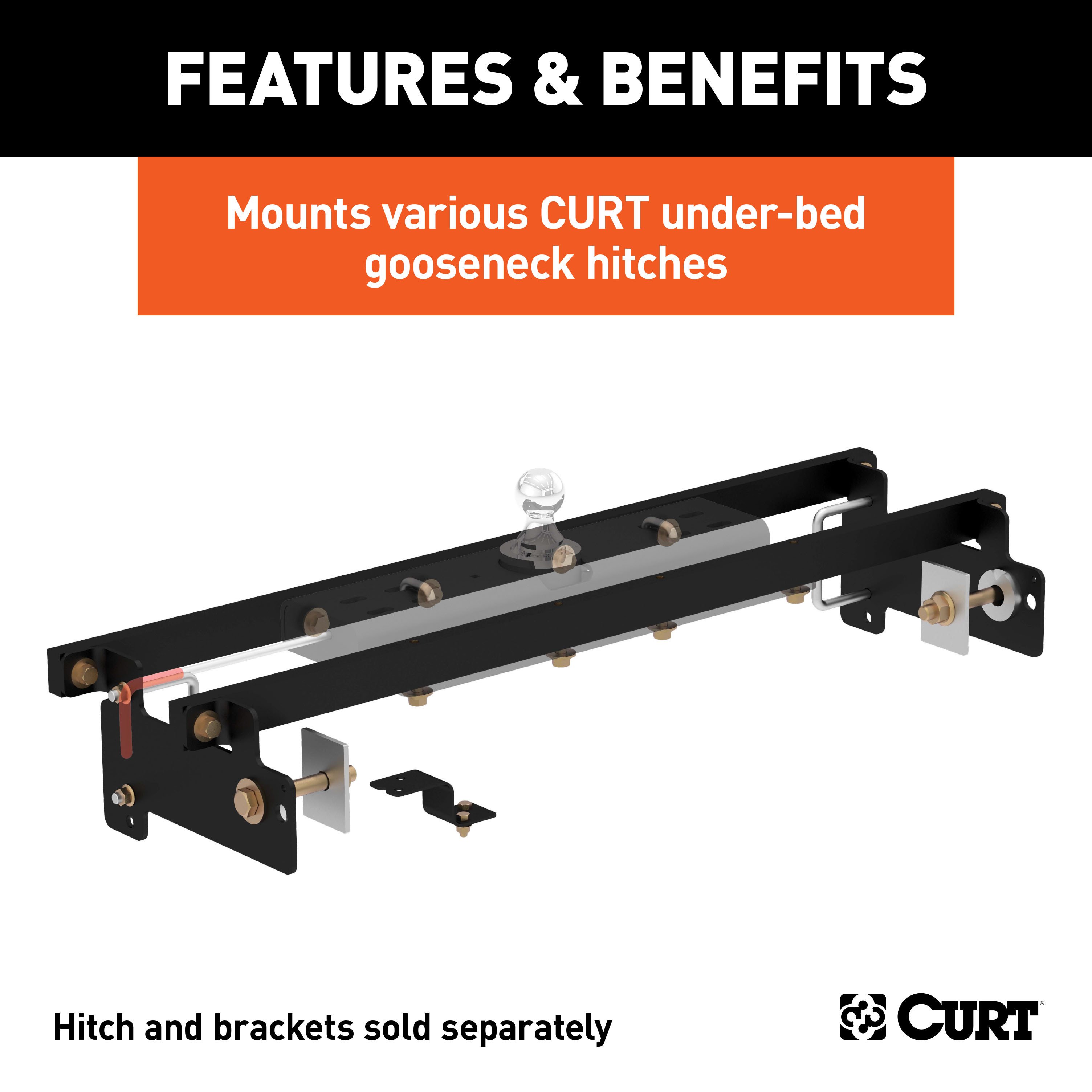
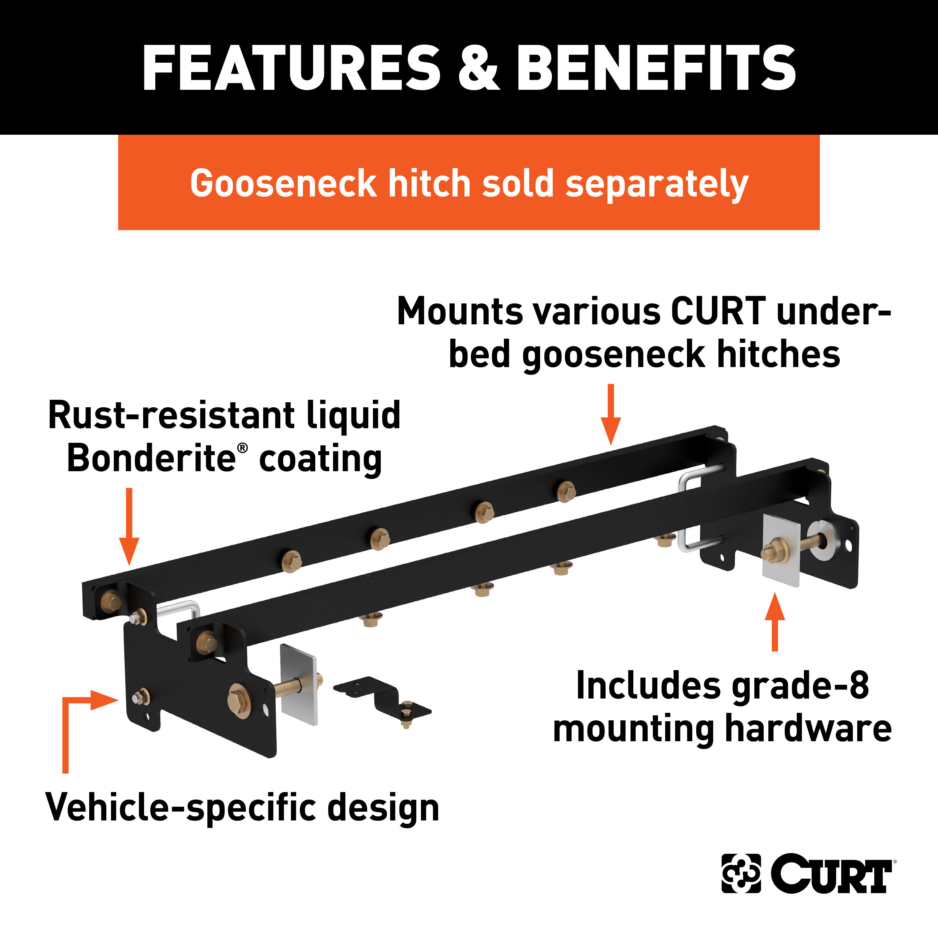
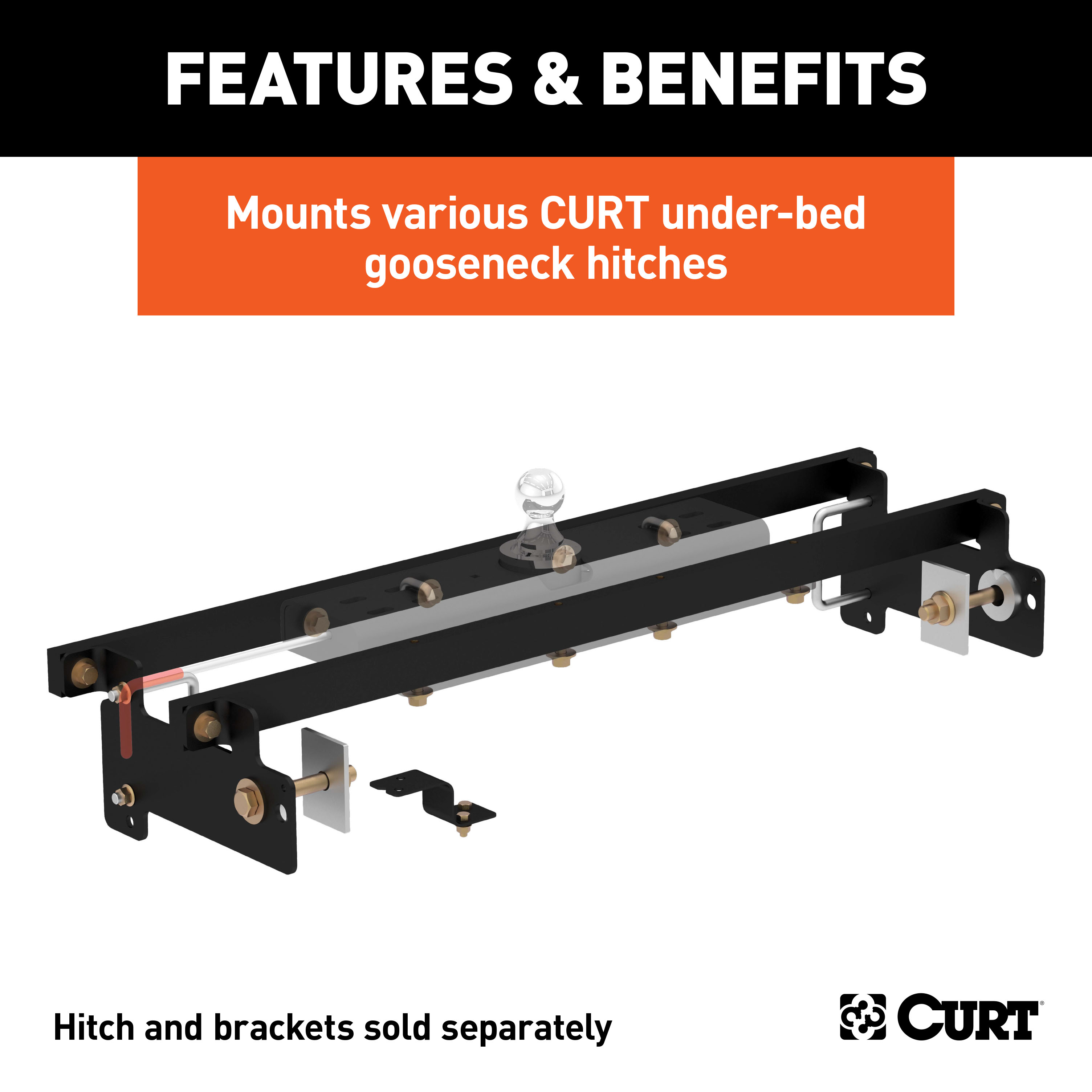
Includes mounting brackets only (gooseneck hitch sold separately)
Capacity limited to lowest-rated towing component

Includes mounting brackets only (gooseneck hitch sold separately)
Warranty: Limited Lifetime Warranty (One-Year Finish, One-Year Parts)
Finish: A-COAT
Installation Time Exact (Minutes): 0
Choosing the right gooseneck hitch is only half the battle in preparing your pickup truck for towing a gooseneck trailer. CURT gooseneck hitches are a premium option in the heavy-duty towing industry, but they are only one of the members in the heavyweight tag team that is CURT gooseneck towing. While a gooseneck hitch gets all the glory above the floor of your truck bed, gooseneck installation brackets provide sure footing and a solid foundation for that oversized gooseneck trailer. Gooseneck installation brackets work by bolting onto the frame of your truck, typically using pre-existing holes. With a set of brackets firmly bolted on, a gooseneck hitch is able to be attached and is given the strength it needs to manage the massive amount of weight of a gooseneck trailer. With so many gooseneck hitch options available from CURT, we wanted to make sure we offered the gooseneck installation products needed to give you a complete towing package. Our installation brackets fit multiple vehicles and hitch heads. This particular set of gooseneck installation brackets is able to work with certain CURT Double Lock gooseneck hitches. It is rated to the vehicle's maximum gross trailer weight capacity and provides a custom fit for certain years of the Chevrolet Silverado 1500 or 2500LD with new body style or GMC Sierra 1500 or 2500LD with new body style (see application info to verify fitment). With each gooseneck installation bracket sub kit, we provide the necessary hardware for an easier installation, and we coat our gooseneck brackets in a liquid A-coat to make sure rust and other potential damages are not a problem.

CURT offers a variety of high-quality trailer hitches and accessories for select vehicle models. Find the perfect fit for your towing needs at TowUniverse.
CURT, a Lippert brand, offers a complete line of towing products and is the leading manufacturer of custom-fit trailer hitches. We offer the broadest selection of custom-fit hitches, and each one is designed, welded, and coated in Wisconsin.
CURT is also a leader in flat towing products, as well as 5th wheel, gooseneck, and weight distribution hitches, ball mounts, electrical components, cargo solutions, and other towing accessories.
For everything from passenger cars and vans to full-size pickups and SUVs, CURT is 'The First Name in Towing Products®.'

Experts available to answer your questions
Call 888-634-94944 compatible vehicles
| Year | Make & Model | Notes |
|---|---|---|
| 2007 - 2018 | Chevrolet Silverado 1500 | No Drilling Required |
| 2019 | Chevrolet Silverado 1500 LD | No Drilling Required |
| 2007 - 2018 | GMC Sierra 1500 | No Drilling Required |
| 2019 | GMC Sierra 1500 Limited | No Drilling Required |
Yes, the Curt 60632 gooseneck hitch center section fits 2007 to current Chevrolet and GMC 1500 Silverado and Sierra trucks with the new body style, in all bed lengths (short, standard, and long box). It must be used with C-615 centers only. Confirm your truck has the new body style and that you will be using a C-615 center section with this product.
Yes, the Curt 60632 is designed for both Chevrolet Silverado and GMC Sierra 1500 trucks from 2007 to current, with the new body style, in all bed lengths. It must be used with C-615 centers only.
No. The Curt 60632 is designed for 2007 to current Chevrolet and GMC 1500 trucks only. It is not compatible with pre-2007 models.
No. The manual states this product is to be used with C-615 centers only. The C-615 center section is required for proper operation.
Yes, the Curt 60632 is designed for all bed lengths on 2007 to current Chevrolet and GMC 1500 trucks. However, installation procedures and mounting hole locations differ by bed length. Short bed models require specific mounting hole locations and a turning clearance check between the trailer front and truck cab before towing.
You must remove the spare tire and heat shields. Specifically, remove the heat shield from in front of the back crossmember and the heat shield from the back of the crossmember located near the front of the wheel well. The heat shield under the bed floor needs to be removed or a section cut out for the hitch assembly to fit. If your truck has wheel well liners, they may need to be temporarily removed for cross arm installation.
The manual does not specify whether battery disconnection is required. Consult the manufacturer or a qualified installer for guidance on this step.
Yes. You must drill a 4-inch hole in the truck bed floor. This hole is critical for correct installation. You can use a 4-inch hole saw or make a 4-inch circle and cut it out with a saber saw equipped with a metal cutting blade. If your truck has a plastic bed liner, you may drill through both, but it is more difficult to accurately locate the midpoint and keep the bed liner from moving while cutting.
Measure from the tailgate end of the truck bed by hooking a tape measure over the back of the truck box (not from the edge of the tailgate). Use the following distances: 69.30-inch bed: 42 7/16 inches; 78.70-inch bed: 42 7/16 inches; 97.60-inch bed: 49 1/2 inches. Next, mark the center between the wheel wells. This marks the center point for the drill hole. This location is critical and will put the ball 4 to 6 inches in front of the axle. Measure, mark, and saw carefully.
Yes. All models require modification or removal of heat shields. You must remove the heat shield from in front of the back crossmember and the heat shield from the back of the crossmember located near the front of the wheel well. The heat shield under the bed floor needs to be removed or a section cut out for the hitch assembly to be installed.
Possibly. The manual warns that brake, fuel, and electrical lines may need to be loosened or repositioned to provide clearance for new hardware. In step 3, you must remove all lines from the top of the frame rail on the driver side and lower the brake lines by unbolting the factory brake line bracket and replacing it with the Curt-supplied bracket.
The kit includes: 4 spacers (2.50 DIA. x .250" round hole, part CM-SP13); 2 U-bolts (1/2-13 x 4 1/8 x 4 3/4 x 1 1/2 SQ, part CM-1206-UBS); 2 U-bolts (1/2-13 x 4 1/8 x 6 x 1 1/2 SQ, part CM-1208-UBS); 4 serrated flange nuts (1/2-13 UNC, part 20-00062); 12 hex cap screws (1/2-13 UNC, 1-1/2 inch, part 10-10334); 12 flat washers (1/2 inch, part 30-00133); 12 lock washers (1/2 inch, part 30-00153); 2 flange nuts (M8x1.25, part 20-00168); 2 hex cap screws (M8x1.25, 20mm, part 10-10409); 2 hex bolts (part 10-10514); 2 flat washers (3/4 inch, part 30-00152); 2 serrated flange nuts (3/4-10 UNC, part 20-00106); 2 spacers (.250 x 3.00 x 4.00 inch, part CM-SP58); and 1 brake line bracket (11 GA., part CM-BLB).
The manual does not specify which tools are required. However, based on the installation steps, you will likely need: a tape measure, a 4-inch hole saw or saber saw with metal cutting blade, wrenches or sockets for 1/2-inch and 3/4-inch fasteners, a torque wrench (to torque fasteners to 110 ft-lbs and 227 ft-lbs), and possibly an overhead lifting device such as chain falls, engine hoist, or cable come-a-long. Consult the manufacturer or a qualified installer for a complete tool list.
No, but it is recommended. An overhead lifting device such as chain falls, engine hoist, or cable come-a-long can be used to lift the center section into place. You lower a loop of rope or chain through the hole in the truck bed floor and attach it to the round hitch receiver tube in the center section, then use the lifting device to raise the center section until the round hitch receiver tube fits in the hole in the truck bed floor. The lifting device should be disconnected before squaring the center section across the frame, installing the sideplates, and torquing fasteners.
The manual does not specify whether professional installation is required or recommended. Given the complexity of the installation, including drilling, multiple fastening points, and torque specifications, consult the manufacturer or a qualified installer to determine if professional installation is appropriate for your situation.
The installation order is: 1) Remove spare tire and heat shields; 2) Mark and drill the 4-inch hole in the truck bed; 3) Remove and reposition brake lines on the driver side; 4) Install the rear cross arm between the frame and truck bed; 5) Install the front cross arm between the frame and truck bed; 6) Install the center section by raising it above the fuel tank and threading bolts into the cross arms; 7) Install the sideplates with U-bolts and fasteners (finger tight); 8) Finish attaching sideplates with U-bolts (finger tight); 9) Torque all fasteners in the specified order.
Slide the rear cross arm between the frame and truck bed floor above the passenger side rear tire. After spanning the frames, rotate the cross arm vertically with the four center threaded holes towards the ground. On short bed applications, the cross arm should be located behind the bed rail support towards the rear of the truck. If your vehicle is equipped with wheel well liners, they may need to be temporarily removed for cross arm installation.
Slide the front cross arm between the truck frame and truck bed above the passenger side rear tire. With the cross arm spanning the truck frame, rotate it vertically with the holes towards the bottom. On short bed applications, the cross arm will be located in front of the bed rail support towards the rear of the truck. Once vertical, slide the cross arm up against the bed rail support.
Carefully raise the center section above the fuel tank from beneath the truck. Insert four 1/2-inch x 1 1/2-inch hex bolts with a washer and lock washer through each of the slots on the inside of the center section, and thread them finger tight into the front cross arm. Repeat that process for the rear cross arm. While installing, ensure that the round hitch cylinder that protrudes from the top of the center section fits into the hole in the bed of the truck.
Install the sideplates with the large hole towards the back of the truck, aligning them with the existing slot in the frame. Refer to Figure 1 on page 1 to determine which mounting plate hole to use for your bed length. Attach using a 3/4-10 x 5 1/4-inch hex bolt and 3/4-inch washer, pushing it through the frame while putting two CM-SP13 spacers on the bolt between the frame and sideplate, then attach the sideplate with a CM-SP58 spacer and a 3/4-inch flange nut (finger tight both sides). With the sideplates mounted at the slot, attach the flanges to the cross arms using two 1/2-inch x 1 1/2-inch hex bolts with 1/2-inch washers and 1/2-inch lock washers, threaded through the inside of the sideplate flanges into the cross arms (finger tight only). Then finish attaching sideplates to the frame using the provided U-bolts: use the larger U-bolt for long box applications and the smaller U-bolt for short box applications. Position the U-bolt from the inside of the truck frame, being careful not to damage or pinch the wiring harness or brake lines. Attach to the sideplate using two 1/2-inch flange nuts (finger tight only).
Use the larger U-bolt (1/2-13 x 4 1/8 x 6 x 1 1/2 SQ, part CM-1208-UBS) for long box applications. Use the smaller U-bolt (1/2-13 x 4 1/8 x 4 3/4 x 1 1/2 SQ, part CM-1206-UBS) for short box applications.
Torque all 1/2-inch fasteners to 110 ft-lbs and all 3/4-inch fasteners to 227 ft-lbs. When torquing U-bolts, tighten them slowly, alternating between the top and bottom of the U-bolt until equally tightened to a maximum of 40 ft-lbs. Torque in the following order: First, torque the center section to the front and rear cross arms. Second, torque the sideplates to the truck frame on both sides. Third, torque the sideplate flanges to the front and rear cross arms.
All 1/2-inch fasteners should be torqued to 110 ft-lbs.
All 3/4-inch fasteners should be torqued to 227 ft-lbs.
U-bolts should be tightened slowly, alternating between the top and bottom of the U-bolt until equally tightened to a maximum of 40 ft-lbs.
The manual does not provide wiring instructions for the Curt 60632 center section. It states to refer to gooseneck hitch instructions for installation and operation procedures. Consult the C-615 center section manual or the manufacturer for wiring guidance.
Before towing, you must: 1) Remove all rear window accessories; 2) On two-wheel drive trucks, perform a clearance check when the truck is both loaded and unloaded to verify the inverted ball will not interfere with the top of the differential; 3) On short bed models, check for adequate turning clearance between the front of all trailers and the truck cab; 4) Reference the clearance calculator to ensure the trailer will not interfere with the cab of the truck.
Yes. You must remove all rear window accessories before towing. This is stated as a warning on pages 1 and 2 of the manual.
On two-wheel drive trucks, a clearance check must be performed when the truck is loaded and unloaded to verify the inverted ball will not interfere with the top of the differential. This is critical because the hitch ball position may change relative to the differential depending on the truck's load.
On short bed models, you must check for adequate turning clearance between the front of all trailers and the truck cab before towing. This is necessary because the shorter bed length may result in reduced clearance when the trailer is turned.
Use the clearance calculation formula on page 3. Measure the distance from the cab to the ball center (X), the coupler overhang if applicable (W), and half the trailer width (Y). For a standard trailer: (X) - (Y) = (Z). For a trailer with overhang: [(X) - (W)] - (Y) = (Z). If (Z) is positive, the trailer will not interfere with the cab. If (Z) is negative, the trailer will interfere with the cab. Generally, 8-foot-wide trailers taper to 6 feet at the coupler, and 7-foot-wide trailers taper to 5 feet at the coupler. Reference the clearance calculator before towing.
The manual states do not exceed the recommended vehicle towing weight and do not exceed the vehicle manufacturer's recommended towing capacity, but does not specify the actual weight limit. Consult the vehicle manufacturer's specifications and the C-615 center section documentation for the maximum towing capacity.
After installation, check for proper torque on all nuts and bolts before each use. Also check for excessive wear. Check ball wear before each use. Do not tow a trailer with worn or damaged parts.
Maintenance is required every 30 days or prior to use. This includes: 1) Keep hitch ball lubricated regularly using silicone spray or equivalent to prevent wear and rust; 2) Keep hitch assembly free of dirt and other foreign debris; 3) Check for proper torque on all nuts and bolts before each use and check for excessive wear; 4) Check ball wear before each use.
Use silicone spray or equivalent to lubricate the hitch ball regularly. This prevents wear and rust.
Keep the hitch ball lubricated regularly. Maintenance is required every 30 days or prior to use.
The Curt 60632 fits 2007 to current Chevrolet and GMC 1500 Silverado and Sierra trucks with the new body style, all bed lengths. It must be used with C-615 centers only.
Yes, you must drill a 4-inch hole in the truck bed floor at a specific location based on your bed length (42 7/16 inches for 69.30 and 78.70-inch beds; 49 1/2 inches for 97.60-inch bed, measured from the tailgate end). You can use a 4-inch hole saw or saber saw with metal cutting blade.
Yes. All models require modification or removal of heat shields. You must remove the heat shield from in front of the back crossmember and from the back of the crossmember near the front of the wheel well.
The kit includes spacers, U-bolts, hex bolts, washers, lock washers, flange nuts, and a brake line bracket. See the Parts List on page 1 for complete details and part numbers.
Torque all 1/2-inch fasteners to 110 ft-lbs and 3/4-inch fasteners to 227 ft-lbs. U-bolts should be tightened to a maximum of 40 ft-lbs, alternating between top and bottom.
Remove all rear window accessories. On two-wheel drive trucks, verify the inverted ball will not interfere with the differential when loaded and unloaded. On short bed models, check turning clearance between trailer front and cab. Use the clearance calculator to ensure the trailer will not interfere with the cab.
Every 30 days or before use: lubricate the hitch ball with silicone spray, keep the assembly free of dirt, check torque on all fasteners, and check for ball wear. Do not tow with worn or damaged parts.
Remove spare tire and heat shields; drill the bed hole; reposition brake lines; install rear cross arm; install front cross arm; install center section; install sideplates; attach U-bolts; torque all fasteners in the specified order (center to cross arms, sideplates to frame, flanges to cross arms).
Use an overhead lifting device such as chain falls, engine hoist, or cable come-a-long to assist. Lower a loop of rope or chain through the hole in the truck bed floor and attach it to the round hitch receiver tube in the center section. Use the lifting device to raise the center section until the round hitch receiver tube fits in the hole in the truck bed floor. Maintaining upward pressure may facilitate fastening the crossmember to the center section, especially if the truck bed floor has been distorted downward from heavy use. Disconnect the lifting device before squaring the center section across the frame, installing the sideplates, and torquing fasteners.
If your vehicle is equipped with wheel well liners, they may need to be temporarily removed for cross arm installation. Remove the liners, install the cross arms, and then reinstall the liners.
When torquing U-bolts, tighten them slowly, alternating between the top and bottom of the U-bolt until equally tightened to a maximum of 40 ft-lbs. This ensures even pressure and prevents distortion.
If the clearance calculation shows a negative result (Z is negative), the trailer will interfere with the cab of the truck when turning. This is unsafe and you should not tow. Verify your measurements using the clearance calculation formula on page 3. If the result is still negative, the trailer is not compatible with your truck and hitch configuration.
On Sale Today
Original price was $444.95. Current price is $275.99.You save $168.96 (38%)
Free Shipping
Ships free on all orders
 Authorized Dealer


Quick Ship
In stock and ready to ship — order now!
Shipping from Eau Claire, WIFREE SHIPPING
Estimated delivery Tue, Oct 20 - Thu, Oct 22
Order before 2 PM EST Monday–Friday for same-day processing
Guaranteed safe & secure checkout
No reviews have been added for this product.