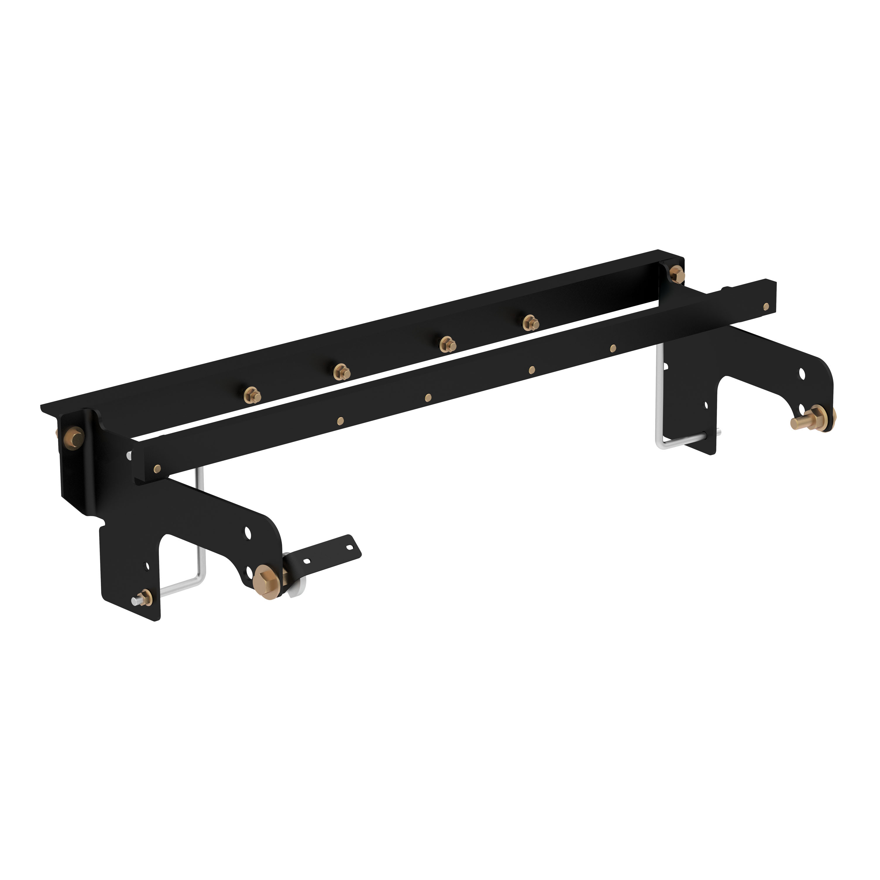
CURT 60648 Double Lock EZr Gooseneck Installation Brackets, Fits Select Chevrolet Silverado, GMC Sierra 2500, 3500 HDCURTOriginal price was $467.95. Current price is $289.99.In Stock
View productOur in-house experts typically reply within one business day.

CURT
Verify Fitment
Select your vehicle to confirm this part fits.
2020 - 2026 Chevrolet Silverado 3500 HD
Confirmed to Fit
2020 - 2026 Chevrolet Silverado 3500 HD
Confirmed to Fit
2020 - 2026 Chevrolet Silverado 3500 HD
Confirmed to Fit
2020 - 2026 GMC Sierra 3500 HD
Confirmed to Fit
2020 - 2026 GMC Sierra 3500 HD
Confirmed to Fit
2020 - 2026 GMC Sierra 3500 HD
Confirmed to Fit



Always the correct part
We know our products
Quality Products
Free Shipping!
Always the correct part
We know our products
Quality Products
Free Shipping!
On Sale Today
Original price was $561.95. Current price is $348.99.You save $212.96 (38%)
Free Shipping
Ships free on all orders
 Authorized Dealer


Quick Ship
In stock and ready to ship — order now!
Shipping from Eau Claire, WIFREE SHIPPING
Estimated delivery Tue, Oct 20 - Thu, Oct 22
Order before 2 PM EST Monday–Friday for same-day processing
Guaranteed safe & secure checkout
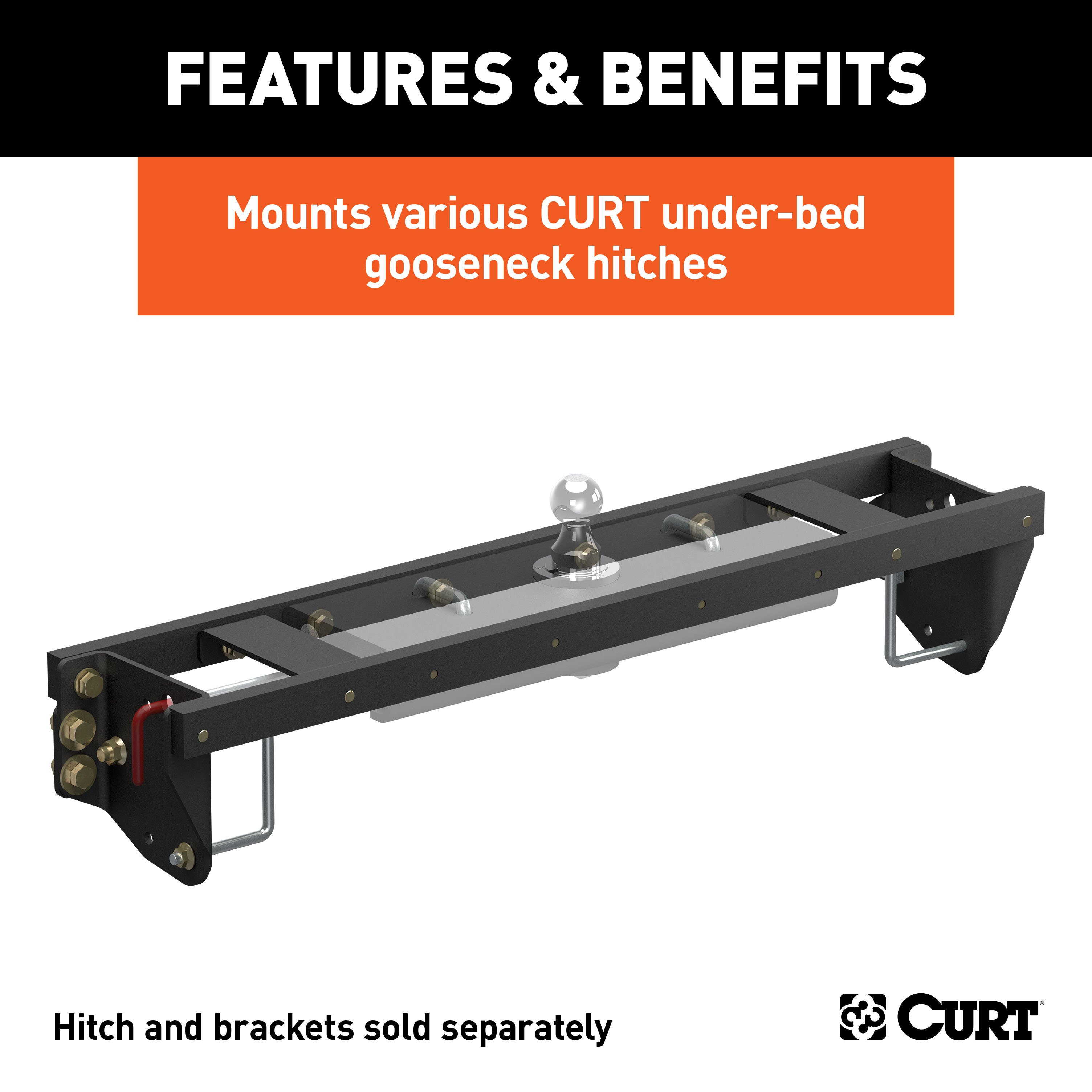
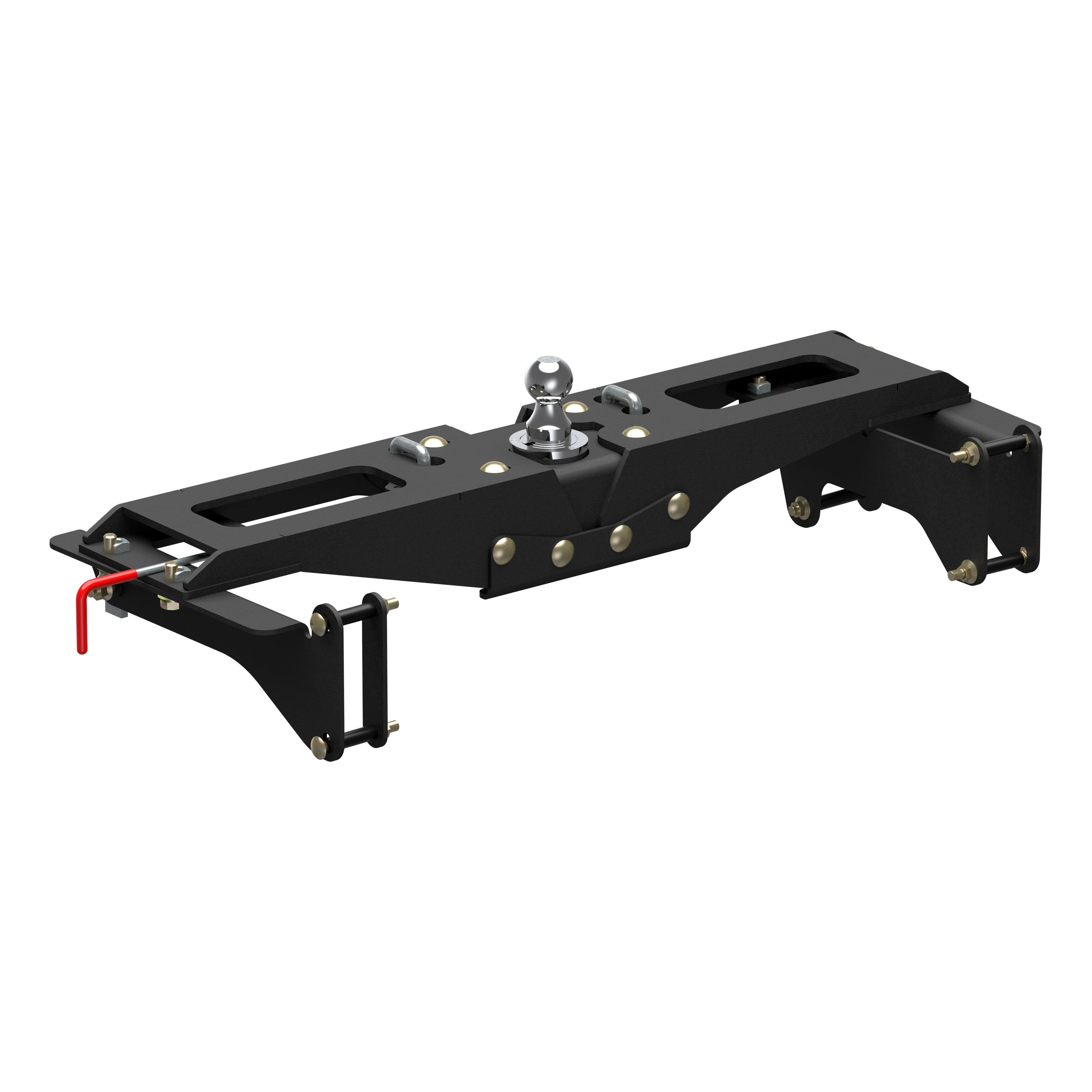
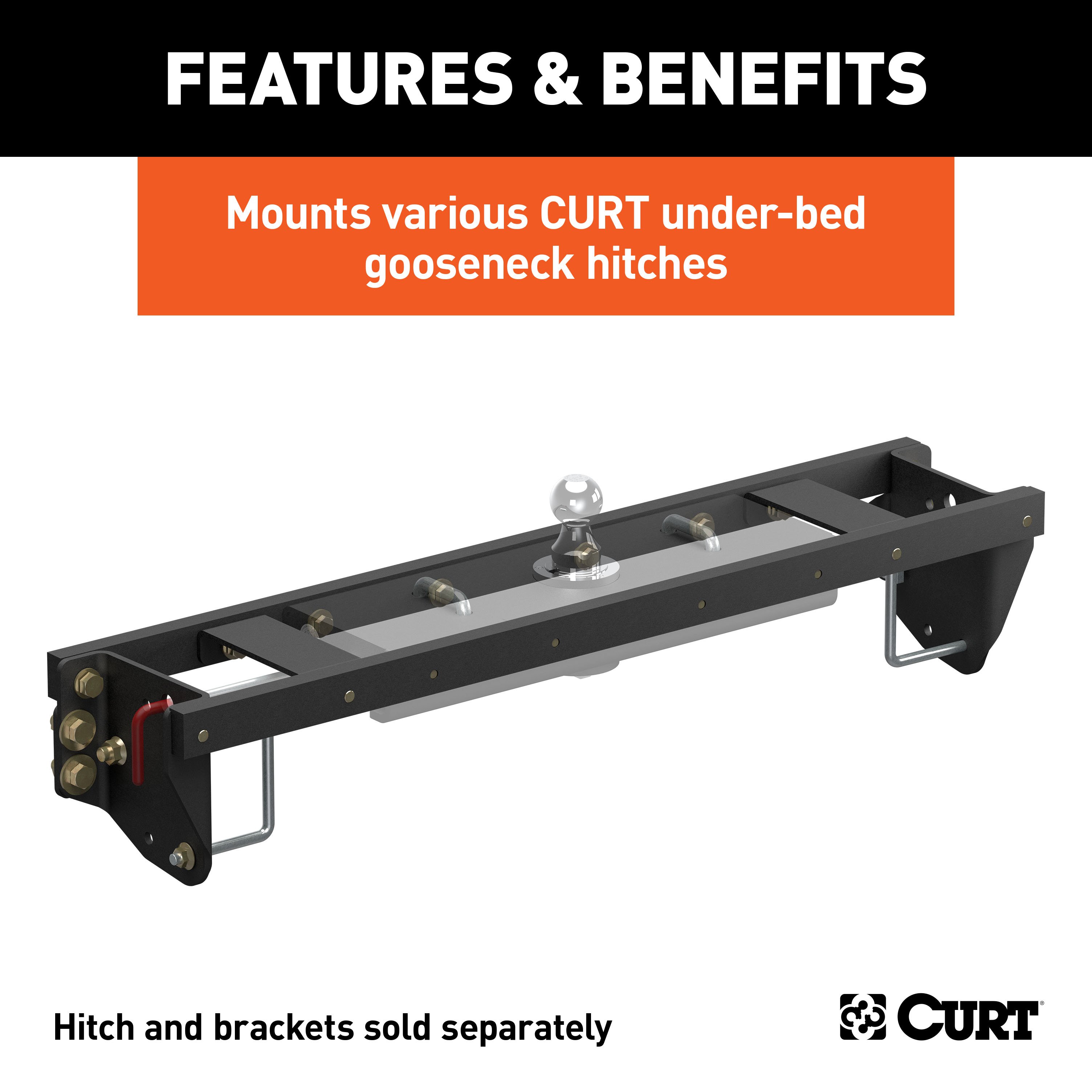
Includes mounting brackets only (gooseneck hitch sold separately)
Capacity limited to lowest-rated towing component

Includes mounting brackets only (gooseneck hitch sold separately)
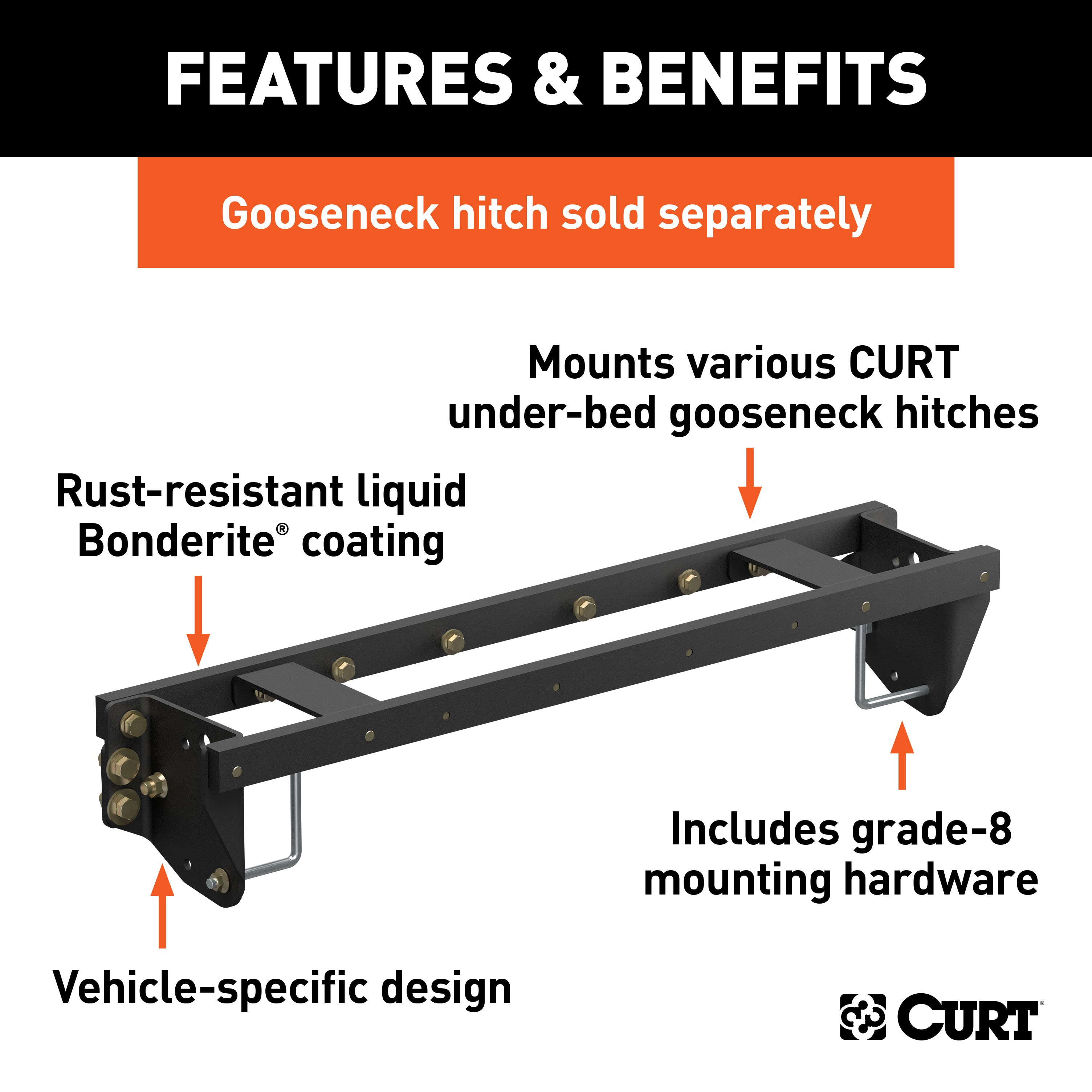
Warranty: Limited Lifetime Warranty (One-Year Finish, One-Year Parts)
Finish: A-COAT
Installation Time Exact (Minutes): 0
Choosing the right gooseneck hitch is only half the battle in preparing your pickup truck for towing a gooseneck trailer. CURT gooseneck hitches are a premium option in the heavy-duty towing industry, but they are only one of the members in the heavyweight tag team that is CURT gooseneck towing. While a gooseneck hitch gets all the glory above the floor of your truck bed, gooseneck installation brackets provide sure footing and a solid foundation for that oversized gooseneck trailer. Gooseneck installation brackets work by bolting onto the frame of your truck, typically using pre-existing holes. With a set of brackets firmly bolted on, a gooseneck hitch is able to be attached and is given the strength it needs to manage the massive amount of weight of a gooseneck trailer. With so many gooseneck hitch options available from CURT, we wanted to make sure we offered the gooseneck installation products needed to give you a complete towing package. Our installation brackets fit multiple vehicles and hitch heads. This particular set of gooseneck installation brackets is specifically designed to mount a CURT Double Lock EZr gooseneck hitch on certain years of the Chevy Silverado and GMC Sierra 2500 HD and 3500 HD (see application info to verify fitment). It features a laser-cut construction for a precise fit and is rated to the vehicle's maximum gross trailer weight capacity. With each gooseneck installation bracket sub kit, we provide the necessary hardware for an easier installation, and we coat our gooseneck brackets in a liquid A-coat to make sure rust and other potential damages are not a problem.

CURT offers a variety of high-quality trailer hitches and accessories for select vehicle models. Find the perfect fit for your towing needs at TowUniverse.
CURT, a Lippert brand, offers a complete line of towing products and is the leading manufacturer of custom-fit trailer hitches. We offer the broadest selection of custom-fit hitches, and each one is designed, welded, and coated in Wisconsin.
CURT is also a leader in flat towing products, as well as 5th wheel, gooseneck, and weight distribution hitches, ball mounts, electrical components, cargo solutions, and other towing accessories.
For everything from passenger cars and vans to full-size pickups and SUVs, CURT is 'The First Name in Towing Products®.'

Experts available to answer your questions
Call 888-634-9494Rediscover "Us" Time | Tested. Proven. Safe. Towing Products
8 compatible vehicles
| Year | Make & Model | Style | Notes |
|---|---|---|---|
| 2020 - 2026 | Chevrolet Silverado 2500 HD | — | Drilling Required - Installation Time - |
| 2020 - 2026 | Chevrolet Silverado 3500 HD | Crew Cab Pickup · 4-Door | Drilling Required - Installation Time - |
| 2020 - 2026 | Chevrolet Silverado 3500 HD | Extended Cab Pickup · 4-Door | Drilling Required - Installation Time - |
| 2020 - 2026 | Chevrolet Silverado 3500 HD | Standard Cab Pickup · 2-Door | Drilling Required - Installation Time - |
| 2020 - 2026 | GMC Sierra 2500 HD | — | Drilling Required - Installation Time - |
| 2020 - 2026 | GMC Sierra 3500 HD | Crew Cab Pickup · 4-Door | Drilling Required - Installation Time - |
| 2020 - 2026 | GMC Sierra 3500 HD | Extended Cab Pickup · 4-Door | Drilling Required - Installation Time - |
| 2020 - 2026 | GMC Sierra 3500 HD | Standard Cab Pickup · 2-Door | Drilling Required - Installation Time - |
The CURT 60701 Double Lock EZr Gooseneck Installation Brackets, Fits Select Chevrolet Silverado, GMC Sierra 2500, 3500 HD (Part #BKDK60701) fits the following vehicles: 2020-2026 Chevrolet Silverado 2500 HD; 2020-2026 Chevrolet Silverado 3500 HD; 2020-2026 GMC Sierra 2500 HD; 2020-2026 GMC Sierra 3500 HD. Always verify your specific year, make, and model before ordering.
The CURT 60701 Double Lock EZr Gooseneck Installation Brackets, Fits Select Chevrolet Silverado, GMC Sierra 2500, 3500 HD (Part #BKDK60701) fits 2020-2026 Chevrolet Silverado 2500 HD models. The 2026 model year is the last year covered by this part number. For newer models, check for an updated version.
Yes, the CURT 60701 Double Lock EZr Gooseneck Installation Brackets, Fits Select Chevrolet Silverado, GMC Sierra 2500, 3500 HD (Part #BKDK60701) is designed to fit the 2020-2026 Chevrolet Silverado 2500 HD.
The CURT 60701 Double Lock EZr Gooseneck Installation Brackets, Fits Select Chevrolet Silverado, GMC Sierra 2500, 3500 HD (Part #BKDK60701) Drilling is required for installation. Typical installation time is . Basic hand tools are typically all you need.
The 60701 SUBKIT is designed for Chevy & GMC 2500 / 3500 pickup trucks. It fits both long box (8') and standard bed models, and works with both two-wheel drive and four-wheel drive trucks. However, the kit is a subkit and must be used with the 60611 Center Section (sold separately) for complete installation. Confirm your truck model and bed length before purchasing.
The 60701 SUBKIT is a subkit only and is not complete on its own. It is designed for use with the 60611 Center Section, which is not included. You must purchase the 60611 Center Section separately to complete the gooseneck hitch installation. The manual states 'DESIGNED FOR USE WITH 60611 CENTER SECTION (NOT INCLUDED IN SUBKIT)'.
The 60701 SUBKIT can be installed on short bed models, but you must perform a turning clearance check to ensure the front of your trailer will not interfere with the truck cab during turns. The manual warns: 'ON SHORT BED MODELS, CHECK FOR ADEQUATE TURNING CLEARANCE BETWEEN THE FRONT OF ALL TRAILERS AND THE TRUCK CAB.' Use the clearance calculation formula provided on page 4 of the manual to verify compatibility with your specific trailer.
Yes. On two-wheel drive trucks, you must perform a clearance check both when the truck is loaded and when it is unloaded to verify that the inverted ball will not interfere with the top of the differential. The manual states: 'ON TWO WHEEL DRIVE TRUCKS A CLEARANCE CHECK MUST BE PERFORMED WHEN TRUCK IS LOADED AND UNLOADED TO VERIFY THE INVERTED BALL WILL NOT INTERFERE WITH THE TOP OF THE DIFFERENTIAL.' This is a critical safety check before using the hitch.
Yes, the 60701 SUBKIT is designed for long box (8') models. However, long box models require special mounting plate installation. The mounting plates [F] and hardware must be installed to shift the kit rearward on the vehicle 2 1/2 inches for bed support clearance. See page 1 'MOUNTING LOCATIONS' for the specific mounting hole positions for long box models.
Required tools are: safety glasses, T25 socket, rotary tool with cut wheel, ratchet, 3" and 6" socket extensions, 13mm, 18mm, and 24mm sockets, 3/4" and 15/16" sockets, 3/4" end wrench, adjustable wrench, and torque wrench. A crescent wrench is also helpful as a lever to ease cross arm rotation during installation.
The kit includes: 2 square hole spacers (CM-SP9), 2 U-bolts 1/2-13 (CM-1215-UBS), 8 hex cap screws 5/8-11 x 1-1/2 (10-10038), 2 carriage bolts 5/8-11 x 1-3/4 (10-10292), 8 hex cap screws 1/2-13 x 1-1/2 (10-10334), 4 serrated flange nuts 1/2-13 (20-00062), 6 serrated flange nuts 5/8-11 (20-00105), 8 split-ring washers 1/2 (30-00149), 8 flat washers 5/8 (30-00131), 4 flat washers 5/8 (30-00204), 4 hex cap screws 5/8-11 x 1-3/4 (10-10296), and 2 pieces of 5/8" fishwire. Structural components include driver side plate, passenger side plate, rear cross arm, front cross arm, 2 brackets, and 2 mounting plates.
Yes. The manual lists 'LOWER SPARE TIRE' as a required pre-installation step. This must be done before beginning the installation process.
Yes. All models require modification or removal of heat shields. The manual states 'ALL MODELS REQUIRE MODIFICATION OR REMOVAL OF HEAT SHIELDS.' In step 2, you remove 4 fasteners holding the rear heat shield using a 13mm socket. The manual also notes to 'TRIM HEAT SHIELD BETWEEN BED SUPPORTS' as shown in Figure A. Specific modification details for other heat shields are not provided in the manual.
The manual does not specify whether the battery must be disconnected. However, the manual warns that 'BRAKE, FUEL, AND ELECTRICAL LINES MAY NEED TO BE LOOSENED OR REPOSITIONED TO PROVIDE CLEARANCE FOR NEW HARDWARE.' Consult the vehicle manufacturer's service manual or a qualified technician before beginning work if you will be working near electrical components.
Possibly. The manual warns: 'BRAKE, FUEL, AND ELECTRICAL LINES MAY NEED TO BE LOOSENED OR REPOSITIONED TO PROVIDE CLEARANCE FOR NEW HARDWARE.' Whether repositioning is required depends on your specific truck configuration. Inspect the frame rails and mounting areas carefully during installation. If lines interfere with the cross arms or mounting hardware, they must be carefully loosened and repositioned to provide clearance. Do not cut or damage any lines.
Yes, if your truck has a wheel well cover. Step 1 states: 'If present temporarily remove wheel well cover, by removing (6) fasteners using T-25 socket, on both sides of vehicle. Set aside wheel well and hardware for trim and reinstallation.' After installation, you will trim the wheel well liner using Figure A as a trim diagram and reinstall it.
Yes. Step 2 requires you to 'Remove (4) fasteners holding rear heat shield using a 13mm socket and return to owner. Lower exhaust by locating (4) exhaust hangers along exhaust system. Support exhaust to avoid damaging.' The exhaust must be lowered to provide clearance for the cross arms. Support it securely to prevent damage.
Step 3 describes the process: First, run a 1/2"-13 bolt or tap through the front cross arm [D] and rear cross arm [C] threads to remove powder coating and debris. Slide both cross arms between the frame and bottom of the truck bed, positioned approximately above the rear tire. Once the cross arms span across the vehicle resting on both frame rails in the correct position (see Figure A), rotate them vertically. Important: the outside tapped holes in the front and rear cross arms are offset by 1/8" and must be rotated so holes are offset towards the frame (see Figure B). A crescent wrench can be used as a lever to ease rotation. Temporarily loosening 6 fasteners holding the bed to frame using an 18mm socket may ease the rotation process.
The fishwire technique is used in step 5 to secure carriage bolts and spacers through the frame access hole without losing hardware inside the frame. The manual states: 'Fishwire (2) 5/8" carriage bolts [4] with CM-SP9 spacers [1] in position through access hole. Leave fishwires [12] attached to hardware to prevent loss of hardware in vehicle frame.' The fishwire keeps the bolts and spacers tethered so they cannot fall into the frame cavity. After the side plate is attached to the frame, carefully remove the fishwire.
Step 5 specifies: 'Secure 1/2" U-bolts [2] on inside of frame rail, avoiding brake lines, on both sides of vehicle.' The U-bolts (CM-1215-UBS) must be installed on the inside of each frame rail. Take care to avoid brake lines when positioning them. The U-bolts are then secured with the appropriate nuts and washers as listed in the parts list.
Step 6 describes bracket installation: 'Raise bracket [E] into mounting location, on both sides of vehicle. Use 5/8" hex bolt [3] with 5/8" washer [9] to secure bracket to cross arms.' Install one bracket on each side of the vehicle. Each bracket is secured to the cross arms using a 5/8" hex bolt and 5/8" washer.
Step 7 explains: 'Attach side plates to cross arms. Insert 5/8" hex bolt [3] with 5/8" washer [9] through front flange of side plate and into threaded cross arms holes on both sides of vehicle.' The driver side plate [A] and passenger side plate [B] are each secured to the cross arms using 5/8" hex bolts and washers. Be sure the center section is centered on the vehicle by verifying that the sides of the center section are in the same location on the bed ribs.
Step 8 specifies a three-step torque sequence: FIRST, torque side plates and mounting plates (long box models only) to truck frame on both sides. SECOND, torque center section, brackets, and mounting plates (long box models only) to front and rear cross arms. THIRD, torque side plates to front and rear cross arms. Torque all 5/8" fasteners to 180 ft-lbs and all 1/2" fasteners to 110 ft-lbs. Follow this sequence exactly to ensure proper load distribution.
All 5/8" fasteners on the 60701 SUBKIT must be torqued to 180 ft-lbs. This applies to hex bolts, carriage bolts, and all other 5/8" fasteners used in the installation.
All 1/2" fasteners on the 60701 SUBKIT must be torqued to 110 ft-lbs. This applies to U-bolts, hex cap screws, and all other 1/2" fasteners used in the installation.
The square hole spacer (CM-SP9) measures 0.375 x 1.25 x 2.50 inches. Two spacers are included in the kit.
The kit includes two 1/2-13 x 5 1/4 x 6 x 1 1/2 square U-bolts (part number CM-1215-UBS). These are torqued to 110 ft-lbs as 1/2" fasteners.
The rear cross arm [C] (part number 60701-RCA) measures 47.00 inches.
The front cross arm [D] (part number 60701-FCA) measures 47.25 inches.
Yes. Step 4 requires you to 'Loosely attach center section to cross arms' before the torque sequence in step 8. The center section cylinder should offset towards the rear of the vehicle. Verify the center locator is inserted into the center section cylinder prior to installing. Applying force to the center section towards the truck bed will help install hardware in the correct position. The center section is then torqued in the second step of the torque sequence.
Step 7 states: 'Be sure center section is centered on vehicle by verifying sides of center section are in same location on bed ribs.' Check that both sides of the center section align equally with the truck bed ribs before final torquing.
The manual emphasizes: 'DO NOT EXCEED RECOMMENDED VEHICLE TOWING WEIGHT!' This warning appears on every page. Exceeding the recommended towing weight can cause structural failure and loss of control. The specific recommended towing weight is not provided in this manual; consult the vehicle manufacturer's specifications and the 60611 Center Section documentation for the exact weight limit.
Before using any trailer, you must perform a turning clearance check to ensure the front of the trailer will not interfere with the truck cab during turns. Use the clearance calculation formula on page 4: (CAB TO BALL CENTER) - 1/2 (TRAILER WIDTH) = (MINIMUM CLEARANCE). If the result is positive, the trailer will not interfere. If negative, the trailer will interfere with the cab. The manual provides an example calculation and a blank form for your specific measurements.
On two-wheel drive trucks, you must verify clearance both when the truck is loaded and when it is unloaded. The specific check is to ensure the inverted ball will not interfere with the top of the differential in either condition. This is critical because the differential height changes with vehicle load. Perform this check before using the hitch.
The manual notes: 'REMOVAL OF REAR WINDOW ACCESSORIES MAY BE REQUIRED.' Whether removal is necessary depends on your specific truck configuration and the height of the rear window accessories. Inspect the installation area to determine if accessories will interfere with the cross arms or center section.
After installation, perform these checks: (1) Verify all fasteners are tight by checking them with a torque wrench. (2) Inspect all structural components to ensure they are sound and undamaged. (3) On short bed trucks, perform the turning clearance check with your trailer. (4) On two-wheel drive trucks, verify the inverted ball does not interfere with the differential when the truck is both loaded and unloaded. (5) Reinstall the wheel well cover and trim it as needed using Figure A. (6) Ensure the center section is centered on the vehicle by checking alignment with bed ribs.
The manual states: 'PERIODICALLY CHECK THIS GOOSENECK HITCH TO ENSURE THAT ALL FASTENERS ARE TIGHT AND THAT ALL STRUCTURAL COMPONENTS ARE SOUND.' The specific interval is not provided, but periodic inspection is essential for safe operation. Check fasteners and structural integrity regularly, especially before towing and after heavy use.
No. The manual explicitly states 'NO DRILLING INTO FRAME' and 'NO MEASURING DRILL LOCATIONS.' The 60701 SUBKIT uses existing frame holes and does not require drilling into the truck frame. However, you will need a rotary tool with a cut wheel to trim the heat shield and wheel well cover as needed.
No. The manual explicitly states: '*** DO NOT DRILL DIMPLES IN TRUCK BED FOR THE GOOSENECK BALL ***' Drilling dimples is not required and should not be done. The gooseneck ball is mounted as part of the 60611 Center Section installation, which is covered in separate instructions.
The manual requires you to 'Lower exhaust by locating (4) exhaust hangers along exhaust system. Support exhaust to avoid damaging' in step 2. The manual does not specify whether the exhaust should be permanently lowered or can be raised back after installation. Consult a qualified technician or the vehicle manufacturer to determine the proper final exhaust position that maintains adequate clearance while allowing normal operation.
The outer tapped holes in the front and rear cross arms are offset by 1/8 inch. These holes must be rotated so they are offset towards the vehicle frame, not away from it. This offset is critical for proper alignment and must be verified during installation step 3.
On long box (8') models, the mounting plates [F] and hardware must be installed to shift the kit rearward on the vehicle 2 1/2 inches for bed support clearance. This shift is required to prevent interference with the truck bed supports. See page 1 'MOUNTING LOCATIONS' for the specific mounting hole positions for long box models.
Yes, the 60701 SUBKIT fits Chevy & GMC 2500/3500 trucks in both long box (8') and standard bed configurations, two-wheel and four-wheel drive. It is a subkit and requires the separate 60611 Center Section to complete the installation.
Yes. All models require modification or removal of heat shields. You must remove the rear heat shield and lower the exhaust system by supporting it at the four exhaust hangers. Heat shields between bed supports must be trimmed.
No. The manual explicitly states 'NO DRILLING INTO FRAME' and 'NO MEASURING DRILL LOCATIONS.' The kit uses existing frame holes. Do not drill dimples in the truck bed for the gooseneck ball.
Torque all 5/8" fasteners to 180 ft-lbs and all 1/2" fasteners to 110 ft-lbs. Follow the three-step torque sequence: first side plates and mounting plates to frame, second center section and brackets to cross arms, third side plates to cross arms.
On short bed models, you must check turning clearance between the trailer front and truck cab using the formula: (CAB TO BALL CENTER) - 1/2 (TRAILER WIDTH) = (MINIMUM CLEARANCE). If the result is negative, the trailer will interfere with the cab.
On two-wheel drive trucks, verify the inverted ball will not interfere with the differential top when the truck is both loaded and unloaded. This check must be performed before using the hitch.
Periodically check that all fasteners are tight and all structural components are sound. Retorque fasteners as needed. Do not exceed the recommended vehicle towing weight.
Step 3 provides a solution: 'A crescent wrench can be used as a lever on cross arm to ease rotating process.' Additionally, 'Temporarily loosening (6) fasteners holding bed to frame, using 18mm socket may ease rotation of cross arm.' Use the crescent wrench as a lever for additional mechanical advantage, and consider temporarily loosening the bed fasteners to allow the bed to shift slightly and provide more clearance for rotation.
Step 3 specifies: 'Outside tapped holes in front and rear cross arms are offset by 1/8" and cross arms need to be rotated so holes are offset towards frame, see FIGURE B.' If holes do not align, verify the cross arms are rotated so the offset is towards the frame, not away from it. Figure B shows the correct orientation. Rotate the cross arms until the offset holes point toward the frame rails.
Step 7 states: 'Be sure center section is centered on vehicle by verifying sides of center section are in same location on bed ribs.' Check that both sides of the center section align equally with the truck bed ribs. If not centered, loosen the fasteners connecting the side plates to the cross arms and shift the center section until it is properly centered, then retorque in the correct sequence.
Step 1 specifies: 'If present temporarily remove wheel well cover, by removing (6) fasteners using T-25 socket, on both sides of vehicle.' There are 6 fasteners per side (12 total) holding the wheel well covers. Use a T25 socket to remove them. Set aside the wheel well covers and hardware for later trimming and reinstallation.
Step 2 states: 'Lower exhaust by locating (4) exhaust hangers along exhaust system.' The exhaust hangers are located along the exhaust system between the engine and the rear of the vehicle. There are 4 hangers total. Support the exhaust carefully at these points to avoid damaging it while lowering.
Step 2 specifies: 'Remove (4) fasteners holding rear heat shield using a 13mm socket.' Use a 13mm socket to remove the 4 fasteners. If they are stuck, apply penetrating oil and allow it to soak before attempting removal again.
If your clearance calculation results in a negative number, the trailer will interfere with the cab during turns. This is unsafe and the hitch cannot be used with that trailer. You must either use a different trailer with a shorter coupler overhang or a narrower width, or use a truck with a longer wheelbase. Do not attempt to use the hitch if interference is detected.
If the inverted ball interferes with the differential when the truck is loaded, the hitch cannot be used safely in that condition. Do not tow with the truck loaded. Consult the vehicle manufacturer or a qualified technician to determine if modifications are possible, or consider using a different hitch design that provides adequate clearance.
No reviews have been added for this product.