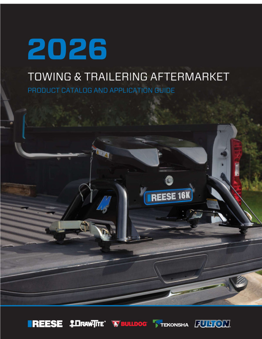

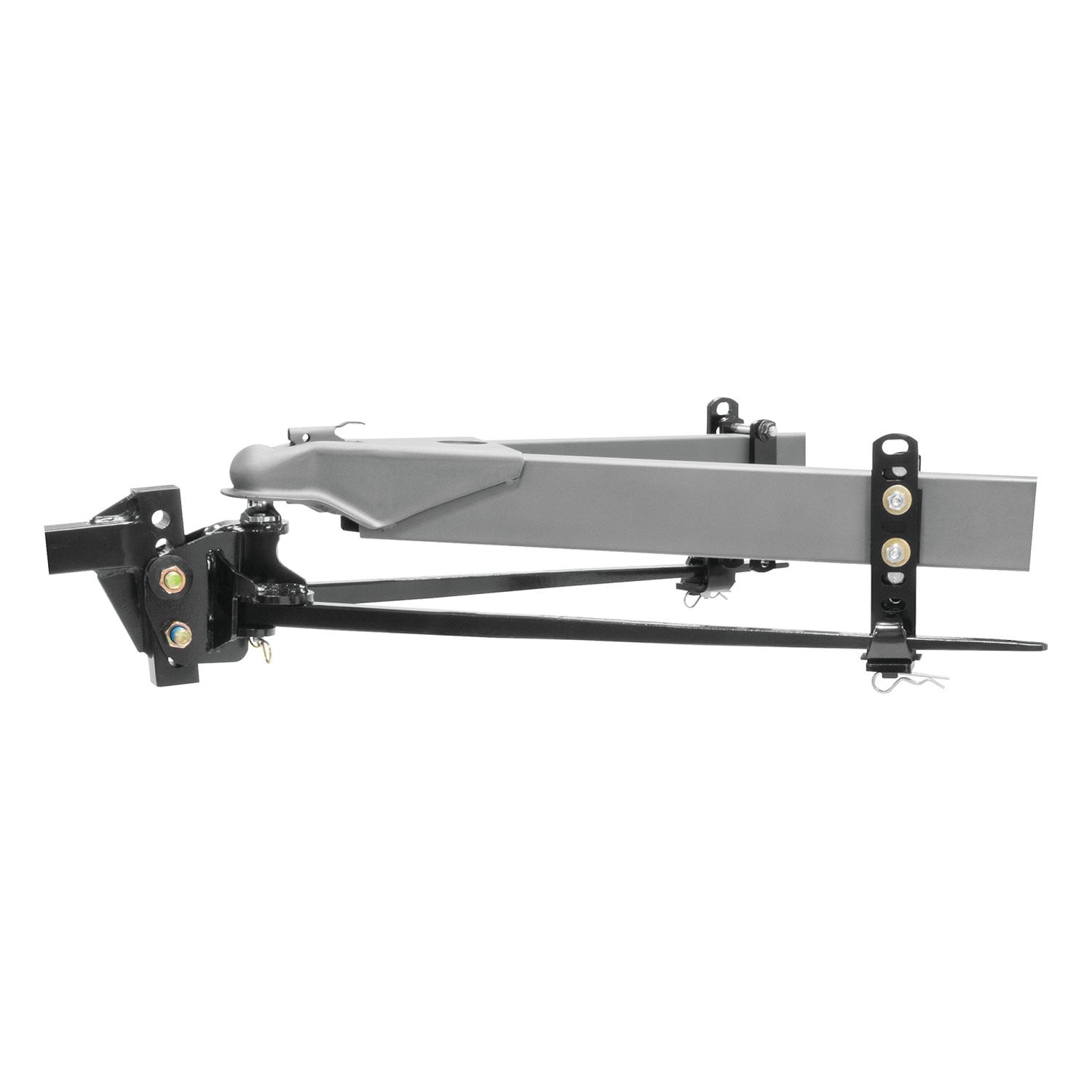
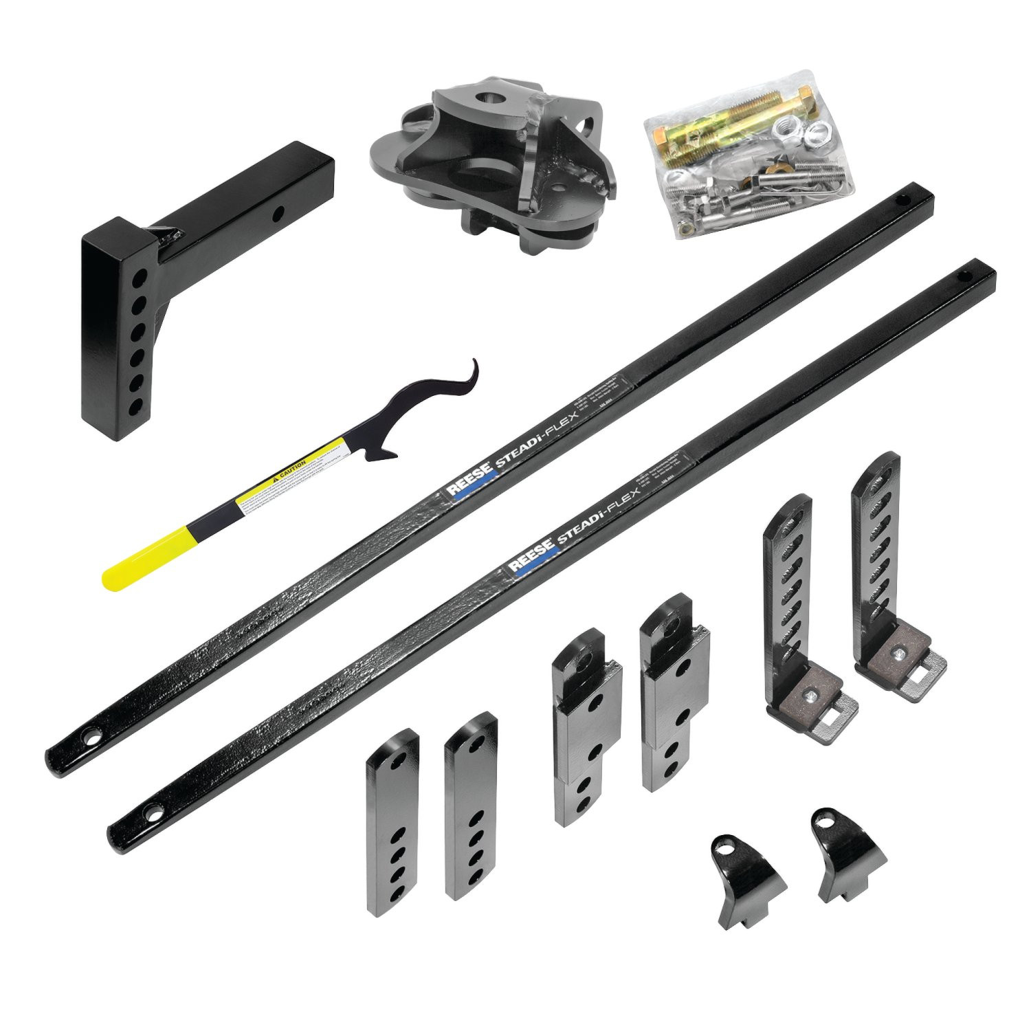
Reese Steadi-Flex Integrated Sway Control Weight Distribution Kit, 12,000 lbs. Capacity, Shank IncludedReese$1,086.96In Stock
View productOur in-house experts typically reply within one business day.

Reese


Always the correct part
We know our products
Quality Products
Free Shipping!
Always the correct part
We know our products
Quality Products
Free Shipping!

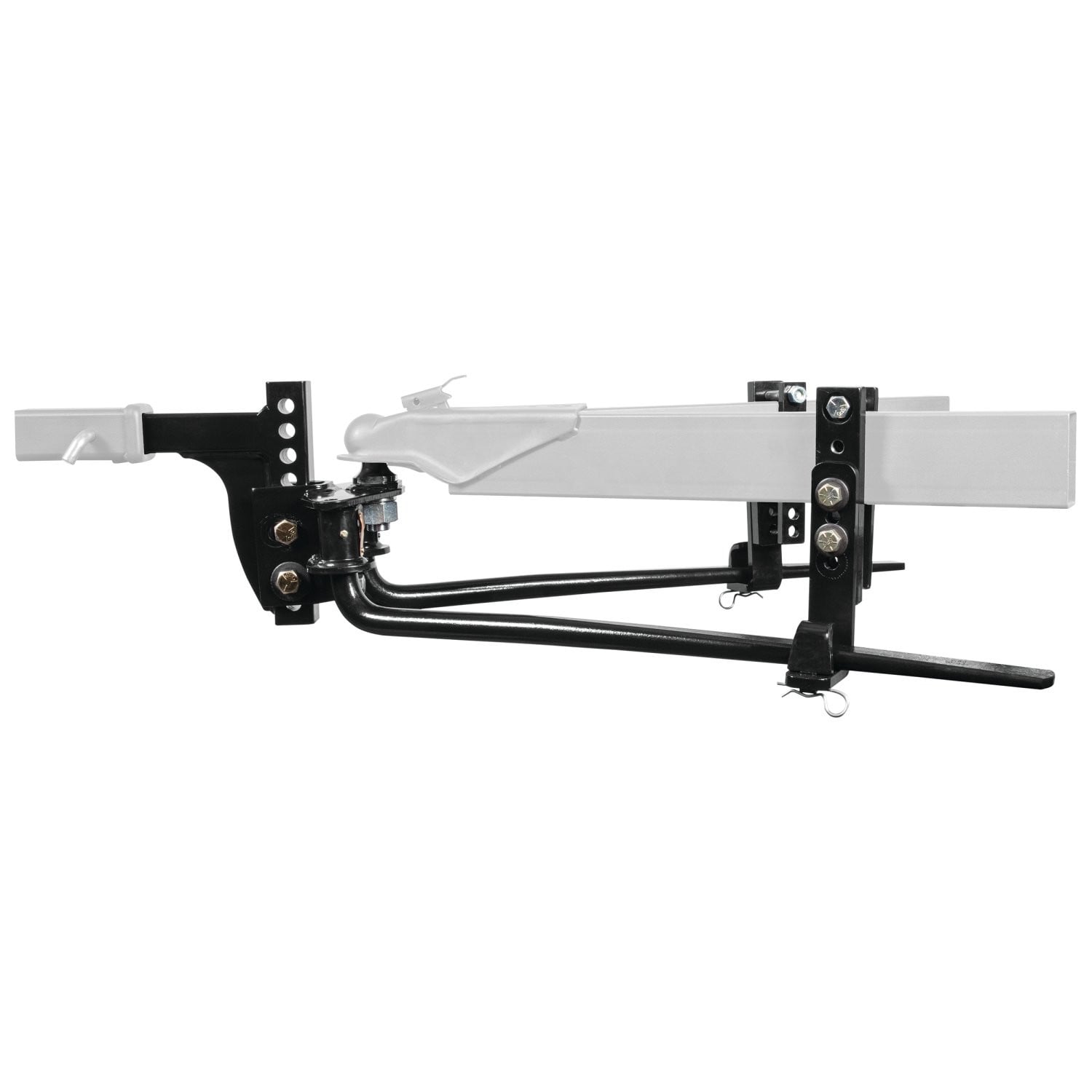
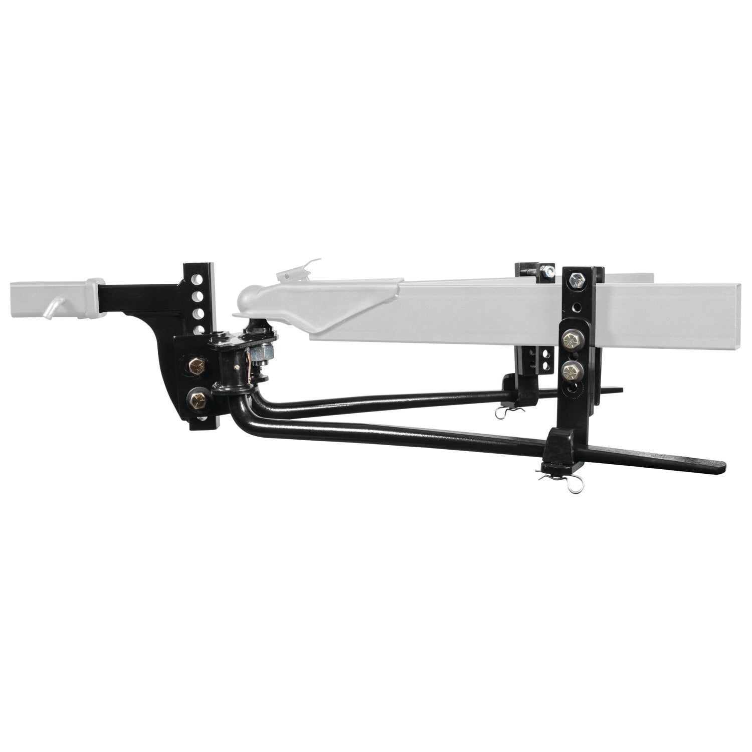
This weight distributing system is designed with tapered spring bars for a softer ride. Friction material, used for say control, provides a quiet ride. Wide spring bars, with a simple pin and clip assembly, reduce wear in the head and on the friction pads.
| BRAND: | REESE |
| PART NUMBER: | 66558 |
| WARRANTY: | LIMITED LIFETIME WARRANTY |
| WEIGHT: | 73 LBS |
| CAPACITY: | 6,000 LBS. |
| GROSS TONGUE WEIGHT: | 600 LBS. |
| INCLUDES SWAY CONTROL: | YES |
| UNIVERSAL OR SPECIFIC FIT: | UNIVERSAL |
| LENGTH: | 35 IN. |
| SAFETY CHAINS INCLUDED: | NO |
| MATERIAL: | STEEL |
| MOUNTING HARDWARE INCLUDED: | YES |
| ADJUSTABLE ARMS: | YES |
| MOUNTING BRACKET POSITION: | 25 IN. TO 32 IN. |
| COLOR: | BLACK |
| BOLT GRADE: | Grade 5 & Grade 8 |
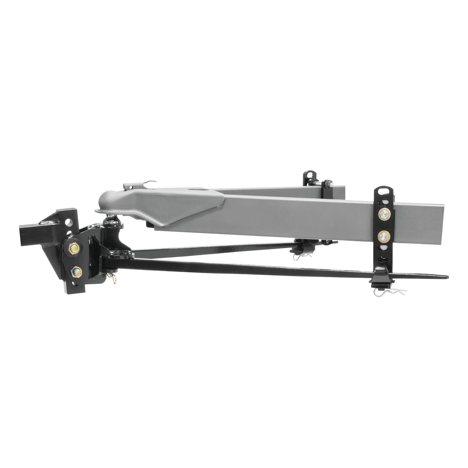

Reese has designed towing equipment since 1952 and remains a benchmark for heavy-duty towing. The line covers fifth wheel hitches such as the modular M5, gooseneck couplers including the Goose Box, air-ride and short-bed pin boxes, weight distribution systems with active sway control, and the accessories that connect them, all built to exceed published industry standards.
Reese has been pioneering towing performance since 1952, when Margaret Reese asked her husband TJ to stop travel trailers rocking every time somebody walked through them. His answer, the first pair of stabilising jacks, was simple and effective enough to change the RV industry. From that starting point Reese grew into a designer and manufacturer of complete towing systems, and today it anchors the heavy-duty end of the Horizon Global towing portfolio.
Fifth wheel towing is where the brand's engineering is most visible. The M5 fifth wheel hitch uses a modular design that breaks into manageable sections for assembly, with a wider stance, tighter tolerances and a shock absorption system aimed at the jolts that travel up through a truck bed. For owners who would rather tow from a gooseneck coupler and keep the bed clear, the Goose Box 20K replaces the trailer's king pin with a gooseneck connection carrying its own air-ride cushioning.
Pin boxes are a Reese speciality. The 5th Airborne uses air-ride technology to dampen road shock and reduce the chucking motion that makes fifth wheel towing tiring, while the Sidewinder was designed for short-bed pickups, pivoting the connection point so the trailer can turn sharply without the front cap meeting the cab.
For conventional towing, Reese weight distribution systems restore load to the tow vehicle's front axle and control sway. The Pro Round Bar distributes weight evenly while damping sway, and the Pro Dual Cam II uses active cam-based sway control that works harder the stronger the sway force becomes. Complete kits pair bars, head and shank to a rated tongue weight, and dedicated sway control kits can be added to existing setups. The products suit RV owners, horse and livestock haulers and anyone towing near the upper end of a vehicle's rating.
Experts available to answer your questions
Call 888-634-9494Lifetime
The REESE Steadi-Flex is a weight distribution system that uses spring bars and friction pads to transfer tongue weight from the tow vehicle's rear axle to its front axle and the trailer axle. This improves stability, braking, and handling when towing. Two models are available: 66557 (250–400 lb tongue weight) and 66558 (400–600 lb tongue weight).
The 66557 is rated for trailers with tongue weights of 250–400 lb. Weigh your loaded trailer tongue first. If the actual tongue weight is at or below 400 lb, the 66557 will fit. The system also requires a tubular A-frame trailer with a frame height of 4" to 5" (use Fig. 3) or 3" to 3.5" (use Fig. 4). Frame brackets cannot be installed on 2" wide frames.
The 66558 is rated for trailers with tongue weights of 400–600 lb. Weigh your loaded trailer tongue first. If the actual tongue weight is between 400 and 600 lb, the 66558 will fit. The system requires a tubular A-frame trailer with a frame height of 5" or greater. Frame brackets cannot be installed on 2" wide frames.
Yes, but the frame brackets may need to be installed upside down. If you have a 6" tall frame with a bottom-mounted coupler, you may need to flip brackets (V) and (W) to mount the L-bracket low enough. This lowers the L-bracket by 1.75". Consult Fig. 7 in the manual. If you do this, ensure the L-bracket is mounted low enough to avoid excessive spring bar pressure.
Yes. Propane bottles, batteries, and other equipment may obstruct installation of the frame brackets. The brackets can be positioned within a range of 25" to 32" from the coupler ball center to the friction pad center (Chart 1), so you may be able to relocate them to avoid obstructions. If obstructions cannot be avoided, the system may not be installable on that trailer.
You will need: a torque wrench, a tape measure, a 3/4" socket, and a 1-1/8" socket and wrench. The torque wrench must be capable of measuring up to 300 ft.-lbs. for the ball mount nuts (E), or alternatively you can torque to 150 ft.-lbs. and then tighten an additional 1/4 turn.
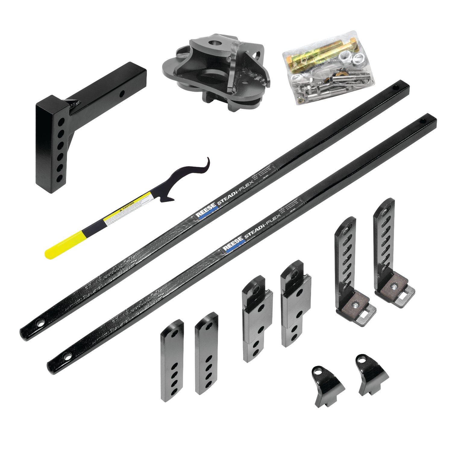
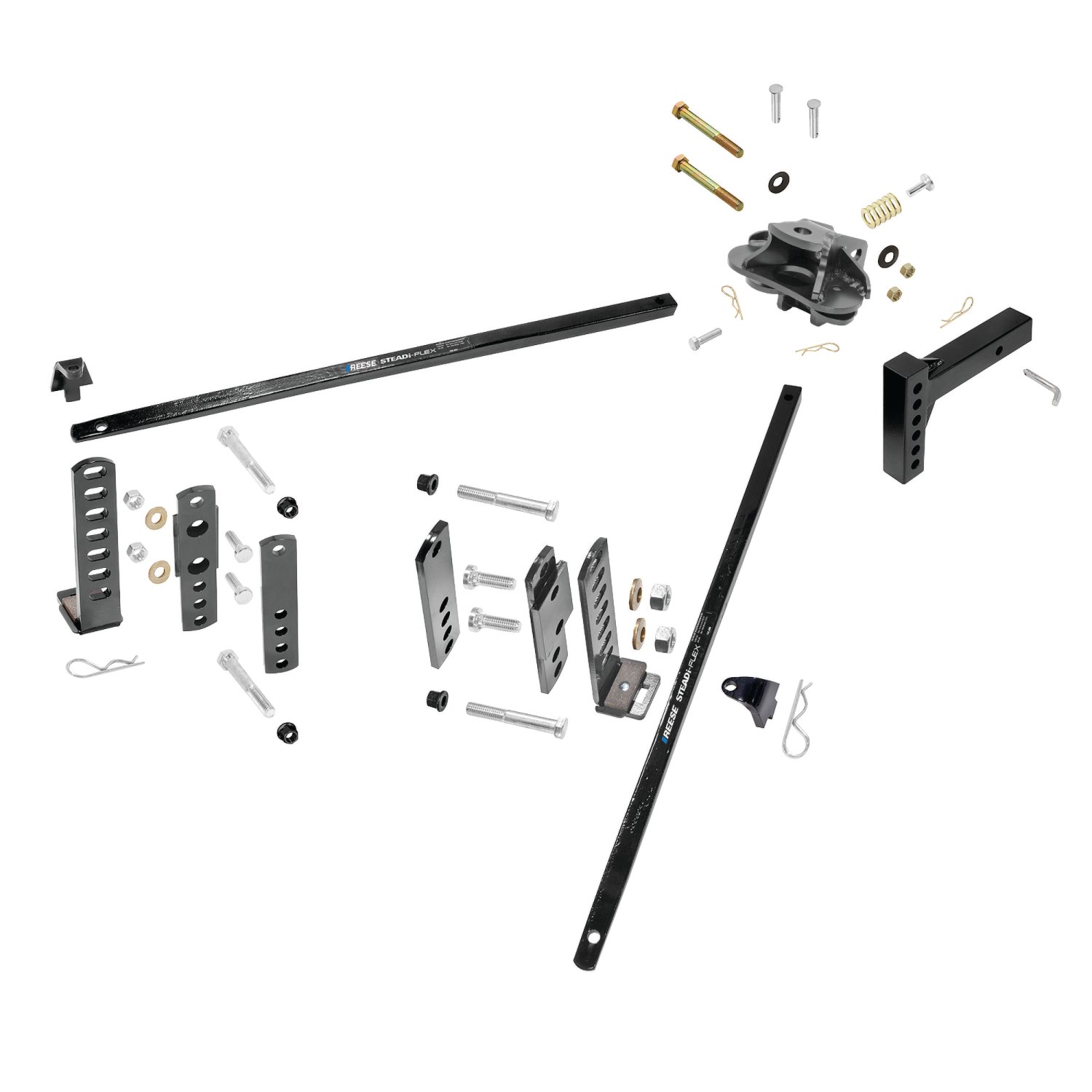
The 66557 kit includes: 1 ball mount (A), 1 draw bar (B), 2 bolts 3/4-10 x 4-1/2" GR. 8 (C), 2 conical washers 3/4" (D), 2 nuts 3/4-10 (E), 1 bolt 1/2-13 x 1-1/4" GR. 5 (F), 2 spring bar pins 1/2" x 2-1/4" (G), 2 clips (H), 1 adjustment pin (J), 6 adjustment washers (K), 2 L-brackets (L), 2 outer frame bracket assemblies (M), 2 inner straps (N), 2 friction pads (O), 4 flange lock nuts 1/2-13 (P), 4 bolts 1/2-13 x 1-1/4" (R), 4 conical washers 1/2" (S), 4 bolts 1/2-13 x 3.50" GR. 5 (T), and 2 nuts 1/2-13 (U). Additional hardware varies by frame height (see Figs. 3 and 4).
The 66558 kit includes: 1 ball mount (A), 1 draw bar (B), 2 bolts 3/4-10 x 4-1/2" GR. 8 (C), 2 conical washers 3/4" (D), 2 nuts 3/4-10 (E), 1 bolt 1/2-13 x 1-1/4" GR. 5 (F), 2 spring bar pins 1/2" x 2-1/4" (G), 2 clips (H), 1 adjustment pin (J), 6 adjustment washers (K), 2 L-brackets (L), 2 outer frame bracket assemblies (V), 2 inner straps (W), 2 friction pads (O), 4 flange lock nuts 1/2-13 (P), 4 bolts 1/2-13 x 1.25" (R), 4 conical washers 1/2" (S), and 4 bolts 1/2-13 x 3.50" GR. 5 (U).
No. The manual does not require battery disconnection. This is a mechanical hitch system with no electrical components.
Yes. The frame brackets must be bolted to the trailer's A-frame. The trailer must be positioned so the A-frame is accessible. The manual does not specify whether the trailer must be completely removed from the tow vehicle, but access to both sides of the A-frame is required.
Yes. The manual states "Make sure trailer is setting level" when measuring coupler height and during ball mount adjustment. Use the trailer's tongue jack to level the trailer before proceeding with installation.
Weigh the loaded trailer tongue using a tongue weight scale. Position the scale under the trailer coupler with the trailer fully loaded and level. The measured tongue weight must match or be below the system's rating: 250–400 lb for the 66557, or 400–600 lb for the 66558. Choose a system with a tongue weight rating at or above the actual measured tongue weight.
The system accepts either a 2" or 2-5/16" ball with a 1" shank. Check your trailer coupler to determine which size is correct. The ball is not included in the kit; you must purchase it separately and torque the nut according to the ball manufacturer's instruction sheet.
Insert the draw bar (B) into the tow vehicle receiver in your desired orientation. Install the pull pin and clip to secure it. The draw bar is the connection point between the tow vehicle and the ball mount assembly.
Measure the coupler height of your loaded, level trailer. Set the ball mount so the ball height is approximately 1" higher than the coupler height. This is the starting position. You will fine-tune this later using adjustment washers (K) after the spring bars are loaded. See Fig. 2 for the range of height adjustments available.
Install bolt (C) in the bottom hole of the ball mount and bolt (C) with washers (D) in the upper hole. Attach nut (E) to both bolts. Leave the nuts loose at this time—do not tighten them until the desired angle is achieved and the spring bars are loaded.
Use Fig. 3. Place the upper bolt (T) through the outer frame bracket (M) and inner strap (N), positioning it over the A-frame. Keep the bottom bolt (T) close to the bottom of the frame. Place the L-bracket (L) in the middle of its height adjustment. Thread bolts (R) with washers (S) into the threaded holes in the outer frame bracket (M), leaving them finger-tight. Repeat on the other side. Keep at least 3" of spring bar extending beyond the L-bracket. Torque the flange nuts (P) to 75 ft.-lbs., tightening evenly. Do not tighten one completely before the other, or the inner strap (N) will bend.
Use Fig. 4. Place the upper bolt (T) through the outer frame bracket (M) and inner strap (N) over the A-frame. Keep the bottom bolt (Q) close to the bottom of the frame. If it is not, move the top bolt (T) slightly down and toward the lower setting. Thread bolt (Q) through the outer frame bracket assembly (M). Place the L-bracket (L) in the middle of its height adjustment. Thread bolt (R) with washer (S) into the threaded hole in the outer frame bracket (M). Thread nut (U) with washer (S) over bolt (Q). Leave bolts (R) and nut (U) finger-tight. Repeat on the other side. Keep at least 3" of spring bar extending beyond the L-bracket. Torque nut (P) and bolt (Q) to 75 ft.-lbs., tightening evenly. Do not tighten one completely before the other, or the inner strap (N) will bend.
Place the upper bolt (U) through the outer frame bracket assembly (V) and inner strap (W), positioning it over the A-frame. Place another bolt (U) in the bottom hole of the bracket, keeping it as high and close to the frame as possible. Install nut (P) on both bolts. Place the L-bracket (L) in the middle of its height adjustment and secure by threading bolts (R) with washers (S) into the threaded frame bracket assembly (V), leaving them finger-tight. Repeat on the other side. Keep at least 3" of spring bar extending beyond the L-bracket. Torque the flange nuts (P) to 75 ft.-lbs., tightening evenly. Do not tighten one completely before the other, or the inner strap (W) will bend.
Finger-tight means tightened by hand only, without tools, until snug but not fully torqued. This allows the L-brackets to adjust to the spring bar angle once the spring bars are loaded. Do not use a wrench or socket to tighten these bolts initially.
With the trailer not connected, mark reference points on the front and rear wheel wells of the tow vehicle and measure the distance to the pavement. Insert the spring bars into the ball mount (A) and secure with pin (G) and clip (H), applying lubricant to the spring bars as you insert them. With the trailer coupled and level, the spring bar should be 3" below the friction pad for the 400 lb system or 4" below for the 600 lb system (Fig. 5). Add or remove adjustment washers (K) to achieve this dimension. Each washer moves the spring bars approximately 5/8" to 3/4" downward. For the 66557 with 250 lb tongue weight, 1–2 washers may be sufficient. For the 66558 with 600 lb tongue weight, 3–4 washers may be needed.
Keep the coupler attached to the ball. Raise the coupler using the tongue jack until the spring bar will fit onto the L-bracket (L). If the jack will not raise it high enough, use the lifting handle (Fig. 8): place the hooked end into the rectangular hole of the L-bracket, position the spring bar end as shown, and lift the handle. Remove the handle. Place the spring bar retention bracket (I) into the L-bracket and secure with clip (H) (Fig. 9). Always stand to the side of the lift handle; never stand at the end or allow any part of your body under the handle.
Lower the tongue jack and re-measure the front wheel well reference point. The front wheel height must be equal to the original measurement taken with the trailer disconnected. If the front wheel height is higher than originally measured, increase the head tilt angle (tilt downward). If it is substantially lower (1" or more), reduce the head tilt angle (tilt upward). For coarse adjustment, lower the L-bracket one hole. If adjustments are made, repeat the hook-up steps until the front wheel well height is approximately equal to the original measurement. It is preferred that the rear of the vehicle settle about the same amount or more than the front.
Keep bolts (R) finger-tight until the spring bars are in place and loaded with pressure on the L-brackets (L). This allows the L-brackets to adjust themselves to the spring bar angle, maximizing contact with the friction pad (O) and improving sway control. Once the spring bars are loaded and the system is adjusted correctly, tighten bolts (R) to 75 ft.-lbs. If you tightened the bolts before applying spring bar tension, loosen them slightly (do not remove completely), allow the L-bracket to self-adjust, and then re-tighten to 75 ft.-lbs.
Torque both 3/4" nuts (E) to 300 ft.-lbs. when the desired angle is achieved. If a torque wrench large enough is not available, torque the nuts to 150 ft.-lbs. and then tighten them an additional 1/4 turn. Do not lubricate the threads.
Torque the flange nuts (P) to 75 ft.-lbs. Tighten them evenly—do not tighten one completely before tightening the other. Uneven tightening will bend the inner strap (N or W).
Torque bolts (R) to 75 ft.-lbs. after the spring bars are loaded and the system is adjusted correctly. Keep them finger-tight until the spring bars are in place and loaded.
The ball mount uses two 3/4-10 x 4-1/2" Grade 8 hex head bolts (C), two 3/4" conical washers (D), and two 3/4-10 nuts (E). These bolts are torqued to 300 ft.-lbs. (or 150 ft.-lbs. plus 1/4 turn if a larger torque wrench is unavailable).
At least 3" of the spring bar must extend beyond the L-bracket (L). This is shown in Fig. 5 and is required for proper system function.
With the trailer coupled and level, the spring bar should be positioned 3" below the friction pad for the 400 lb system (66558) and 4" below the friction pad for the 600 lb system (66558). For the 66557 with 250 lb tongue weight, fewer washers may be needed. Adjust using washers (K); each washer moves the spring bars approximately 5/8" to 3/4" downward.
Frame brackets can be located within a range of 25" to 32" from the coupler ball center to the center of the friction pad (Chart 1). This range allows for positioning around obstructions such as propane bottles or batteries.
Loaded ball height must never be greater than uncoupled ball height. If the loaded ball is higher than the uncoupled ball, the front wheels of the tow vehicle will be overloaded, the rear wheels will lose traction, and the vehicle may become unstable, lose braking ability, and tend to jackknife when turning and braking simultaneously. If this occurs, re-adjust the head and re-measure until proper height is obtained.
No. Do not attempt to tow any type of trailer behind another trailer. Towing multiple trailers may cause severe instability, loss of control, and/or structural failure, resulting in vehicle accident, property damage, and personal injury. Towing multiple trailers is illegal in many jurisdictions.
No. Do not attempt to hook up or tow with rear wheels of a front-wheel-drive vehicle removed. Severe structural damage to the towing vehicle, hitch, and trailer may result. A towing vehicle/trailer combination cannot be controlled adequately unless the towing vehicle's rear wheels are carrying their share of the load.
Always stand to the side of the lift handle. Never stand at the end of the handle or allow any part of your body under the handle or spring bar. The lifting handle is used to raise the spring bar onto the L-bracket when the tongue jack cannot raise the coupler high enough.
Block the trailer wheels front and rear. Raise the tongue of the trailer with the tongue jack as high as possible, usually 8–12 inches. Always stand to the side of the lift handle; never stand at the end or allow any part of your body under the handle or spring bar.
No. Trailers should not be occupied while being towed, under any circumstances.
At the beginning of every towing day: (1) Clean the ball and coupler socket and coat the ball lightly with grease. (2) Check that all bolts are properly tightened and the hitch pin and clip are securely in place. (3) Check that electrical hookups are in working order and safety chains are connected.
Pull over and make a thorough inspection. Correct any problems before resuming travel. Severe bumps and badly undulating roads can damage the towing vehicle, hitch, and trailer, so negotiate them at a slow, steady speed.
Lubricate the hitch ball to prevent unnecessary wear. Apply lubricant to the spring bars as you insert them into the ball mount. Lubricate the surface of contact in the ball mount where the spring bars insert. Do not lubricate the friction pads. Excess oil and dirt should be wiped out whenever the trailer is uncoupled. Do not lubricate the threads of the ball mount nuts.
Keep the head assembly free of dirt and well lubricated. Excessive wear may indicate overload or inadequate lubrication. Keep the hitch painted to prevent rust and maintain a good appearance. Do not paint over labels.
Yes. Remove the hitch from the towing vehicle receiver when not towing to prevent contamination of the head sockets, reduce the chance of striking the hitch on driveway ramps or other objects, and minimize damage in the event of a rear-end collision.
Tongue weight should be about 10–15 percent of the gross trailer weight for most trailers. Too low a percentage of tongue weight will often produce a tendency to sway. Excess weight on the tongue can also lead to sway and damage the hitch and/or tow vehicle.
Unless specified otherwise by the towing vehicle or trailer manufacturer, tires should be inflated to their maximum recommended pressure.
Torque the 3/4" nuts (E) to 300 ft.-lbs., or 150 ft.-lbs. plus 1/4 turn if a larger wrench is unavailable. Do not lubricate the threads.
Torque flange nuts (P) and L-bracket bolts (R) to 75 ft.-lbs. Tighten evenly to avoid bending the inner strap.
Loaded ball height must never exceed uncoupled ball height. If it does, the front wheels will overload, rear traction will be lost, and the vehicle may jackknife. Re-adjust and re-measure until correct.
Before each towing day, clean and grease the ball, check all bolts are tight, and verify the hitch pin and clip are secure. Keep the head assembly clean and lubricated. Do not lubricate friction pads. Remove the hitch when not towing.
The head tilt angle must be increased (tilted downward). The spring bars are not applying enough downward pressure. Adjust the ball mount angle by tilting the head further down, or raise the L-bracket to a higher position. Unload and remove the spring bars before making adjustments. Repeat the hook-up steps until the front wheel height is approximately equal to the original measurement.
The head tilt angle must be reduced (tilted upward). The spring bars are applying too much downward pressure. Adjust the ball mount angle by tilting the head upward, or lower the L-bracket to a lower position. Unload and remove the spring bars before making adjustments. Repeat the hook-up steps until the front wheel height is approximately equal to the original measurement.
Use the lifting handle shown in Fig. 8. Place the hooked end of the handle in the rectangular hole of the L-bracket (L). Position the end of the spring bar as shown in the figure and lift the handle. Remove the handle. This will raise the spring bar enough to fit onto the L-bracket.
Loosen the bolts (R) slightly. Do not remove them completely—they are under pressure from the spring bars. The L-bracket (L) will then adjust to the spring bar angle by itself. Once adjusted, re-tighten the bolts (R) to 75 ft.-lbs.
The flange nuts (P) were tightened unevenly. One nut was tightened completely before the other, which bent the inner strap. The manual explicitly warns against this. To prevent further damage, always tighten the nuts evenly, alternating between sides.
This is a critical safety problem. The front wheels of the tow vehicle will be overloaded, the rear wheels will lose traction, and the vehicle may become unstable, lose braking ability, and tend to jackknife when turning and braking simultaneously. Re-adjust the head tilt angle and re-measure the ball heights until the loaded height is equal to or lower than the uncoupled height.
Sam
Ordered online. Shipment arrived on time and with all the correct parts. Great customer service and friendly staff. Also, pricing was great!
May 22, 2023
On Sale Today
Original price was $975.00. Current price is $809.68.You save $165.32 (17%)
Free Shipping
Ships free on all orders
 Authorized Dealer
Quick Ship
In stock and ready to ship — order now!
FREE ShippingFREE SHIPPING
Estimated delivery Mon, Oct 12 - Thu, Oct 15
Order before 2 PM EST Monday–Friday for same-day processing
Guaranteed safe & secure checkout